6 pole AMB as a drive of elliptic rotor – initial study supported by the virtual prototype
Abstract
This elaboration presents an initial study of the elliptic rotor driven by the active magnetic bearing consisting of 6 poles. The analysis was realized using the virtual prototype - a numerical model of device. The model was realized with support of COMSOL Multiphysics software. The proposed geometry, selected materials and configuration were used to perform analysis if the electromagnetic forces and torque are available to drive the rotor of the elliptic shape. The control study is given to obtain a rotational motion for a fixed rotor placement at the bearing center. Numerical simulations were realized to demonstrate features and limitations of the proposed solution. The solution in a form of Virtual Prototype allows to eliminate prototyping costs and extends the knowledge and dependencies of complex mechatronic systems like active magnetic levitation technology based ones.
1.Concept
The primary task of active magnetic levitation device is to keep the object in the levitation mode [3,15,20]. Typically, the rotational motion is forced by the external or built in rotor drive. The Active Magnetic Bearing (AMB) has a feature to drive the levitating object. The AMB can be combined with reluctance or permanent magnets type rotors to operate as a self-bearing drive. Additional feature of the levitation device is the motion of the levitation object. It is well known, that the positioning stages, self-bearing drives and maglev trains are design in a such way. Most of them uses permanent magnets to achieve required forces and torque. One can find a number of different solutions for combined bearings and motors resulting in bearingless drives [1,3–13,21].
The concept of this research is not new. In order to achieve rotational motion of the rotor regardless of the levitation of the rotor, it is necessary to make the rotor in the bearing space with an elliptical cross-section and introduce the appropriate control. The study of an elliptic shape rotor in typical 8 pole heteropolar AMB was considered in [4] (Fig. 1) on the basis of study given by [22].
![Control concept of elliptic rotor [4].](https://ip.ios.semcs.net:443/media/jae/2020/63-1/jae-63-1-jae209006/jae-63-jae209006-g001.jpg)
This solution can be applied when the drive torque is sufficient to keep the rotational speed of the rotor (e.g. in gyroscopes). This solution can find an application in micromechanics [2,10]. Proper control of magnetic bearing windings should ensure levitation and rotation of the rotor. It is easy to see that electromagnetic forces will play a role in both driving and braking. Therefore, the development of the configuration of such a system requires detailed analysis, simulation and experimental testing.
Author of this research was inspired by Prof. Z. Gosiewski to do some research in this field. The virtual prototype of the 8 poles AMB with elliptic rotor was realized [14]. In this elaboration the problem is considered once again with the AMB with 6 poles due to conclusion related to ellipse detection. The new and original is the proposal of AMB with 6 poles is the minimal configuration that allows to detect the location and orientation of the elliptic rotor in a direct or indirect way using direct measurements by displacement sensors, flux sensors located in poles or by the estimation computed on the basis of electrical quantities being measured. The AMB can be constructed with internal or external poles. The key point is that shape of the ellipse can be unambiguously determined by knowing the six points contained in its contour.
The considered configuration can be qualified as a reluctance motor. It must be stated that for the levitation purposes the electromagnetic forces acting in the bearing plane must be able to keep the rotor in levitation mode by the lateral stiffness and damping control [19]. Therefore, the problem is interesting from the interdisciplinary point of view and application field – the construction must be well fitted to realizable control task and application. This elaboration will is an initial research in this field.
2.Elliptic shape rotor and gap
A characteristic feature of the discussed solution is the rotor, whose outer contour is an ellipse. For the research purposes the rotor was designed in a form of ring with internal circular hole. The ring can be fitted to the solid or pipe-type rotors or filled in with different components (e.g. impeller) in the case of self-bearing drive applications.
The ferromagnetic steel was chosen as a material for the rotor. From the mechanical point of view the thickness of the ring (especially in regions around the minor axis) should be considered due the material strength. On the other hand, one can remind that the rotor is a part of magnetic flux path, so the magnetization properties ought to be considered as well.
The contour of the rotor with an elliptical cross-section with the center at the point (x0, y0) and the 2ae – major and 2be minor axes of the ellipse describes the equation:
(1)
Fig. 2.
An elliptical impeller positioned adjacent to the C-shaped electromagnet in the center of the bearing for different angles of rotation: (a) 𝛩 = 0; (b) 𝛩 = 𝜋∕2 [15].
![An elliptical impeller positioned adjacent to the C-shaped electromagnet in the center of the bearing for different angles of rotation: (a) 𝛩 = 0; (b) 𝛩 = 𝜋∕2 [15].](https://ip.ios.semcs.net:443/media/jae/2020/63-1/jae-63-1-jae209006/jae-63-jae209006-g002.jpg)
Fig. 3.
An elliptical impeller placed in the bearing space adjacent to the pole piece at the point (xe0, ye0) and rotated by an angle 𝛩 relative to the horizontal axis of the bearing [15].
![An elliptical impeller placed in the bearing space adjacent to the pole piece at the point (xe0, ye0) and rotated by an angle 𝛩 relative to the horizontal axis of the bearing [15].](https://ip.ios.semcs.net:443/media/jae/2020/63-1/jae-63-1-jae209006/jae-63-jae209006-g003.jpg)
Assuming that the rotor is parallel to the bearing poles (not skewed), the gap volume problem is reduced to determining the surface area of the Si and further multiplication with rotor/bearing height. According to the Fig. 3, the surface area Si can be determined on the basis of the Green theorem due to the k-contour closed by the curvature of the pole k2 constituting the circle of radius R, virtual extensions with the linear functions of the pole piece in the form of segments k1 and k3 and arc of the rotor k4 defined by the points of its intersection with straight lines pole pieces:
(2)
(3)
(4)
(5)
(6)
(7)
3.Experimental and numerical force investigation
An experimental investigation [15] of the electromagnetic force Fem acting on the elliptic rotor (load Fw) was done (see Fig. 4). The force characteristics for the rotor aligned to the axis of C shape electromagnet with minor and major axis is presented in Figs 4b and 4c respectively. For the same electromagnet shape a numerical model has been realized in COMSOL Multiphysics. The depth of the model was set to 10 mm. The Electromagnet radius is Rem = 25.9 mm, the elliptic rotor is characterized by major and minor radius Ra = Rem − k ⋅ d, and Rb = Rem − (k +1) ⋅ d to perform parametric investigation of the electromagnetic force for a few configurations of the elliptic shape. The numerical analysis were realized with d = 100 μm, k = 1..5, and coil current i = 1..3 A. The coil is characterized by number of turns equal to 100, and coil diameter equal to 0.3 mm. The electromagnetic force values were computed for two orientations (minor axis aligned horizontally, and vertically) of the elliptic rotor and presented in Fig. 5a and 5b respectively.
Fig. 4.
Electromagnetic force test in the presence of an elliptical rotor: (a) test stand with one actuator; (b) force with horizontal orientation of the rotor; (c) force with vertical orientation of the rotor [15].
![Electromagnetic force test in the presence of an elliptical rotor: (a) test stand with one actuator; (b) force with horizontal orientation of the rotor; (c) force with vertical orientation of the rotor [15].](https://ip.ios.semcs.net:443/media/jae/2020/63-1/jae-63-1-jae209006/jae-63-jae209006-g004.jpg)
Fig. 5.
Electromagnetic force as a solution of numerical model for variable rotor geometry defined by k constant: (a) force with horizontal orientation of the rotor; (b) force with vertical orientation of the rotor.
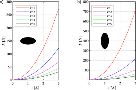
One can find that the electromagnetic force vary with respect to the elliptic shape. When the gap decreases the force value increases. Therefore the seek for appropriate rotor-stator configuration is requested.
4.Virtual prototype
The 2D model of the conceptual device was developed in COMSOL Multiphysics software. Soft iron, cooper and air materials were applied to stator and rotor, coils and free space respectively. The numerical models were prepared for stationary and time dependent analysis. The 10 mm thick ellipse with major axis equal to 50 mm and minor in range of 48.0 ÷ 49.9 mm was located in the AMB with air gap adjusted in a range of 100 ÷ 500 μm. The Virtual Prototype was configured with parameters summarized in Table 1. The configuration of the rotor-baring system is depicted in Fig. 6.
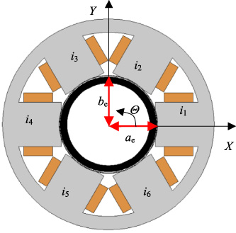
Fig. 6.
Configuration of the 6 pole AMB and elliptic rotor.
To solve the problem numerically, the regions were discretized to achieve a good quality of the mesh. Mesh was designed in a custom way and optimized to achieve proper calculations of the torque calculations - sensitive to model discretization.
Computations were realized with support of super computer called Prometheus installed at Cyfronet AGH. The problem was solved using 24 Intel Xenon processors and 120 GB of RAM. The developed virtual prototype allows to perform many variants of studies. The following questions were specified:
what is the influence of rotor geometry for values of forces and torque?
what is influence the levitation gap for values of forces and torque?
what are the consequences of the different coils supply for the values of force and torque?
is it possible to set control sequence to achieve rotor rotations?
The simulation results are summarized in chapters 5 ÷ 7, plotted and summarized in tables to visualize differences between variants and consequences of parameters variations. Please have a look at nonlinearities existing in the considered solution.
Table 1
Summary of parameters
| Parameter | Value | |
| Rbe | Outer stator radius | 55 mm |
| Rbi | Inner stator radius | 48 mm |
| Rp | Pole radius | 25.05 mm |
| 2ae | Major axis of the ellipse | 50 mm |
| 2be | Minor axis of the ellipse | 49.5 mm |
| Rc | Internal rotor cylinder diameter | 43 mm |
| he | Rotor and stator height | 10 mm |
| dc | Coil wire diameter | 0.7 mm |
| w | Pole width | 23 mm |
| N | No of turns | 83 |
| ino | Nominal coil current | 1 A |
| m | Rotor mass | 38.595 g |
| JX | Moment of inertia | 1.1122 ⋅ 10−8 kg ⋅ m2 |
| JY | Moment of inertia | 1.3027 ⋅ 10−8 kg ⋅ m2 |
| JZZ | Moment of inertia | 2.3975 ⋅ 10−8 kg ⋅ m2 |
5.Investigation of torque and forces vs ellipse dimmension
The ellipse minor axis was chosen to investigate the dependencies on electromagnetic torque and forces. The calculations were realized for a C shape electromagnet combined using coils 1 and 2 only, steering them with i1 = inom and i2 = −inom respectively. Distribution of the magnetic flux density is presented in Fig. 7. Figures 8 ÷ 12 presents X and Y components of the electromagnetic force and axial torque calculated stationary for the arbitrary set rotor orientation via 𝛩 angle. The obtained results were analyzed and summarized in Table 2. One can find the torque ripple appears and increases with the enlargement of the air gap caused by the decrease of the minor ellipse axis. This effect comes from the variable reluctance of the air gap while the ellipse rotates in the front of poles. The Tax zero crossing indicates rotation angle and well correlates with the minor and major axis orientation with respect to the AMB pole.
Fig. 7.
Magnetic flux density distribution for the rotor 2ae = 50.0 mm, 2be = 49.9 mm and coil curent of 1A applied to coils 1 and 2.
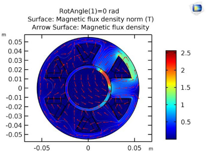
Fig. 8.
Force and torque values calculated at gap 100 μm for an ellipse 2ae = 50.0 mm, 2be = 49.9 mm.
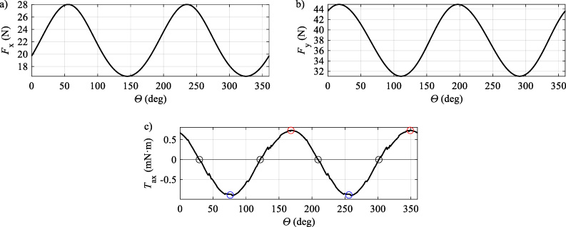
Fig. 9.
Force and torque values calculated at gap 100 μm for an ellipse 2ae = 50.0 mm, 2be = 49.5 mm.

Fig. 10.
Force and torque values calculated at gap 100 μm for an ellipse 2ae = 50.0 mm, 2be = 49.0 mm.
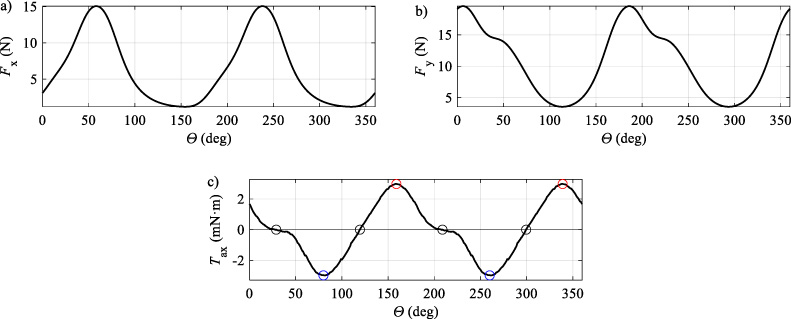
Fig. 11.
Force and torque values calculated at gap 100 μm for an ellipse 2ae = 50.0 mm, 2be = 48.5 mm.
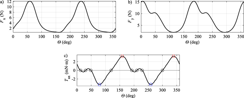
Fig. 12.
Force and torque values calculated at gap 100 μm for an ellipse 2ae = 50.0 mm, 2be = 48.0 mm.
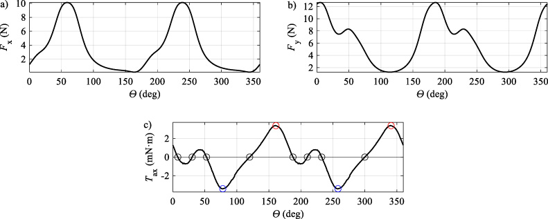
Table 2
Results of Simulations corresponding to Ellipse size
| be | 𝛩 [deg] if Tax = 0 | Tax Min/Max [mN ⋅ m] (𝛩 [deg]) | Fx Min/Max [N] | Fy Min/Max [N] |
| 49.9 | 29.17 | −0.8848 | 16.43 | 31.03 |
| 121.39 | (76.256) | |||
| 209.17 | 0.73 | 28.02 | 44.91 | |
| 301.39 | (168, 349) | |||
| 49.5 | 28.3 | --2.47 | 3.62 | 8.61 |
| 119.8 | (80.260) | |||
| 208.3 | 2.41 | 20.11 | 27.82 | |
| 299.8 | (160, 340) | |||
| 49.0 | 28.14 | −2.97 | 1.19 | 3.55 |
| 119.30 | (80.260) | |||
| 208.14 | 2.97 | 15.06 | 19.57 | |
| 299.30 | (159.339) | |||
| 48.5 | 12.64 | −3.26 | 0.47 | 1.97 |
| 30.12 | (79.259) | |||
| 48.65 | 3.25 | 12.10 | 15.32 | |
| 120.04 | (159.339) | |||
| 192.64 | ||||
| 210.12 | ||||
| 228.65 | ||||
| 300.04 | ||||
| 48.0 | 7.68 | −3.40 | 0.13 | 1.27 |
| 30.11 | (78.258) | |||
| 52.54 | 10.13 | 12.65 | ||
| 119.99 | 3.37 | |||
| 187.68 | (161.341) | |||
| 210.11 | ||||
| 232.54 | ||||
| 299.99 |
As the minor axis of the ellipse decreases, the torque value increases and the values of the electromagnetic force components decrease. Too large change in the minor axis of the ellipse causes the appearance of ripples at the torque. This study confirmed that the selection of the shape of an ellipse is an important issue, especially in the case of a self-bearing drive configuration, in which it will be required to enable appropriate radial forces to maintain the rotor in the levitation mode. Therefore, a compromise will be necessary with the final selection of the rotor shape depending on the target configuration of the rotor with the equipment.
6.Investigation of torque and forces vs levitation gap
Next, the influence of the levitation gap on the values of the electromagnetic force components and the torque at the invariant rotor configuration was investigated. Again, the 1 and 2 coils were electrified only, as in chapter 5. This was achieved by reducing the height of the pole pieces. Due to the relatively long magnetic flux path (about 100 mm) the error in the comparison of results will be negligible. The calculation results are presented in Figs. 13, 14, 15, 16, 17 and summarized in the Table 3.
Table 3
Results of simulations corresponding to variable gap
| Gap [μm] | 𝛩 [deg] if Tax = 0 | Tax Min/Max [mN ⋅ m] (𝛩 [deg]) | Fx Min/Max [N] | Fy Min/Max [N] |
| 100 | 28.25 | −2.47 | 3.62 | 8.61 |
| 119.80 | (80.260) | |||
| 208.25 | 2.41 | 20.11 | 27.83 | |
| 299.80 | (160, 340) | |||
| 200 | 30.44 | −1.30 | 2.54 | 5.32 |
| 118.52 | (81.261) | |||
| 210.44 | 1.25 | 7.81 | 11.53 | |
| 298.53 | (156, 336) | |||
| 300 | 34.70 | −0.78 | 1.85 | 3.68 |
| 119.71 | (77.257) | |||
| 214.70 | 0.86 | 4.31 | 6.60 | |
| 299.71 | (161, 341) | |||
| 400 | 29.38 | −0.56 | 1.41 | 2.73 |
| 120.19 | (79.259) | 2.78 | 4.37 | |
| 209.38 | 0.57 | |||
| 300.19 | (162,342) | |||
| 500 | 29.65 | −0.42 | 1.12 | 2.12 |
| 120.06 | (79.259) | 1.97 | 3.15 | |
| 209.66 | 0.4178 | |||
| 300.12 | (162, 342) |
The results of simulation tests confirmed the expectations that with the increase of the gap for the determined configuration of the elliptical rotor the torque and electromagnetic forces will be reduced. Subtle fluctuations in zero places are rather related to the numerical method, discretization of the levitation area.
7.Investigation of torque and forces for coils supply scenarios
The next study consisted in examining the influence of push-pull control on pole pieces on the value of torque and forces. The rotor and bearing configuration with the basic parameters listed in Table 1 were tested. Originally, only coils 1 and 4 were steered. The obtained moment turned out to be significantly smaller than the results obtained when controlling neighboring windings. Therefore, in subsequent tests, three control configurations were established to supply two pairs of windings. The results of the calculations are shown in Fig. 18, and their detailed analysis is presented in Table 4. Comparing the results from Fig. 13, it can be seen that the torque values doubled due to the use of a differential configuration in the winding control. Moreover, the electromagnetic force components compensate one to each other thanks to the opposite action. In this case a key point in the future research will be to keep the rotor in levitation close to the bearing center.
Fig. 13.
Force and torque values calculated for an ellipse 2ae = 50.0 mm, 2be = 49.5 mm at 100 μm gap.

Fig. 14.
Force and torque values calculated for an ellipse 2ae = 50.0 mm, 2be = 49.5 mm at 200 μm gap.
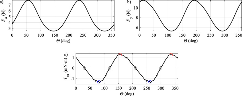
Fig. 15.
Force and torque values calculated for an ellipse 2ae = 50.0 mm, 2be = 49.5 mm at 300 μm gap.
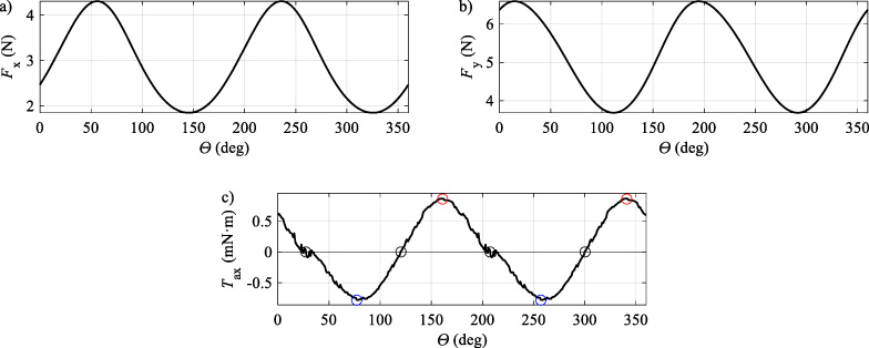
Fig. 16.
Force and torque values calculated for an ellipse 2ae = 50.0 mm, 2be = 49.5 mm at 400 μm gap.
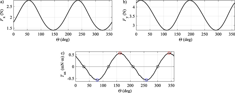
Fig. 17.
Force and torque values calculated for an ellipse 2ae = 50.0 mm, 2be = 49.5 mm at 500 μm gap.
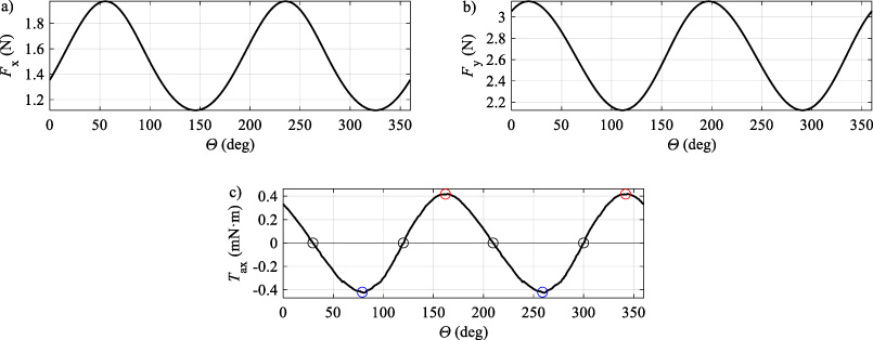
Fig. 18.
Torque calculated for elliptic rotor (2ae = 50 mm, 2be = 49.5 mm) at bearing gap equal to 100 μm, under control of coils: (a) 1 and 4, (b) 1–2 and 4–5, (c) 2–3 and 5–6, (d) 3–4 and 6–1.
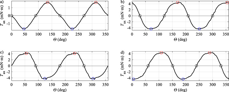
Table 4
Summary of control scenarios
| Coils | 𝛩 [deg] if Tax = 0 | Tax Min/Max [mN ⋅ m] (𝛩 [deg]) | Fx Min/Max [mN] | Fy Min/Max [mN] |
| 1–4 | 0.13 | −1.67 | −1.21 | −0.50 |
| 90.37 | (46.226) | 1.29 | 0.56 | |
| 180.30 | 1.670 | |||
| 270.37 | (134, 314) | |||
| 1–2 | 29.11 | −4.33 | −3.15 | −4.05 |
| 4–5 | 119.76 | (69.249) | 3.61 | 2.98 |
| 209.11 | 4.40 | |||
| 299.76 | (0, 174) | |||
| 2–3 | −0.31 | −4.22 | −2.13 | −6.44 |
| 5–6 | 90.06 | (124.304) | 2.17 | 3.53 |
| 179.92 | 4.15 | |||
| 270.06 | (55, 235) | |||
| 3–4 | 59.86 | −4.38 | −2.64 | −3.66 |
| 6–1 | 151.01 | (5.190) | 3.82 | 3.21 |
| 239.86 | 4.29 | |||
| 331.01 | (109, 289) |
The magnetic field distribution the elliptic rotor oriented at 𝛩 = 60° and 𝛩 = 150° under the control of coils 3–4 and 6–1 is presented in Fig. 19.
Fig. 19.
Illustration of magnetic field distribution for elliptic rotor rotated at 60 and 150 degrees with activated coils 3, 4, 6, and 1.
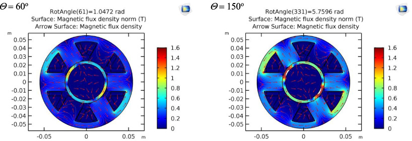
Fig. 20.
Proposed control sequences to achieve rotational motion.
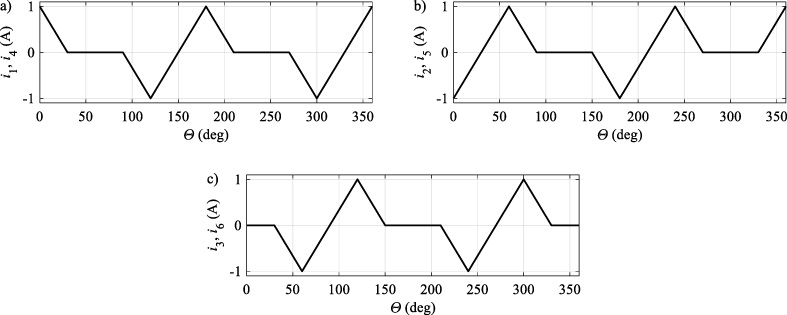
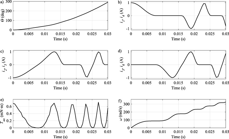
Fig. 21.
Rotation of the rotor (a) realized by the control sequence determined by coil currents (b ÷ d) in an open loop. The pulsating torque (e) generates an rotation with increasing speed (f).
8.Control sequence for rotation task
Next, the model was reconfigured to solve the magnetic field problem in time domain with a 500 μs maximal step size. Additionally, the ordinary differential equation of rotational motion (8) was embedded into the model.
(8)
As a result of the calculations, rotor rotation was obtained. It should be noted that the motion Eq. (8) does not take into account external loads, friction, and that the control system guarantees the desired current in the bearing’s windings. More, the control takes place in an open control system without the participation of the regulator stabilizing the levitation of the rotor in the bearing space. The control signals (see Fig. 20) after embedding into the model have been converted using cubic interpolation to guarantee the continuity and differentiability of the control signal. A such signal smoothing is requested to guarantee the stability of the numerical method. Analysis of control signals shows that the system is working properly, and the variable torque is a consequence of a such control sequence of windings currents. Due to the started rotor rotation the control sequence vary with time due to the passed rotation angle 𝛩. The rotational motion equation is solved on the basis of the Tax value obtained from magnetic field calculations. Due to the stator-rotor configuration and proposed control i1..6 (𝛩) scheme the torque is pulsating and therefore the variable speed is obtained. Nevertheless, the rotor is accelerated. According to the Eq. (8) the rotation angle is obtained by the integration of rotational velocity. A complete simulation result of the rotor start-up is presented in Fig. 21. Even the velocity remain constant in some periods the rotor rotates due to the neglected rotational friction in the Eq. (8). Further research should take into account the extension of the model in order to obtain levitation and the implementation of both regulators for position and rotation. The resultant control will be a synergy of both controls and it should be non-linear considering the position and angle of rotation of the rotor. The study of a simulation model with an elliptical rotor also showed how important it is to examine the forces and torques affecting the cylindrical rotor as it occurs in typical magnetic bearings based rotor machines, in the case of the rotor moving across the bearing space [15] and in the case of the device, which the rotor adopts the characteristics of a flexible rotor. Modern tools and methods for designing, modeling and simulating the numerical model of the device, including the technology of magnetic levitation, allow to conduct studies on large-scale solutions [15,18].
9.Discussion on control methods and hardware
On the basis of the conducted tests, it is stated that the elliptical rotor can be subjected to a control that guarantees its levitation and rotation. For the rotor levitation the synergy of levitation forces and driving torque must be taken into account and properly designed. From the control point of view, it is required to clearly determine the position and orientation of the rotor. Thus, the use of measuring and control equipment that ensures simultaneous measurement and control application to all bearing windings becomes crucial. Therefore, it is planned to manufacture a prototype and configure the PAC (Programmable Automation Controller) [15] to perform the control task. Parallel measurement of signals from sensor systems and power system will be critical from the point of view of dynamics of motion of the rotor and the control system. Looking at the distribution of electromagnetic forces, an interesting from the point of view of the control, will be the issue of rotor start-up – introduction of levitation phase. Hypothetically, a non-linear regulator [17] will be a good solution for achieving this goal.
10.Conclusions
Summing up the presented project, the numerical model and the results of simulation research, it should be stated that the solution is functional and can find applications. The fact is that the small torque makes it impossible to compete with rotors equipped with permanent magnets. Nevertheless, the design simplicity of this solution can lead to practical applications. From a control point of view, the problem requires further in-depth analysis. Based on the numerical model developed, it will be possible to obtain a mathematical model in the form of nonlinear ordinary equations that oppose the dynamics of the rotor. Thus, it will be possible to perform stability analysis and determine the appropriate regulator. The prototype manufacturing of the considered rotor-bearing configuration is in progress. Further research will focus on optimal configuration with respect to the specified criteria, design of complete dynamical model with rotor motion and rotation in the bearing plane, levitation control, identification of Virtual Prototype to achieve ordinary differential equations, analysis of stability, controllability, observability, controller synthesis, verification in Virtual Prototype, manufacturing and experimental investigation, model verification and studies of a control strategies for the elliptic rotor based drive system.
Acknowledgements
Numerical model was proceeded by using AGH Cyfronet computational resources as a part of ActRotCtrl grant. Part of this research was realized at AGH and publication was sponsored by “Incubator of Innovation +”: project co-financed by the Ministry of Science and Higher Education under the program “Support for management of scientific research and commercialization of BR results in scientific units and enterprises” under the Intelligent Development Operational Program 2014–2020.
References
[1] | W. Amrhein and S. Silber, Bearingless single-phase motor with concentrated full pitch windings in interior rotor design, in: 6th International Symposium on Magnetic Bearings, August 5–7 1998, Massachusetts, USA, (1998) . |
[2] | H. Bleuler, H. Kawakatsu, W. Tang, W. Hseih, D. Miu, Y. Tai, F. Moesner and M. Rohner, Micromachined active magnetic bearings, in: 4th International Symposium on Magnetic Bearings, Zurich, Switzerland, August, (1994) . |
[3] | A. Chiba, T. Fukao, O. Ichikava, M. Oshima, M. Takemoto and D. Dorrel, Magnetic Bearings and Bearingless Drives, Newnes, (2005) . |
[4] | Z. Gosiewski, Magnetic Bearings for rotating Machinery – Control and Investigation (in Polish: Łożyska magnetyczne do maszyn wirnikowych, Sterowanie i badanie), Biblioteka Naukowa Instytutu Lotnictwa, Warszawa, (1999) . |
[5] | H. Grabner, W. Amrhein, S. Silber and W. Gruber, Nonlinear feedback control of a bearingless brushless DC motor, IEEE/ASME Transactions on Mechatronics 15: ((2010) ), 40–47. |
[6] | W. Gruber, W. Briewasser, M. Rothböck, R. Schöb and W. Amrhein, Bearingless reluctance slice motors, in: 13th International Symposium on Magnetic Bearings (ISMB13), Virginia, USA, August 6–9, (2012) . |
[7] | W. Gruber, W. Bauer and K. Radman, Comparison of homopolar and heteropolar bearingless reluctance slice motor prototypes, ISMB14, in: 14th International Symposium on Magnetic Bearings, Linz, Austria, August 11–14, (2014) . |
[8] | W. Gruber and S. Silber, 20 years bearingless slice motor – its developments and applications, in: The 15th International Symposium on Magnetic Bearings (ISMB15), August 3–6, 2016, Mojiko Hotel, Kitakyushu, Japan, (2016) . |
[9] | A. Maninen, V. Mukherjee, J. Pippuri and K. Tammi, A self-bearing 8/6 switched reluctance motor, in: The 15th International Symposium on Magnetic Bearings (ISMB15), 2016, Mojiko Hotel, Kitakyushu, Japan, (2016) . |
[10] | R. Mueller, H. Bleuler, U. Schlaepfer and M. Meer, Active micro motor bearing, in: 5th International Symposium on Magnetic Bearings, Kanazawa, Japan, August, (1996) . |
[11] | V. Mukherjee, A. Manninen, J. Pippuri and A. Belahcen, Analysis of electromagnetic force ripple on the rotor of a bearingless synchronous reluctance motor, in: The 15th International Symposium on Magnetic Bearings, August 3–6, 2016, Mojiko Hotel, Kitakyushu, Japan, (2016) . |
[12] | K. Nenninger, W. Amrhein and S. Silber, Bearingless single-phase motor with fractional pitch windings, in: Seventh International Symp. on Magnetic Bearings, August 23–25, 2000, ETH Zurich, (2000) . |
[13] | D.Q. Nguyen and S. Ueno, Sensorless speed control of a permanent magnet type axial gap selfbearing motor, ISMB 11, 11th International Symposium on Magnetic Bearings, August 26–29, Nara, Japan. |
[14] | A. Piłat and Z. Gosiewski, Active magnetic bearing as a drive of elliptic rotor – initial study supported by a virtual prototype, in: 10th International Conference on Mechatronic Systems and Materials (MSM 2014), 7–10 July 2014, Opole, Poland, (2014) . |
[15] | A. Piłat, Active Magnetic Levitation Systems, AGH University of Science and Technology Press, (2013) , ISSN 0867-6631. |
[16] | A. Piłat, Active Magnetic Bearing and Control System for Active Magnetic Bearing, AGH University of Science and Technology, PCT/PL2010/000123, 2010-12-10. |
[17] | A. Piłat, Feedback linearization control of AMB system, in: 8th International Symposium on Magnetic Bearing, August 26–28, 2002, Mito, Japan, (2002) . |
[18] | A. Piłat, Active magnetic suspension and bearing, in: Modelling and Simulation, InTech Education and Publishing, Vienna, (2008) , pp. 453–470. ISBN 978-3-902613-25-7. |
[19] | A. Piłat, B. Sikora and J. Źrebiec, Investigation of lateral stiffness and damping in levitation system with opposite electromagnets, in: 12th Asian Control Conference (ASCC) Kitakyushushi, Japan, June 9–12, 2019, IEEE, (2019) , e-ISBN: 978-4-88898-300-6, s. 1210–1215. |
[20] | G. Schweitzer, E.H. Maslen, H. Bleuler, M. Cole, P. Keogh, R. Larsonneur, R. Nordmann, Y. Okada and A. Traxler, Magnetic Bearings: Theory, Design, and Application to Rotating Machinery, Springer, (2009) . |
[21] | A. Silber, W. Amrhein, P. Bösch, R. Schöb and N. Barletta, Design aspects of bearingless slice motors, in: Ninth International Symposium on Magnetic Bearings, August 3–6, Lexington, Kentucky, USA, (2004) . |
[22] | V. Voronkov and G. Denisov, The effect of body’s autorotation in active magnetic bearings, in: 4th International Symposium on Magnetic Bearings, Zurich, Switzerland, (1994) . |