Influence of lateral impact on reinforced concrete piers under drying-wetting cycle and chloride ion corrosion environment
Abstract
In order to study the influence of lateral impact on reinforced concrete piers in marine environment, drop hammer impact tests were carried out on piers with different corrosion rates obtained from drying-wetting cycle and chloride ion corrosion experiment to study the crack propagation process and failure modes of piers. Then by numerical simulation, the influences of impact velocity, impact mass, compressive strength of concrete and impact number on the performance of corroded piers were studied. The results showed that the failure modes of piers with different corrosion rates under lateral impact were different. The non-corrosive and low corrosion rate piers were destroyed by the bending shear which was jointly controlled by the transverse bending crack and oblique shear crack. The medium corrosion rate pier was the bending shear failure caused by oblique shear crack. The high corrosion rate pier was the joint action of bending shear crack and rust expansion crack. The increase of impact velocity, impact mass and impact number will increase the maximum deflection and the damage of the corroded piers, but the increase degrees were different. The increase was largest when the impact number was increased. Increasing impact number from 1 to 5, the maximum deflection increased by 26.3 times and the number of damage element increased by 4.3 times. Increasing the compressive strength of concrete will decrease the damage of pier, but with less degree. Increasing the compressive strength from 25 to 45 MPa, the maximum deflection and number of damage element were decreased by 10.7% and 9.4% respectively.
1Introduction
Reinforced concrete structures in the coastal and offshore areas are eroded by chloride ions in marine environment for a long time, which leads to corrosion of the internal steel bars, early damage of the structures, and loss of durability. It has become an important hazard in the current hydraulic engineering. Many scholars have studied the properties of corroded reinforced concrete structures. Through tests and analysis, Yokota et al. [1] obtained that the variation in corrosion properties of reinforcement embedded in concrete affected the load-carrying capacity of the reinforced concrete slabs. Guo et al. [2] investigated the cyclic performance of reinforced concrete piers with chloride ion corrosion and found that the seismic performance of the structure degraded obviously with the increase of corrosion level. Based on the two-dimensional elastoplastic finite element formulation, Gao et al. [3] investigated the load-carrying capacity degradation of reinforced concrete piers wrapped with steel plates due to occurrence of corrosion at the pier base and found the load-carrying capacity of the piers decreased with the increase in corrosion rate of steel plates. Kashani et al.[4] presented a numerical model which can be used to explore the influence of corrosion on the inelastic response of corroded reinforced concrete columns.
In addition, the corrosion degree of reinforced concrete members varies with the location in the water. The part in the water level change zone and splash zone is eroded by alternating drying-wetting, which leads to the increase of the intrusion degree of chloride ions and has further adverse effects on their durability [5, 6]. Therefore, many experts have studied the effect of drying-wetting cycle accelerated corrosion on the structures. By local accelerated drying-wetting cycle and chloride ion corrosion test, Erdogdu et al. [7] studied the corrosion failure mechanism of steel bar in concrete slab. By monitoring the corrosion evolution of steel bar in reinforced concrete structure under drying-wetting alternated accelerated corrosion test, Wei et al. [8] discussed the corrosion mechanisms of corrosion evolution stages and proposed the corrosion reactions according to the corrosion product and corrosion evolution characteristics. Based on the test of different salts (bicarbonate, sulfate, and chloride salt) soak and drying-wetting cycle to structure, Su and Guo [9] obtained that under the condition of drying-wetting cycle, a variety of salts can make the erosion damage of structure produce superposition effect and make the corrosion damage aggravated. Based on accelerated drying-wetting cycle and chloride ion corrosion experiment, Artigas et al. [10] presented a methodology that could be used to predict the corrosion thickness of steels exposed for years to a specific marine environment. By extensively sampling the piers of an old bridge located close to the Pacific Ocean, Melchers et al. [11] found that corrosion loss varied with elevation relative to mean water level and was negligible in the atmospheric zone, about 2-3 mm in the immersion zone and 5-6 mm in the splash and lower tidal zones. Guo et al. [12] investigated the strength loss of coastal bridges, especially focusing on the effects of non-uniform corrosion along the height of bridge piers and found the strength loss in the splash and tidal zone was more significant than in the atmospheric zone.
With the rapid development of coastal and cross-sea bridge construction, the frequency of serious ship-bridge collision shows a clear upward trend, and the problem of ship-bridge collision has been paid more and more attention. Taking the collision process of a million tons bulk carrier with the pier as an example, Wang and Chen [13] simulated the design load and damage state of collision force of the ship, and obtained the time-history curve of the collision force and the damage form of the pier. A collision between a 2600 DWT oil tanker and the substructure of bridge was simulated using ANSYS/Ls-Dyna in Tian and Zhu [14], and analyzed energy dissipation in every part, deformation response and stress distribution of the substructure. Based on model test and dynamic simulation, Zeng [15] obtained the dynamic response of pier when it was hit by horizontal impact and established a simplified formula for calculating the collision force. Based on theory of ship-bridge collision, Liu et al. [16] established the calculation model of the bridge by ANSYS and analyzed the change of bridge energy, the stress and displacement of main parts of the bridge. Based on the numerical simulation for progressive collapse of continuous girder bridge subjected to ship impact, Tian and Huang [17] obtained the instability and excessive deformation of superstructure are the main reasons leading to the progressive collapse of the continuous girder bridge. Through refined numerical simulations of ship-rigid wall collisions under different impact velocities, Wang et al. [18] obtained impact force time-histories and proposed the impact factor method to estimate the response of piers and discussed the precision of impact factor method. Based on the scaled model tests of ship-pier collision and finite element simulations, Wan et al. [19] analyzed the damage process and failure mode of the pier.
In summary, the existing researches were mainly to study the dynamic response of the intact bridge pier to the impact load. When the ship impacts on the pier, the impact position on the pier is also the drying-wetting cycle and chloride ion corrosion zone affected by the water level, and this zone is also the most corroded zone of the whole pier. At present, the research on the impact resistance of reinforced concrete members in drying-wetting cycle and corrosion environment is seldom involved. Therefore, it is urgent to study the performance of reinforced concrete piers under the lateral impact in the environment of drying-wetting cycle and chloride ion corrosion.
In this paper, the drying-wetting cycle and chloride ion corrosion of the piers were firstly carried out to obtain the specimens with different corrosion rates. On this basis, the drop hammer impact test was carried out on the specimens to study the crack propagation process and failure mode of the corroded pier under lateral impact load. Then by using ANSYS/Ls-Dyna, the influence of various factors on the performance of corroded piers were studied in terms of the impact velocity, impact mass, compressive strength of concrete and impact number. The results of this study are expected to provide valuable advice for the design and maintenance of piers in marine environment.
2Experiment
2.1Specimen preparation
2.1.1Design of specimens
A total of 6 reinforced concrete pier specimens (P1-P6) were produced in this experiment. The P1 was non-corrosive specimen and the P2-P6 were corroded specimens. The height of the pier specimen was 900 mm. The size of pier body section was 195 mm in diameter. The effective height of the pier body was 600 mm, and pier top and bottom size was 300×300×150 mm. The dimension and material ratio of each specimen were the same. Using C30 concrete pouring, and the thickness of the protective layer was 20 mm. The section of pier body was symmetrically configured with 8 HRB335 longitudinal bars with a diameter of 10 mm, and the reinforcement rate was 2.1%. The pier body was equipped with a diameter of 6 mm HPB235 of the light round steel bar as hoops, with a hoop rate of 0.75%. The tectonic reinforcement of the pier top and the bottom of the pier was the same. The dimension and reinforcements of specimen was shown in Fig. 1. Because the specimen was a circular pier column, the method shown in Fig. 2 was used to number the observation plane. Under impact load, the tension plane was No.1 and the pressurized plane (drop hammer impact plane) was labeled No.3. Design parameters of the specimens were shown in Table 1.
Fig. 1
Dimension and reinforcements of specimen.
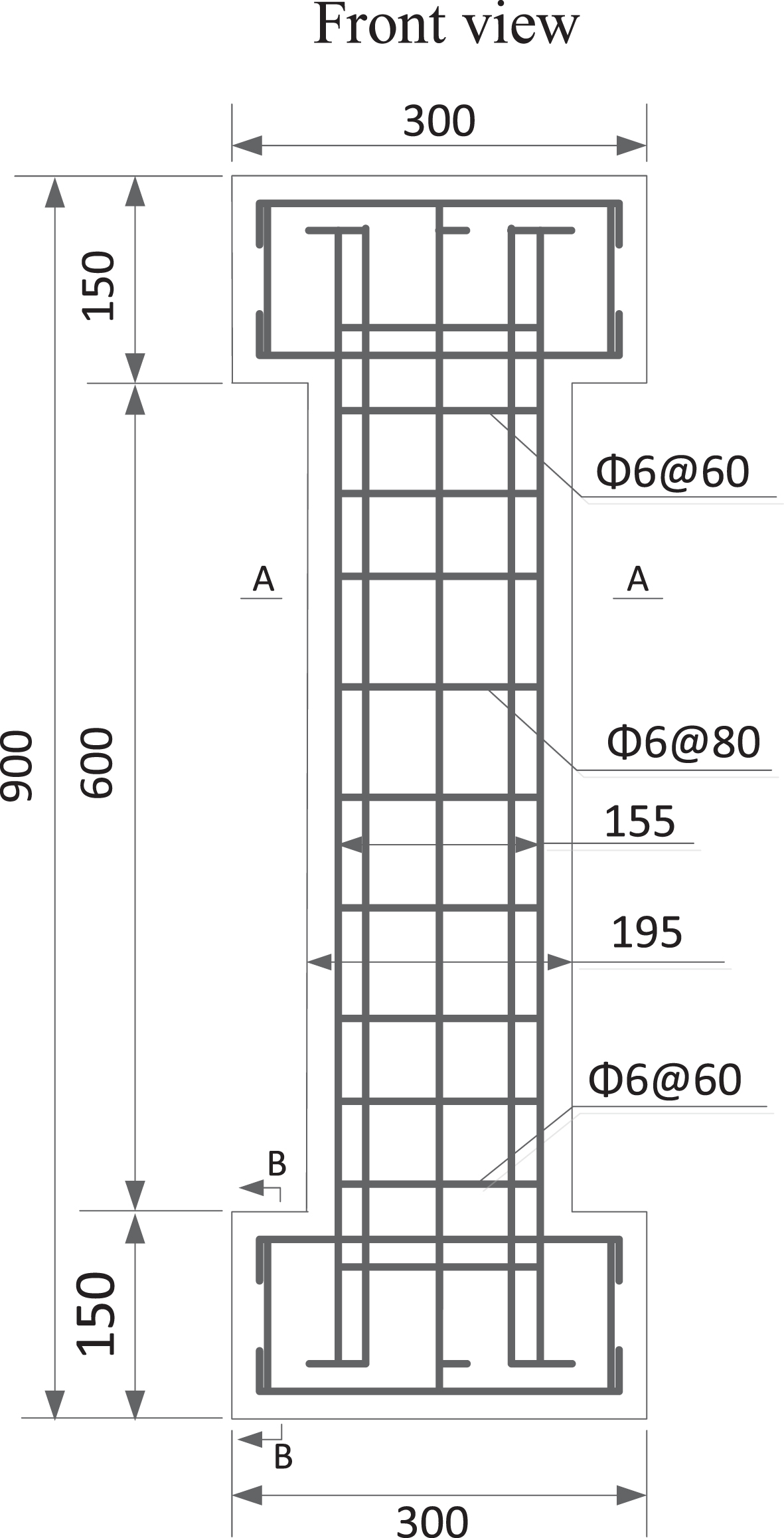
Fig. 2
Arrangement of observation planes.
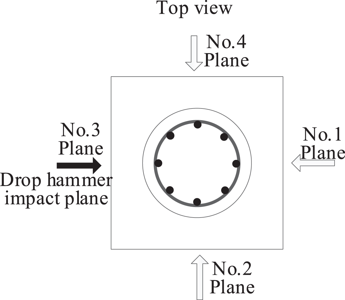
Table 1
Design parameters of specimens
| Specimen number | Target corrosion rate (%) | Method of reinforcement corrosion |
| P1 | 0 | No corrosion |
| P2 | 2 | Drying-wetting cycle and chloride ion corrosion |
| P3 | 5 | Drying-wetting cycle and chloride ion corrosion |
| P4 | 5 | Drying-wetting cycle and chloride ion corrosion |
| P5 | 10 | Drying-wetting cycle and chloride ion corrosion |
| P6 | 10 | Drying-wetting cycle and chloride ion corrosion |
2.1.2Specimens making
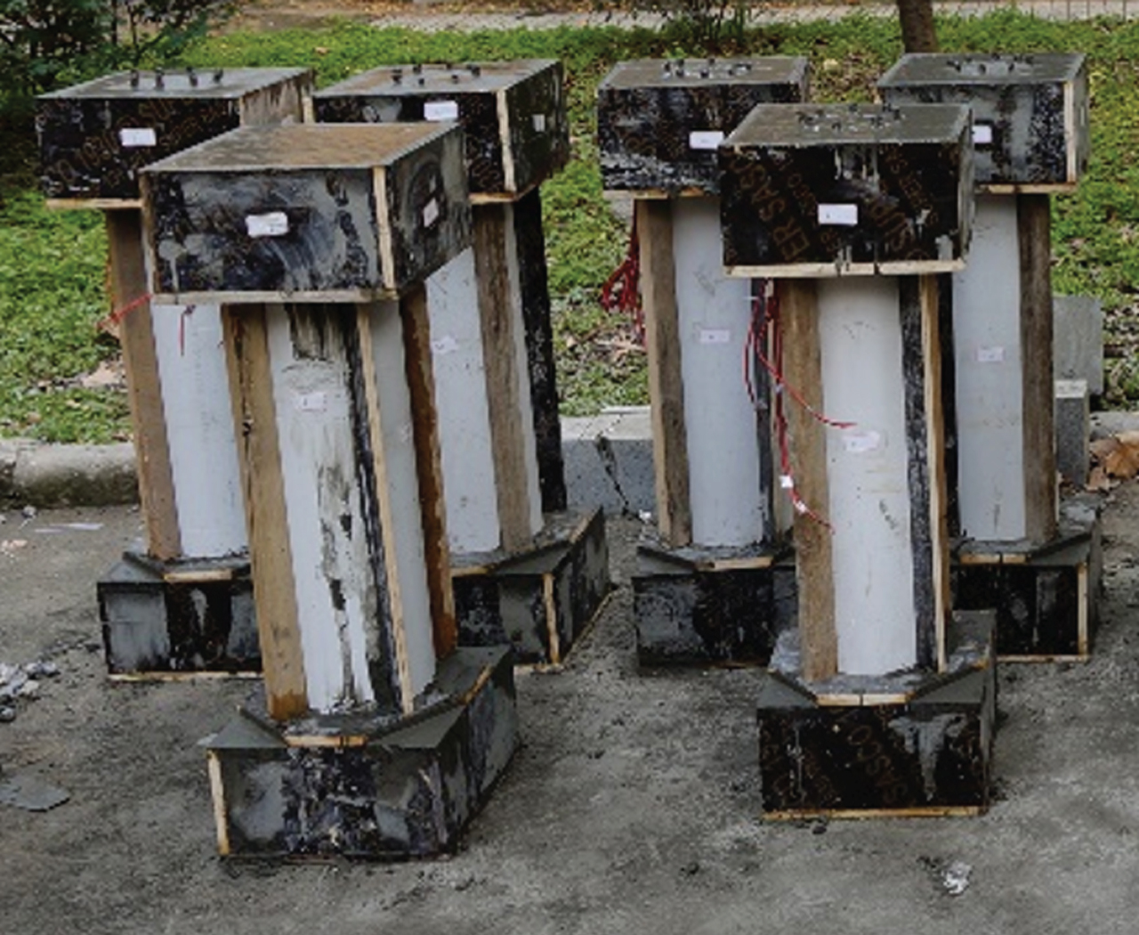
The strength of concrete was C30. Cement was 32.5 grades ordinary Portland cement. Maximum particle size of gravel was 20 mm. Water-cement ratio of the concrete was 0.41. The mix ratio was cement: sand: stone: water: antifreeze agent = 1 : 1.16 : 2.47 :0.36 : 0.05. 6 standard cube test blocks with an edge length of 150 mm were poured with specimens in the same batch. When the curing age reached 28d, the compressive strength test of the concrete standard cube test block was carried out according to the specification, and the actual compressive strength of the test block was 44.12 MPa. The mechanical properties of the steel bars were shown in Table 2. The specimens were poured in the same batch, as shown in Fig. 3.
Table 2
Mechanical properties of steel bars
| Type | Diameter (mm) | Yield strength (MPa) | Ultimate strength (MPa) |
| HRB335 | 10 | 355.626 | 538.245 |
| HPB235 | 6 | 230.677 | 384.460 |
Fig. 3
The cast specimens.
2.2Drying-wetting cycle and chloride ion corrosion test
2.2.1Test device
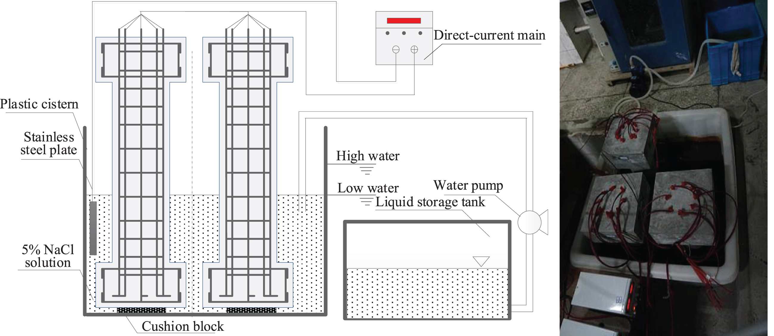
Currently, there are no corresponding specifications or operating procedures for the test of drying-wetting cycle and chloride ion corrosion on reinforced concrete structure. In this experiment, the actual application environment of the cross-sea bridge pier was considered. According to the actual situation of the laboratory, a device was designed to achieve the effect of drying-wetting cycle and chloride ion corrosion by periodically changing the water level of the chloride ion solution, as shown in Fig. 4. In this device, the method of electric acceleration was used to accelerate the corrosion of longitudinal bars of specimens. Meanwhile, the drying-wetting cycle was realized by controlling the water level of NaCl solution periodic change. Finally, specimens with different corrosion rates were obtained.
Fig. 4
Experimental device of drying-wetting cycle and chloride ion corrosion.
2.2.2Measured corrosion rate
When the drying-wetting cycle and chloride ion corrosion experiment was completed and after the lateral impact load test of the drop hammer, the steel bars were removed to accurately weigh and record the residual weights of the corroded steel bars. The number of drying-wetting cycle and measured corrosion rate of steel bars for each specimen were shown in Table 3.
Table 3
Number of drying-wetting cycles and measured corrosion rate of steel bars
| Specimen number | P2 | P3 | P4 | P5 | P6 |
| Number of drying-wetting cycle | 6 | 14 | 14 | 28 | 28 |
| Measured corrosion rate (%) | 3.1 | 5.9 | 4.8 | 10.1 | 10.2 |
2.3Lateral impact test of corroded pier
2.3.1Test setup
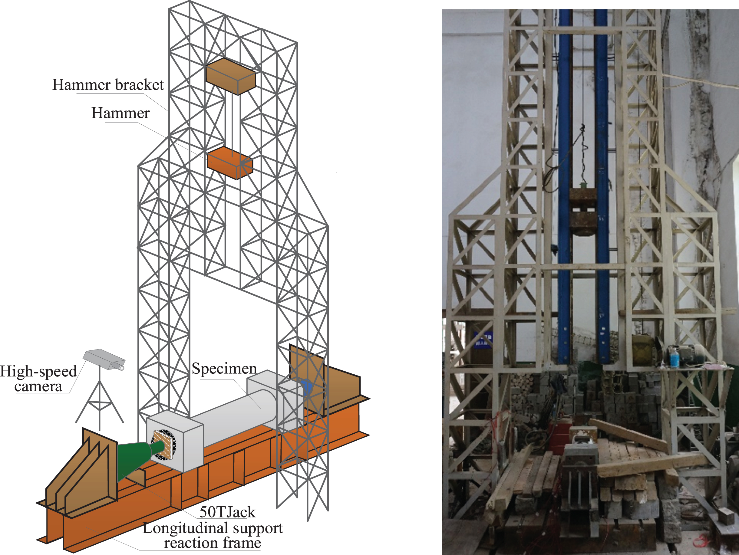
In this experiment, the impact test of drop hammer was used to study the performance of corroded piers subjected to lateral impact. The test setup was shown in Fig. 5.
Fig. 5
Drop hammer impact test setup.
2.3.2Loading
The mass of the drop hammer, Mdh, was 105.3 kg. The impact height, Hdh, was defined as the vertical distance from the bottom of the drop hammer to the top of the impact pad block. The axial force, N, was 240 KN. By changing the impact height of the drop hammer, the specimen was loaded with multiple lateral impacts until it was destroyed completely. The corresponding loading parameters of different working conditions (WC1-WC5) were shown in Table 4. The working conditions of different specimens from first to four stages were the same, and the impact height X of the working condition 5 was determined by the specific damage of each specimen. After each impact, the shape and width of each crack on the specimen was recorded.
Table 4
Loading parameters for different working conditions
| Working condition | Hdh (m) | Mdh (kg) | N (KN) |
| WC1 | 0.66 | 105.3 | 240 |
| WC2 | 1.00 | 105.3 | 240 |
| WC3 | 2.00 | 105.3 | 240 |
| WC4 | 3.00 | 105.3 | 240 |
| WC5 | X | 105.3 | 240 |
2.4Test results
2.4.1Crack propagation progress and failure modes
In order to compare the crack propagation progress and failure modes of the piers with different corrosion rates after subjected to lateral impact, the non-corrosive specimen, P1, and corroded specimens, P2, P4 and P6 were compared and studied, respectively.
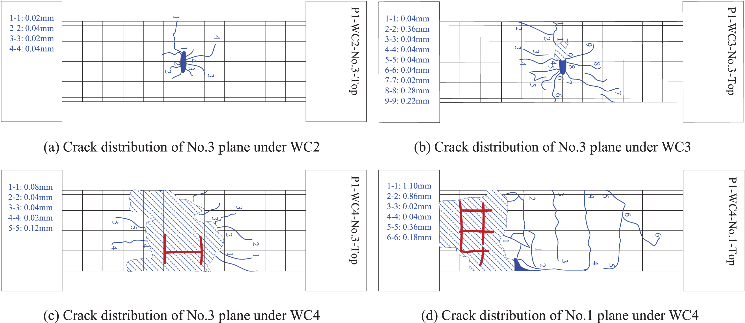
2.4.1.1Non-corrosive specimen: A total of 4 drop hammer impacts (WC1-WC4) were carried out on P1 specimen. After WC1, only 2 short cracks were appeared on the No.3 plane and the maximum crack width was 0.04 mm. After WC2, four cracks were radially distributed in the impact zone of No.3 plane. The cracks spread radially outward around the impact zone after WC3, with 9 cracks being observed and the maximum width of the crack increased to 0.36 mm. Oblique cracks extending from the impact zone to the support appeared on the No.2 and No.4 planes. The maximum crack width was 0.38 mm. After WC4, concrete was crushed in the impact zone and the large block stripping fell off along the oblique shear crack direction. The internal longitudinal bar and hoop were exposed, and the longitudinal bar of the impact plane was bent. Longitudinal cracks and oblique cracks were further expanded from the impact zone to the two ends of the pier, with the maximum crack width being of 1.2 mm. The concrete at one end of the No.1 plane was also peeled off, and the crack with maximum width of 0.86 mm appeared through the transverse bending of the pier. Representative crack distributions of specimen P1 are shown in Fig. 6(a)-(d). The blue solid line indicates the crack in the pier. The slash shadow area is the concrete peeling area. The blue shadow area is the impact area. The red coarse line indicates the exposed steel bar inside the pier.
Fig. 6
Crack distribution of specimen P1.
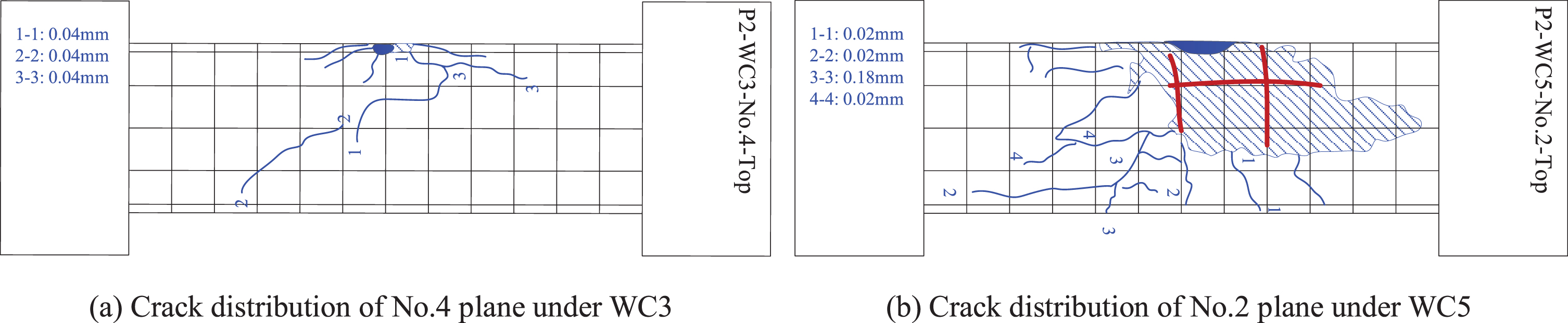
2.4.1.2Low corrosion rate specimen: The crack propagation process and failure mode of P2 specimen with corrosion rate of 3.1% were studied. A total of 5 drop hammer impacts (WC1-WC5) were carried out on P2 specimen. After WC1, 7 fine and radial cracks around the impact zone can be observed on the No.3 plane and the maximum crack width was 0.04 mm. After WC2, the concrete crushing in small area appeared on the No.3 plane and the width of crack increased to 0.16 mm. After WC3, the cracks on the No.3 plane were observed increase in number and width, with crack width increased to 0.42 mm. The oblique cracks from the impact zone of upper surface to the bottom of the corrosion zone can be observed on the No.4 plane, and the maximum crack width was only 0.04 mm with the angle of 45° from the horizontal direction. After WC4, the concrete in the pressurized zone was peeled off and the steel bar in impact zone was exposed, and the side oblique shear crack and the transverse bend crack appeared simultaneously. For WC5, the impact height was 2.00 m. The concrete on both sides of the pier showed different degrees of spalling, and the oblique shear cracks and transverse cracks continued to expand until connected through the whole pier. After WC5, the specimen was shown as the bending shear failure which is controlled by the oblique shear crack and the transverse bending crack. Representative crack distributions of specimen P2 are shown in Fig. 7(a)-(b).
Fig. 7
Crack distribution of specimen P2.
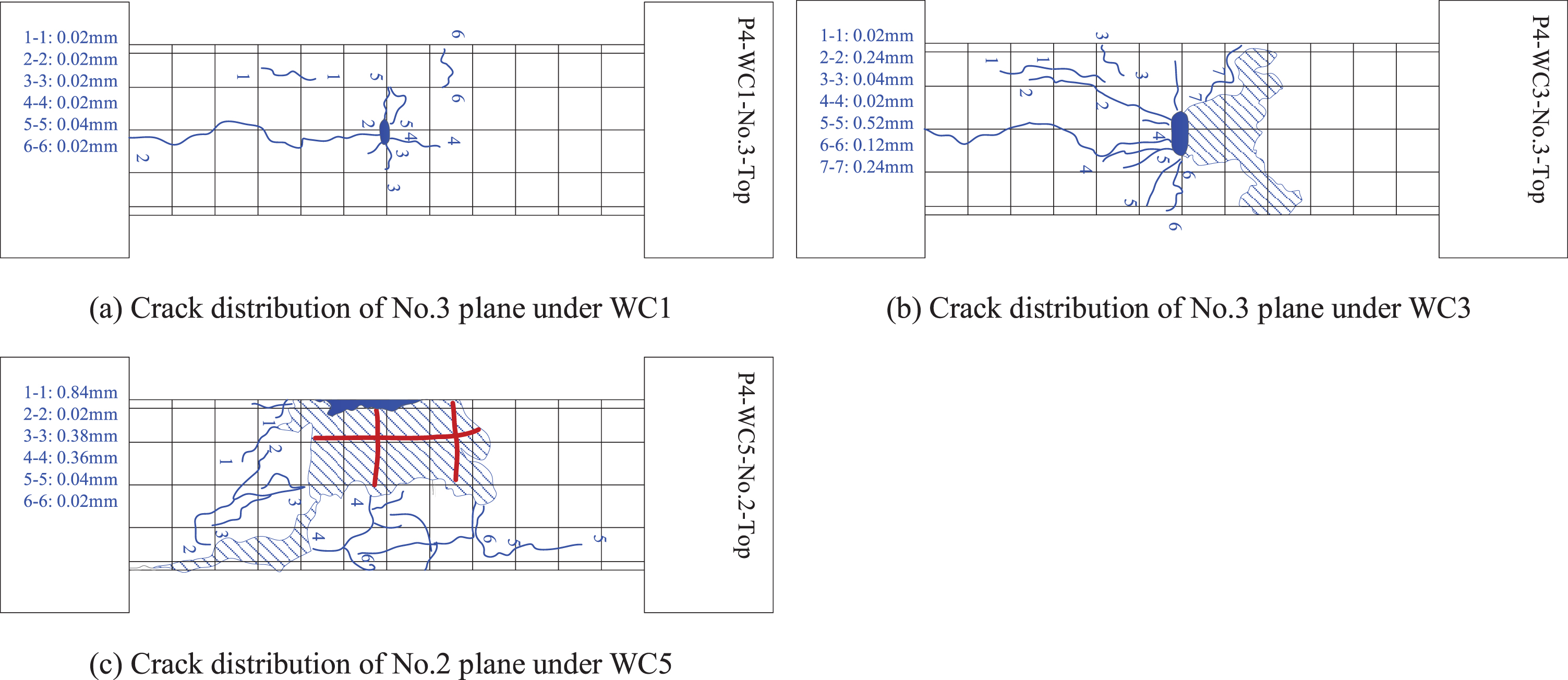
2.4.1.3Medium corrosion rate specimen: The crack propagation process and failure mode of P4 specimen with corrosion rate of 4.8% were studied. A total of 5 drop hammer impacts (WC1-WC5) were carried out on P4 specimen. After WC1, 1 crack along the longitudinal bar can be observed extending from the impact zone to the bottom of the pier column. The fine cracks in the impact zone were radial, and the maximum width of the crack was 0.04 mm. After WC2, more cracks were observed in the impact zone and the maximum crack width increased to 0.18 mm. After WC3, the crushing and peeling of concrete appeared in the impact zone. Two main oblique cracks can be observed on the No.2 plane and its maximum crack width was 0.48 mm. After WC4, the protective layer of concrete in the impact zone was seriously peeled off and the oblique cracks continued to develop on the side of pier. After WC5, in the compression zone of concrete, large blocks peeled off along the direction of oblique shear. Longitudinal bar and stirrups in the impact zone exposed and 2 stirrups fractured. The oblique shear crack, transverse bending crack and longitudinal crack were interlocked. The maximum crack width was 0.84 mm. Representative crack distributions of specimen P4 are shown in Fig. 8(a)-(c).
Fig. 8
Crack distribution of specimen P4.
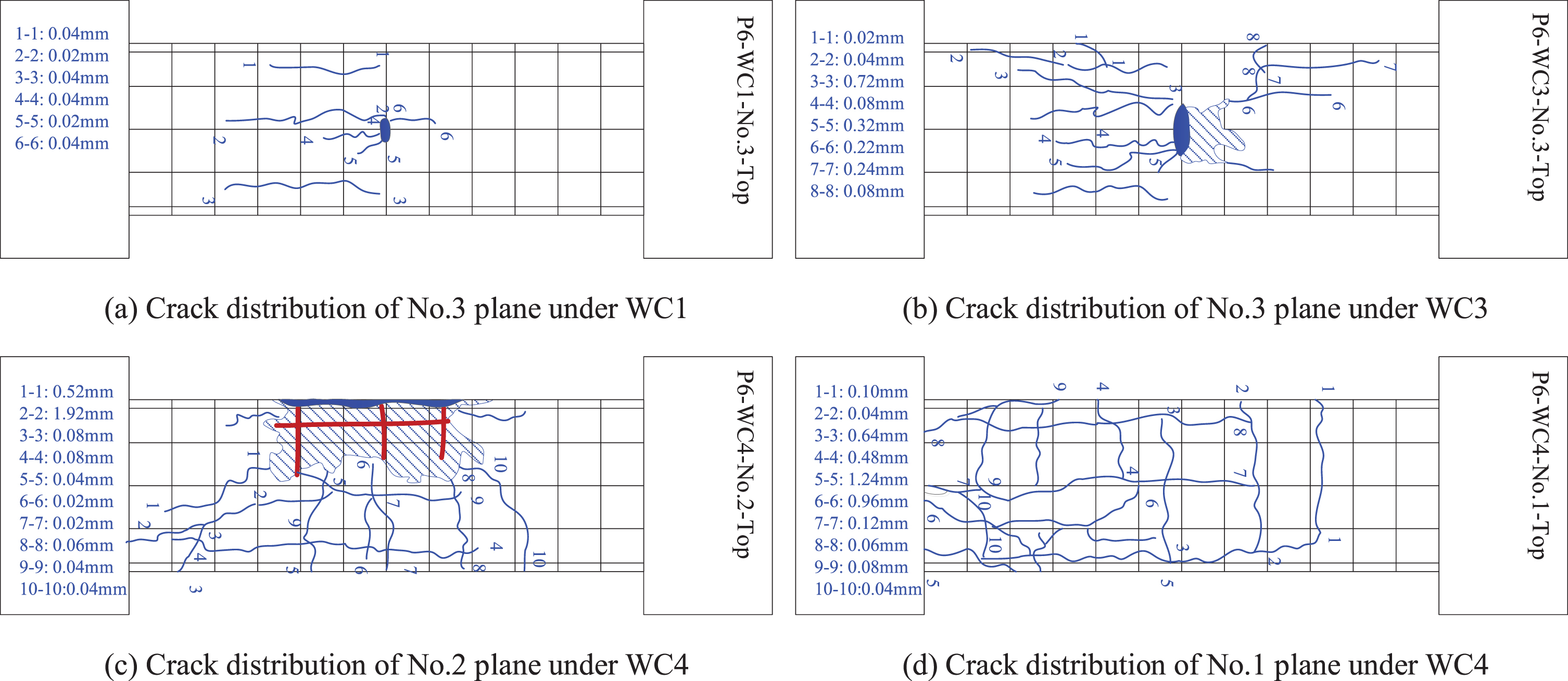
2.4.1.4High corrosion rate specimens: The crack propagation process and failure mode of P6 specimen with corrosion rate of 10.1% was studied. A total of 4 drop hammer impacts (WC1-WC4) were carried out on P6 specimen. After WC1, 6 fine cracks along steel bar with a maximum crack width of 0.04 mm could be observed on the No.3 plane. After WC2, the cracks were radially distributed along the impact zone, and the crack width increased to 0.12 mm. After WC3, concrete peeling slightly in the impact zone of the specimen. Cracks on the No.3 plane continued to expand. The width increased to 0.72 mm. On the No.4 plane, 6 oblique cracks which tended to be horizontal and with the maximum width of 0.08 mm could be observed. After WC4, large blocks of concrete were stripped off and steel bar was exposed. Many oblique shear cracks and transverse bending cracks appeared in the corroded zone of the pier. The maximum crack width was 1.92 mm. Rust expand cracks along longitudinal bars could also be observed. Representative crack distributions of specimen P6 are shown in Fig. 9(a)-(d).
Fig. 9
Crack distribution of specimen P6.
2.4.2Failure modes of piers
The failure of non-corrosive reinforced concrete pier under lateral impact is a process in which the cracks develop gradually from the impact zone uniformly to both ends of the specimen with the increase of impact height. The failure mode is the bending shear failure caused by the joint development of transverse bending cracks in the tensile zone of the specimen and oblique shear cracks in the shear span zone.
Failure mode of the specimen with low corrosion rate is also the bending shear failure controlled by both transverse bending crack and oblique shear crack. Different from non-corrosive specimen, the crack width of specimen with low corrosion rate is smaller than that of non-corrosive specimen under same working condition, and the impact numbers of the specimen bearing impact load is more than that of non-corrosive specimen. The crack propagation process changes from uniform to both ends of specimen to the corroded end of specimen. Main reason for this phenomenon is that when the steel bar has a small amount of corrosion, the corrosion products produced fill the gap between the steel bar and concrete, thus enhancing the bonding force between steel bar and concrete and improving the anti-lateral impact performance of specimen.
Failure mode of the specimen with medium corrosion rate is the bending shear failure controlled by oblique shear cracks. Compared with non-corrosive and low-corroded specimens under the same working conditions, with the increase of corrosion rate, the crack width of specimen increased, but the number of cracks decreased. With the increase of impact height, the oblique shear crack of specimen developed rapidly, and the crushed concrete of specimen also developed further from impact zone, resulting in spall along the oblique shear area, and finally leaded to the bending shear failure of specimen dominated by the oblique shear cracks.
Under multiple lateral impacts, a large number of cracks along the longitudinal bar direction and transverse bending and oblique shear cracks through the specimen were appeared on the specimen with high corrosion rate. The failure mode was the joint action of bending shear cracks and rust expansion cracks. The main reason for this failure mode is that, with the increase of corrosion degree of reinforcement, the increase of expansion products leads to the decrease of bond performance between reinforcement and concrete, and produce rust expansion cracks along direction of the longitudinal bar, which reduces the lateral impact resistance of the specimen.
3Numerical analysis
3.1Finite element model
Finite element models of piers were established using ANSYS. The material type, element type and element number of each part in the model were shown in Table 5.
Table 5
Material type, element type and element number of each part
| Part | Material type | Element type | Element number |
| Longitudinal steel bar | Φ10 | Beam161 | 1696 |
| Stirrup | Φ6 | Beam161 | 1296 |
| Concrete | C30 | Solid164 | 98440 |
| Drop hammer | Steel (The rigid block) | Solid164 | 585 |
| Pedestal | Steel (The rigid block) | Shell163 | 3 |
In this study, the reinforced concrete piers included non-corrosive pier and drying-wetting cycle and chloride ion corrosion piers. There were no cracks in the concrete surface of the non-corrosive reinforced concrete pier. But for corroded specimens, there were cracks along the longitudinal steel bar on the concrete surface. Therefore, the micro-cracks which along the longitudinal steel bars were preset in the geometric model. The geometric models were shown in Fig. 10.
Fig. 10
Geometric models of the reinforced concrete pier.
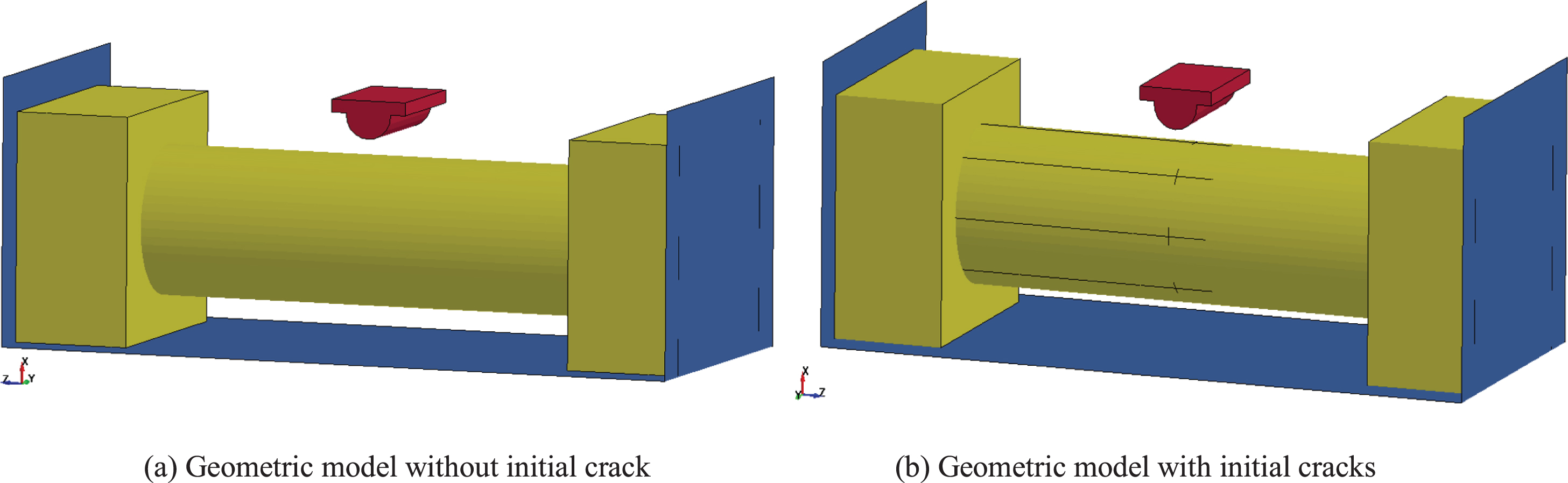
In the geometric model, the length of longitudinal steel bar is 82 cm. For the drying-wetting cycle and chloride ion corrosion specimens, all the longitudinal bars in the position of 0–35 cm belongs to chloride ion corrosion segment, 35–46 cm belongs to the drying-wetting cycle and chloride ion corrosion segment, 46–82 cm belongs to non-corrosive segment. In order to simulate the different segments, the longitudinal bars in the model are modeled in segments and given different diameters.
3.2Constitutive parameters of the material
Constitutive parameters of the steel material were shown in Table 6. Concrete damage constitutive model (#MAT72R3) developed by Karagozian & Case, Inc., also known as K&C constitutive model, was used for concrete. Computational parameters of concrete damage constitutive model were shown in Table 7.
Table 6
Constitutive parameters of steel material
| Parts | Constitutive model | P (kg/m3) | E (pa) | μ | Etan (pa) | σy (pa) | C | P | β | Fs |
| Longitudinal bar | #MAT3 | 7850 | 2.0E11 | 0.30 | 4.48E9 | 3.35E8 | 40 | 5 | 0 | 0.15 |
| Stirrup | #MAT3 | 7850 | 2.1E11 | 0.27 | 4.48E9 | 2.35E8 | 40 | 5 | 0 | 0.15 |
| Drop hammer | #MAT20 | 7850 | 2.1E11 | 0.27 | / | / | / | / | / | / |
| Pedestal | #MAT20 | 7850 | 2.1E11 | 0.27 | / | / | / | / | / | / |
Table 7
Computational parameters of concrete damage constitutive model
| Parameter | ρ (kg/m3) | μ | ft (pa) | a0 | Rsize (in/m) | UCF (psi/m) |
| Numerical value | 2500 | 0.2 | 3.4E6 | 0.79 | 39.37 | 1.45E-4 |
3.3Numerical simulation of different factors on performance of pier
In order to study the performance of reinforced concrete piers under lateral impact in marine environment, the effects of various factors on the performance of reinforced concrete piers were analyzed in turn from the aspects of impact velocity, impact mass, compressive strength of concrete and impact number. Yang et al. [20] compared the numerical simulation results with the experimental results in terms of the time history value of reinforcement strain of the corroded reinforced concrete pier. The feasibility and the validity of the numerical simulation are validated.
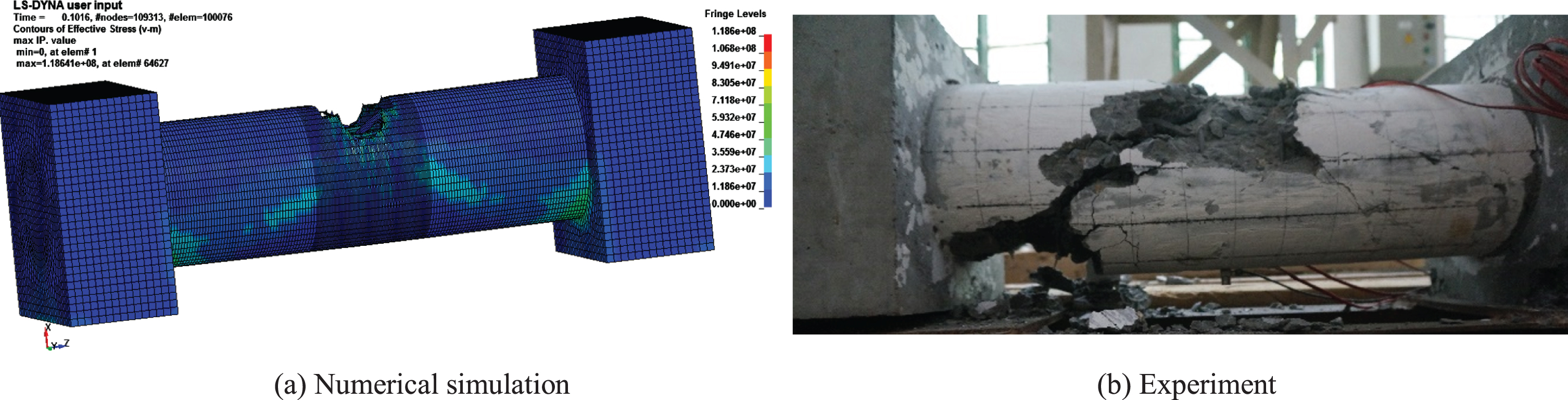
On the other hand, we compared the damage results between numerical simulation and experiment. In order to further verify the feasibility of numerical simulation, we carried out numerical simulation on P1 specimen corresponding to impact test WC1-WC4. After WC4, the damage results of numerical simulation and experiment were shown in Fig. 11 (a) and (b) respectively. By comparing the damage results of P1 specimen obtained by numerical simulation and experiment, it can be seen that the damage was basically the same and was as follows: In the impact zone, concrete was crushed and large pieces spalled off. There were obvious oblique cracks extending from the impact zone to both ends of the pier. The coterminous part of pier column and abutment appeared to be damaged. Therefore, numerical simulation can be used to study the influence of various factors on the performance of corroded piers under impact.
Fig. 11
Damage results of P1 specimen.
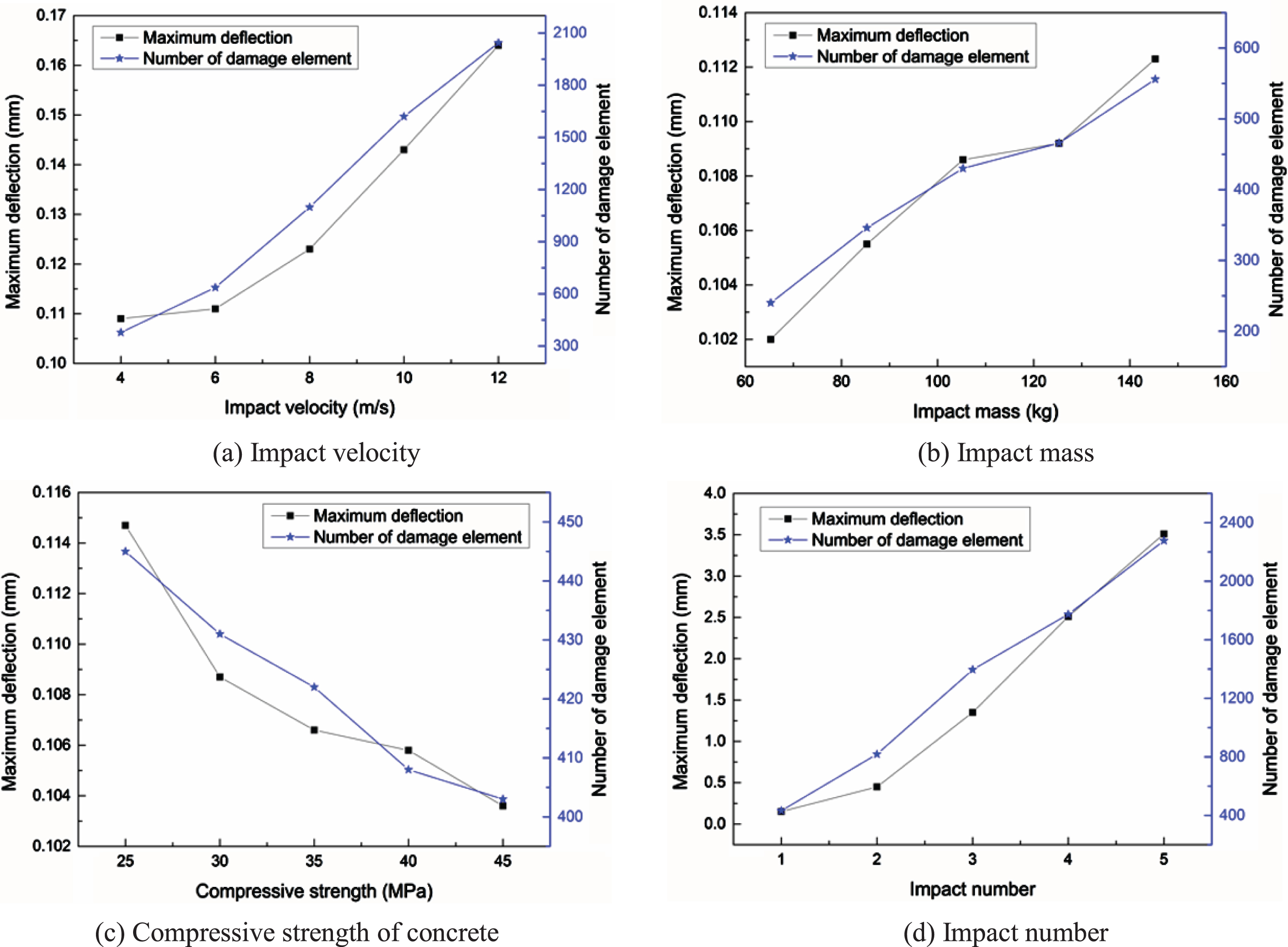
In order to comprehensively and accurately compare and investigate the influence of various factors on the performance of corroded piers, the standard working condition was set as follow: the corrosion rate of the longitudinal bar was 2.5%, the impact mass was 105.3 kg, the impact height was 0.03 m, the impact velocity was 4 m/s, the style of the impact contact surface was convex, the diameters of the longitudinal bar and stirrup were 10 mm and 6 mm respectively, the compressive strength of concrete was 30 MPa. After each impact, the number of damage elements and maximum deflection were recorded. The influence of different factors on maximum deflection and number of damage element of pier was shown in Fig. 12. In ANSYS/LS-Dyna calculation, failure criteria were used to judge whether the element failed, and the failed element was called damage element.
Fig. 12
Influence of different factors on maximum deflection and number of damage element of pier.
3.3.1Impact velocity
In order to study the effect of impact velocity on performance of pier, the impact velocity was changed under the condition that other conditions in standard working condition were unchanged. Then, numerical simulation was carried out with the impact velocity of 4 m/s, 6 m/s, 8 m/s, 10 m/s and 12 m/s respectively. The number of damage element and the maximum deflection of the pier at different impact velocities were shown in Fig. 12(a).
It can be seen from Fig. 12(a), with the increase of the impact velocity, the number of damage element and maximum deflection of the pier increased significantly. Compared with the standard working condition (impact velocity of 4m/s), when the impact velocity was 1.5, 2, 2.5 and 3 times of the impact velocity under standard working condition, the maximum deflection of the pier increased by 1.5%, 12.9%, 31.7% and 50.6%. When the impact velocity increased from 4 m/s to 6 m/s, 8 m/s, 10 m/s and 12 m/s, the number of damage elements increased by 0.68, 1.90, 3.29 and 4.40 times, respectively. Numerical simulation results showed that increasing the impact velocity will obviously increase the damage of lateral impact on the corroded pier.
3.3.2Impact mass
In order to study the effect of impact mass on performance of pier, the impact mass was changed under the condition that other conditions in standard working condition were unchanged. Then, the numerical simulation was carried out with the impact mass of 65.3 kg, 85.3 kg, 105.3 kg, 125.3 kg and 145.3 kg respectively. The number of damage element and the maximum deflection of the pier under different impact mass were shown in Fig. 12(b).
It can be seen from Fig. 12(b) that the number of damage elements and the maximum deflection of the pier changed with the change of impact mass. Compared with the standard working condition (impact mass of 105.3 kg), when the impact mass decreased by 19% (85.3 kg) and 38% (65.3 kg) respectively, the maximum deflection of the pier decreased by 2.9% and 6.1%, while the impact mass increased by 19% (125.3 kg) and 38% (145.3 kg) respectively, the maximum deflection of the pier increased by 0.6% and 3.5% respectively. From Fig. 12(b), it also can be seen that the number of damage elements increased significantly with the increase of the impact mass. The impact mass increased from 65.3 kg to 145.3 kg, the number of damage element increased from 240 to 556, increased by 1.3 times. It is concluded that the impact mass affects the performance of the corroded pier under the lateral impact, and with the increase of the impact mass, the impact damage of the corroded pier becomes larger.
3.3.3.Compressive strength of concrete
In order to study the effect of concrete compressive strength on the performance of pier, the compressive strength of concrete was changed under the condition that other conditions in standard working condition were unchanged. Then, numerical simulation was carried out with the compressive strength of 25 MPa, 30 MPa, 35 MPa, 40 MPa and 45 MPa respectively. The number of damage element and the maximum deflection of the pier under different concrete compressive strength were shown in Fig. 12(c).
As can be seen from Fig. 12(c), changing the compressive strength of concrete will affect the maximum deflection and the number of damage element of corroded pier under lateral impact, but with less degree. Compared with the standard working condition (concrete compressive strength of 30 MPa), the maximum deflection of pier with concrete compressive strength of 25 MPa increased by 5.5%, while the maximum deflection of piers with concrete compressive strength of 35 MPa, 40 MPa and 45 MPa decreased by 1.9%, 2.8% and 4.6%, respectively. With the increase of concrete compressive strength from 25 MPa to 45 MPa, the number of damage element decreased from 445 to 403, decreased by 9.44%. In conclusion, it can be concluded that, the compressive strength of concrete has little influence on the performance of corroded pier under lateral impact.
3.3.4Impact number
In order to study the influence of impact number on the performance of corroded pier, the pier was impacted five times under standard working condition. The number of damaged element and the maximum deflection of pier were recorded after each impact and as shown in Fig. 12(d).
As can be seen from Fig. 12(d), the impact number has a great influence on the number of damage element and the maximum deflection of the pier. Increasing the impact number, the maximum deflection and the number of damage element of the pier both increased obviously. When the impact number increased from 1 to 2, 3, 4 and 5, the maximum deflection of the pier increased by about 2.2, 8.8, 15.8 and 26.3 times, respectively. It can be concluded that when the impact number was small (≤2), there was a linear relationship between the increase times of deflection and the impact number, but when the impact number was more than 2, there was a linear relationship between the increase times of deflection and the square of impact number. When the impact number increased from 1 to 2, 3, 4 and 5, the number of damage element increased from 432 to 818, 1396, 1774 and 2277, increased by about 1, 2.2, 3.1 and 4.3 times, respectively. In conclusion, the impact number has significantly influence on the performance of corroded pier under lateral impact.
4Discussion
In this research, the influence of lateral impact load on the response of corroded piers were studied through experiments and numerical simulation. It was concluded that the corrosion rate, compressive strength of concrete, impact number and impact velocity all affect the response of corroded piers. In addition to the parameters studied in this paper, scholars also studied the influence of other parameters on the response of specimens under impact load. Based on the experiments and nonlinear finite element analysis, Sha and Hao [21, 22] studied the shape, diameter and height of pier on the response due to impact load. They obtained the impact pattern of circular reinforced concrete piers was different from the square pier impact cases in which the peak impact force strongly depends on the pier dimension. For the circular pier, the impact force increased with the increase of pier diameter, but the changes in the amplitude were not significant. In addition, the pier height effect was also insignificant to the peak impact force. Liu [23] obtained the failure mode of piers affected by the ratio of height to diameter through the experiment of lateral impact on circular reinforced concrete column. Based on the experimental study, Cai et al. [24] obtained the specimens with larger cross-section dimension have plumper impact force versus time curve and the enhancement of slenderness ratio of specimen leads to the decreasing of flexural stiffness and suffer more severe damage. Tian et al. [25] found that the reduction of transverse reinforcement spacing would reduce the peak lateral displacement and residual displacement of columns under impact load. Based on the experimental investigation, Wang et al. [26] found the main influence factor on the failure mode of RC columns was stirrup spacing. The column was prone to shear failure when the stirrup spacing was large otherwise to flexural failure. These studies show that the size, geometry and stirrup spacing of the pier will have an impact on the response of the pier under impact load. And the above studies were carried out on non-corroded components. Due to the initial damage, the performance of corroded components may be different from that of non-corroded components. Therefore, the influence of these parameters on the response of corroded piers under impact load should also be studied. This is the deficiency of this paper, which should be studied in the future research.
On the other hand, the failure modes of specimens will be different under different loading modes. Saatci [27] found beams with bending failure under static load may also suffer shear failure under impact load. Based on the static load test and drop hammer impact test on corroded beam specimens, Yang [28] concluded that the specimen with bending failure under static load may change its failure mode under impact load and show both bending and shear failure characteristics. Liu et al. [29] carried out static load and impact load on two reinforced concrete column specimens respectively, and concluded that the failure modes of the columns under the two loading modes were different. The failure modes of the columns under static load and impact load were bending failure and shear failure respectively. Therefore, in order to better study the dynamic response of corroded piers, the failure modes under different loading modes should also be compared for corroded piers. In this paper, only the failure modes under impact load were studied. The comparative study of the failure modes under static load and impact load is necessary to be studied in the future.
5Conclusions
In this paper, reinforced concrete pier specimens with different corrosion rates were obtained by drying-wetting cycle and chloride ion corrosion test. Based on the drop hammer impact test, the crack propagation process and failure mode of piers were studied by cumulative impact on the specimens with different corrosion rates by changing the impact height. Then the finite element model was established by using ANSYS/Ls-Dyna software, and the influences of various factors on the performance (the maximum deflection and the number of damage elements) of corroded piers were studied in terms of the impact velocity, impact mass, compressive strength of concrete and impact number. Based on the experimental and numerical analysis, the following conclusions are drawn from this paper:
(1) The failure modes of specimens with different corrosion rate under lateral impact load were different. The failure mode of the non-corrosive specimen and the low corrosion rate specimen was destroyed by the bending shear which was jointly controlled by the transverse bending crack and the oblique shear crack. The failure mode of medium corrosion rate specimen was the bending shear failure caused by oblique shear crack, and the high corrosion rate specimen was the failure mode of the joint action of bending shear crack and rust expansion crack. In this experiment, the maximum corrosion rate was about 10%. The failure mode of pier specimen with corrosion rate greater than 10% under impact load needs to be further studied through experiments.
(2) The increase of impact velocity, impact mass and impact number will increase the damage of corroded pier under impact, but the increase degree is different. The damage of corroded piers by repeated impact is very large, so it is very necessary to check and maintain the corroded piers under repeated impact.
(3) Increasing the compressive strength of concrete will reduce the damage of corroded pier under impact, but with less degree. More research is needed on measures to reduce damage caused by impact on corroded piers.
Conflict of interest
None to report.
Funding
This research was supported by the National Natural Science Foundation of China (51178264), the Shanghai Science and Technology Commission (18070502900), and the Shanghai Shentong Metro Group Co., Ltd. (JS-KY17R008).
References
[1] | Yokota H , Kato E , Iwanami M . Chloride-induced corrosion of reinforcement and its effect on performance of structures. International Journal of Modelling, Identification and Control. (2009) ;7: (2):179–84. DOI: 10.1504/IJMIC.2009.027072 |
[2] | Guo AX , Li HT , Ba X , Guan XC , Li H . Experimental investigation on the cyclic performance of reinforced concrete piers with chloride-induced corrosion in marine environment. Engineering Structures. (2015) ;105: :1–11. DOI: 10.1016/j.engstruct.2015.09.031 |
[3] | Gao SB , Ikai T , Ni J , Ge HB . Load-carrying capacity degradation of reinforced concrete piers due to corrosion of wrapped steel plates. Steel and Composite Structures. (2016) ;20: (1):91–106. DOI: 10.12989/scs.2016.20.1.091 |
[4] | Kashani MM , Lowes LN , Crewe AJ , Alexander NA . Computational modelling strategies for nonlinear response prediction of corroded circular RC bridge piers. Advances in Materials Science and Engineering. (2016) ;2016: :1–15. DOI: 10.1155/2016/2738265. |
[5] | Jin WL , Zhao YX . Durability of Concrete Structures. Beijing: Science press, (2002) . |
[6] | Sahmaran M , Erdem TK , Yaman IO . Sulfate resistance of plain and blended cements exposed to wetting-drying and heating-cooling environments. Construction and Building Materials. (2007) ;21: (8):1771–8. DOI:10.1016/j.conbuildmat.2006.05.012. |
[7] | Erdoğdu Ş , Bremner TW , Kondratova IL . Accelerated testing of plain and epoxy-coated reinforcement in simulated seawater and chloride solutions. Cement and Concrete Research. (2001) ;31: (6):861–7. DOI: 10.1016/S0008-8846(01)00487-2 |
[8] | Wei J , Fu XX , Dong JH , Ke W . Corrosion evolution of reinforcing steel in concrete under dry/wet cyclic conditions contaminated with chloride. Journal of Materials Science & Technology. (2012) ;28: (10):905–12. DOI: 10.1016/S1005-0302(12)60149-2 |
[9] | Su XP , Guo JH . Study on the durability of normal strength concrete under the action of salt corrosion and dry-wet cycles. Advanced Materials Research. (2014) ;919: :1849–52. DOI: 10.4028/www.scientific.net/AMR.919-921.1849. |
[10] | Artigas A , Monsalve A , Sipos K , Bustos O , Mena J , Seco R , Garza-Montes-de-Oca N . Development of accelerated wet-dry cycle corrosion test in marine environment for weathering steels. Corrosion Engineering, Science and Technology. (2015) ;50: (8):628–32. DOI: 10.1179/1743278215Y.0000000007 |
[11] | Melchers RE , Herron C , Emslie R . Long term marine corrosion of cast iron bridge piers. Corrosion Engineering, Science and Technology. (2016) ;51: (4):248–55. DOI: 10.1179/1743278215Y.0000000049 |
[12] | Guo AX , Yuan WT , Li HT , Li H . Structural strength deterioration of coastal bridge piers considering non-uniform corrosion in marine environments. Earthquake Engineering and Engineering Vibration. (2018) ;17: (2):429–44. DOI: 10.1007/s11803-018-0451-z |
[13] | Wang JJ , Chen C . Simulation of damage for bridge pier subjected to ship impact. Engineering mechanics. (2007) ;7: :156–60. |
[14] | Tian L , Zhu C . Numerical simulation of ship-bridge collision based on LS-DYNA technique. Advanced Materials Research. (2011) ;243: :6230–6. DOI: 10.4028/www.scientific.net/AMR.243-249.6230. |
[15] | Zeng P . Theoretical and Experimental Research on Collision Force of Bridge Pier. Master’s thesis. Guangdong University of Technology, Guangzhou, Guangdong, China, (2013) . |
[16] | Liu K , Yang G , Yang K . Research and analysis of ship-bridge collision. Applied Mechanics and Materials. (2014) ;638: :973–6. DOI: 10.4028/www.scientific.net/AMM.638-640.973 |
[17] | Tian L , Huang F . Numerical simulation for progressive collapse of continuous girder bridge subjected to ship impact. Transactions of Tianjin University. (2014) ;20: (4):250–6. DOI: 10.1007/s12209-014-2216-8 |
[18] | Wang JJ , Song YC , Yu ZR . Impact factor method for design of bridge foundations under ship collisions. Advances in Structural Engineering. (2017) ;20: (4):534–48. DOI: 10.1177/1369433216655923 |
[19] | Wan YL , Zhu L , Fang H , Liu WQ , Mao YF . Experimental testing and numerical simulations of ship impact on axially loaded reinforced concrete piers. International Journal of Impact Engineering. (2019) ;125: :246–62. DOI: 10.1016/j.ijimpeng.2018.11.016 |
[20] | Yang S , Xia XZ , Fang CQ . Numerical analysis of lateral anti-impact on the corroded reinforced concrete pier. China Harbour Engineering. (2017) ;37: (12):25–9. |
[21] | Sha YY , Hao H . Nonlinear finite element analysis of barge collision with a single bridge pier. Engineering Structures. (2012) ;41: :63–76. DOI: 10.1016/j.engstruct.2012.03.026 |
[22] | Sha YY , Hao H . Laboratory tests and numerical simulations of barge impact on circular reinforced concrete piers. Engineering Structures. (2013) ;46: :593–605. DOI: 10.1016/j.engstruct.2012.09.002 |
[23] | Liu B . Study on Experiments and Analytical Methods of Axially-Loaded Circular RC Column Under Lateral Impact Loading. Doctor’s thesis. Hunan University, Changsha, Hunan, China, (2019) . |
[24] | Cai J , Ye JB , Chen QJ , Liu XP , Wang YQ . Dynamic behaviour of axially-loaded RC columns under horizontal impact loading. Engineering Structures. (2018) ;168: :684–97. DOI: 10.1016/j.engstruct.2018.04.095 |
[25] | Tian L , Zhu C , Wang H , Feng XH . Dynamic response and failure modes of RC columns under impact. Engineering Mechanics. (2013) ;30: (2):150–5. |
[26] | Wang XG , Zhang YM , Su YP , Feng Y . Experimental investigation on the effect of reinforcement ratio to capacity of RC column to resist lateral impact loading. System Engineering Procedia. (2011) ;1: :35–41. DOI: 10.1016/j.sepro.2011.08.007 |
[27] | Saatci S . Behaviour and Modelling of Reinforced Concrete Structures Subjected to Impact Loads. Doctor’s thesis. University of Toronto, Toronto, Canada, (2011) . |
[28] | Yang Y . Study on Performance of Corroded Reinforced Concrete Beams Under Impact Loading. Master’s thesis. South China University of Technology, Guangzhou, Guangdong, China, (2018) . |
[29] | Liu F , Luo QZ , Yan B , Jiang ZG . Numerical study on the failure mode of RC column subjected to lateral impact. Journal of Vibration and Shock. (2017) ;36: (16):122–7. |