Renovation of the Van Brienenoord Bridge, The Netherlands
Abstract
Part of the Netherlands’ busiest highway, the Van Brienenoord Bridge comprises 12 lanes of traffic split across the eastbound bridge built in the 1960 s and the western bridge built in the 1990 s. The Van Brienenoord Bridge complex consisting of two parallel 300 m span steel arch bridges, approach structures and three parallel bascule bridges over the New Meuse. The bridges carry about 230,000 vehicles daily. A strengthening and replacement strategy was developed to reduce road closures to one of the two bridges at a time and reducing this time to weeks instead of months. The strengthening consists of plate stiffeners to the main girders and arches and a new deck. Construction begins in 2025 and will extend the bridge’s useful life to another 100 years. The strengthening instead of replacing is in line with RWS’ commitment to adopting circular economy principles for their infrastructure network.
1Introduction
1.1The client and design team
The Dutch economy relies heavily on mobility, transport and logistics, the main economic centres must remain accessible. The Dutch mobility policy serves 2 goals: reliable journey times and better accessibility. Motorists travelling in the rush hour must be able to arrive to their destination without delay 95% of the time, despite increased mobility and unexpected congestion.
The Client, Rijkswaterstaat (RWS), the Dutch Directorate-General for Public Works and Water Management, strives among its objectives to improve and maintain their network of highways and waterways. This is a very important task, since various bridges, tunnels and roads date back to the 1950 s and 60 s while in the meantime traffic volumes have risen tremendously and trucks have become heavier which has resulted in increasing pressure on our infrastructure.
In response to fatigue problems observed on steel orthotropic decks, RWS began a refurbishment program of eight major big steel bridges to provide strengthening design and engineering for an extended life of at least 30 years. This work is carried out by a joint venture (JV) of Arup and Royal Haskoning DHV (RHDHV) known as the Managing Contractor (MC). Arup’s role within the MC project includes all technical management activities from pre-inspection plans, 3D modelling of the global and local existing structures up to design of the main structure’s strengthening. The JV along with the client work as a team responsible for the choice and management of the contractor who will complete the works and for the technical tender documents including bridge specific drawings and project specifications.
1.2The Van Brienenoord Bridge
The Van Brienenoord Bridge is a large twin tied-arch motorway bridge in the Netherlands. Located at the east side of Rotterdam, it crosses the New Meuse, a major distributary of the river Rhine. The bridge is a key connection to the Port of Rotterdam.
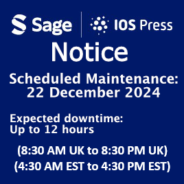
The bridge consists of two separate, parallel, and visually almost identical bowstring-arch-bridges, as well as a set of three parallel bascule bridges on the north end. The eastern arch was built in 1965 (with 2 movable bascule bridges next to each other), and in 1990 the second western arch was added (with 1 movable bascule bridge). The bridges carry 12 lanes of traffic of the A16 motorway, the busiest highway in the Netherlands. Additionally, on the outside of the east arch, a two-way segregated cycling bridge has been mounted. Including lead-up ramps, the Van Brienenoord Bridge is 1320 metres long and vessels with up to 24 meters air draft (distance from the surface of the water to the highest point on a vessel) can pass under the closed bridge. With a span of 295 m, the west arch is the longest span road bridge in the Netherlands. Refer to Figs. 1 and 2 for a plan and elevation of the arch bridges.
Fig. 1
Plan of the Van Brienenoord Bridge existing situation.
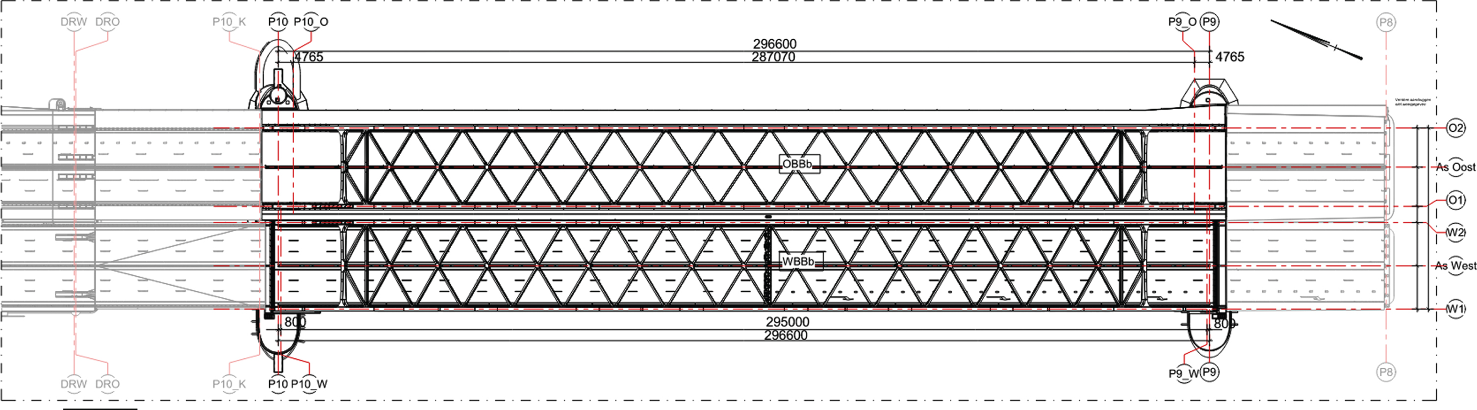
Fig. 2
Elevation of the Van Brienenoord Bridge existing situation.
The arches rise 40.99 m and the width between centrelines of the arches varies from 24.9 m for the older eastern bridge to 27.5 for the newer western bridge.
Of the eight bridges that form part of the refurbishment program, the Van Brienenoord Bridge is the last. Saving the largest of the bridges for last the project benefits from the lessons learned on the seven prior bridges.
The project specific objectives are:
– Sustainability: reuse as much of the existing structures as possible.
– Maintenance of traffic: Minimize partial and complete road closures.
– Health and safety: Reduce the works over water and within enclosed spaces.
1.3Circularity and sustainability at RWS
Circularity in construction involves applying the principles of circular economy to the construction industry. It aims to close building material loops by reusing, sharing, leasing, repairing, refurbishing, upcycling or recycling rather than continuing the traditional linear economy take-make-consume-dispose process. It is about considering how to maximize the lifespan and reusability of entire buildings or materials at the very start of the design process [1].
RWS is committed to the principles of circularity. They are promoting sustainable area development and aim to be energy neutral and working according to the circular principle by 2030. Their commitment is being implemented by procuring a series of pilot projects, actively making knowledge and expertise gained available to target groups in the market. RWS is also a joint instigator of the Circular Building 2023 platform (CB’23), which ensures agreement on measuring methods, construction industry passports as well as circular procurement and circular design.
The Van Brienenoord Bridge does not present itself as a candidate for complete circularity, however, where feasible, the principles are being applied, particularly the extension of service life and the reuse instead of recycling of steel.
2Bridge assessment
Traffic on the Van Brienenoord exceeds 230,000 vehicles crossing the bridge daily, using four 3-lane carriageways, in an express versus local / distributor arrangement. About 120,000 ships pass through each year and the bridge bascule spans open about 100 times per year for higher clearance shipping. The bridge is suffering from fatigue damages caused by the frequency of heavy freight traffic.
During routine maintenance inspections fatigue cracks were identified in the orthotropic deck. Similar damage had been observed in other bridges in the country and is one of the drivers behind the renovation project for the eight steel bridges [2].
The first stage of the project was to assess the existing bridges. The assessment began with a desk study of the as-built documentation followed by instrumentation and surveys to establish the current condition of the bridges. The instrumentation included strain gauges to calibrate the models. The desk study found that the as-built hanger forces (measured during cable installation) did not match the design forces specified by the original designer. This prompted a study to calibrate the new analysis models that better matched the response and prescribing cable jacking to improve the load distribution in these to improve their safety.
From the initial assessments both bridges did not pass the fatigue and static requirements for the next 30 years. For the existing eastern bridge, being almost 60 years old and with its stress history, replacement became the obvious solution. For the western bridge, the newer of the two, strengthening was maintained as a possible solution.
The assessment of the western arch, using the latest Eurocode [3], the Dutch assessment code [9] and the client’s assessment guidelines [5, 6], was performed for a new build service life of 100 years, using a lower reliability index allowed for existing structures in the client’s guidelines. A design service life of 30 years has previously been used for other renovations in the Netherlands. However, for the sustainability ambitions the longer service life was chosen.
All the existing components have been assessed for 100 years using a reliability index (β) [3] of 3.8 instead of 4.3 which required for new build bridges in the Netherlands. This gave the opportunity to re-use more existing steel. All new placed elements are designed to new build. Implications on loads and design situation are discussed and elaborated in Tjepkema et al. [7].
There was a strong will at both Rijkswaterstaat and the engineering firms involved, Arup and Royal Haskoning DHV, to refurbish the Van Brienenoord Bridge in a sustainable way. This led to the current solution; building two new bridges might be more manageable, but from a sustainability perspective, renovation was strongly preferred.
3Western arch bridge optioneering
An optioneering study was undertaken to determine the best course of action for the western arch bridge. The two main paths were to replace the bridge or to strengthen the bridge. The replacement would be straightforward, a new structure designed and built to the latest standards, however the existing structure and its 4700 tons (544 kg/m2) would be scrapped. The strengthening options involved two alternatives for the deck, a high-strength concrete deck overlay or the replacement of the orthotropic deck, both also requiring strengthening of the main structural elements to withstand the increased dead loads, traffic increases and provide sufficient fatigue resistance for a 100-year design life.
A high strength concrete overlay option was developed by RWS and de Jong [8] and while it helps with the fatigue of the orthotropic deck, this would require an execution time of 1.5 years along with the associated health and safety risks of applying the strengthening over water and to a structure subjected to considerable locked in stresses.
The orthotropic bridge replacement option consists in removing the existing deck and replacing it with a more robust steel orthotropic design to meet the latest design criteria [9] (proposed as a Technical Specification on orthotropic bridge decks for the draft update to Eurocode 1993-1-9 [10]). This new deck was estimated to be heavier and thus the rest of the structure would require strengthening and improvements to some of the joint structures to address static and fatigue strength for the extended 100-year design life.
As the deck is an integral part of the bowstring structure the bridge requires unloading to replace the deck. The western bridge was originally built off-site and floated into position. With this in mind the bridge could be floated out to be strengthened in a safer construction site, compared to working over water, and then returned after the strengthening works are completed.
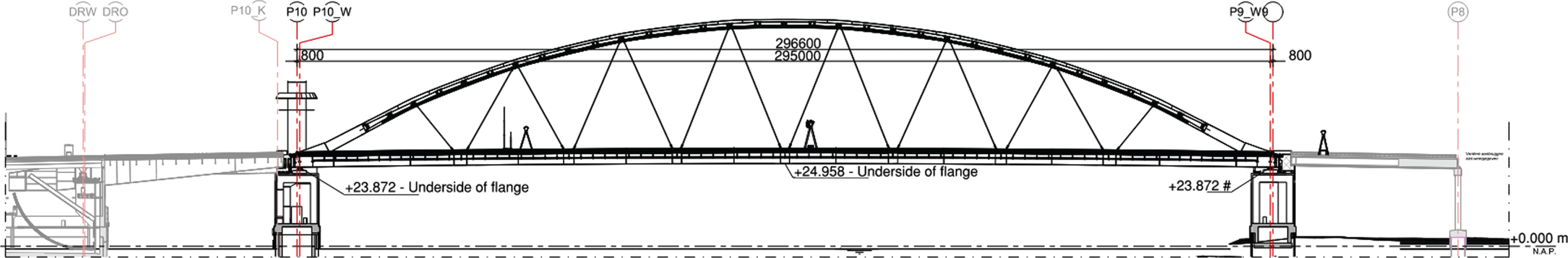
Looking at the project as a whole, the removal of the western bridge became feasible through careful staging of the works, particularly with regards to the replacement of the eastern bridge. The proposed staging is as shown on Fig. 3 and consists of the following steps:
– Step 1) Strengthen the existing western bridge for transportation to the works site (the existing western bridge is referred to as WBBb). Also, build a new bridge off-site (the new bridge is referred to as WBBn) as replacement to take the place of the western bridge while this is strengthened.
– Step 2) Close out the western roadway and float out the existing western bridge (WBBb). Transport the existing western bridge to the fabrication yard to have the strengthening installed in a reduced stress condition.
– Step 3) Install a new western bridge (the new bridge is referred to as WBBn) and open the roadway to traffic.
– Step 4) Close out the eastern roadway and lift out the older eastern bridge (referred to as OBBb).
– Step 5) Transport the renovated western bridge (now referred to as WBBbO) back to the crossing. and reopen the roadway.
– Step 6) Reopen the eastern roadway and recycle the OBBb.
Fig. 3
Bridge swap process (note that the WBBbO is the renovated WBBb).
In all instances the existing foundations are reused with some modifications and strengthening.
Strengthening and reusing the main steel elements is a fundamentally different idea from recycling, where objects are taken apart or materials are melted down and given an application in another product, which requires a greater energy input.
4Strenthening design
4.1Orthotropic deck
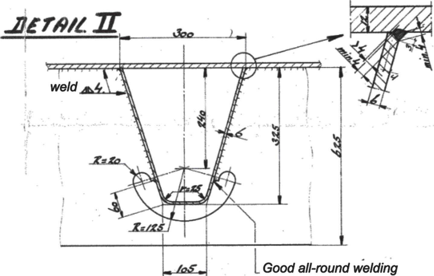
The increase in number of heavy trucks and the use of super single tires (a wider tire favoured on European trucks instead of dual tires) had a detrimental impact on the already fatigue sensitive designed decks. The stress fluctuations at the weld of the trough to the deck plate, at intersection of the troughs with the cross girders, initiated cracks in the deck plate. Damage was predicted in the existing orthotropic deck and inspections confirmed this.
The existing orthotropic deck is shown on Fig. 4 and consist of a 12 mm deck plate with 6 mm troughs. The troughs pass through the cross-girders continuously with a clown’s-mouth detail in the cross-girder comb-plate. The troughs are 325 mm high and 300 mm wide trapezoids spaced at 600 mm.
Fig. 4
Existing orthotropic deck details.
The study of the existing Van Brienenoord Bridge deck and those of other Dutch bridges lead to an extensive research program between the Netherlands Organization for Applied Scientific Research (TNO), Delft University of Technology (TU-Delft), RWS & Arup. The outcome of the research were new rules for the design and analysis of orthotropic decks as part of ROK2.0 [11] and a concept specification for the Eurocode (prTS 1993-1-901 [9].
An improved version of the existing orthotropic deck with trapezoidal troughs was selected, as shown on Figs. 5 and 6. This deck was designed using the new rules stated in ROK2.0 [11], where the stress extraction from FE models is prescribed in combination with new fatigue detail classes.
Fig. 5
Proposed new orthotropic deck.
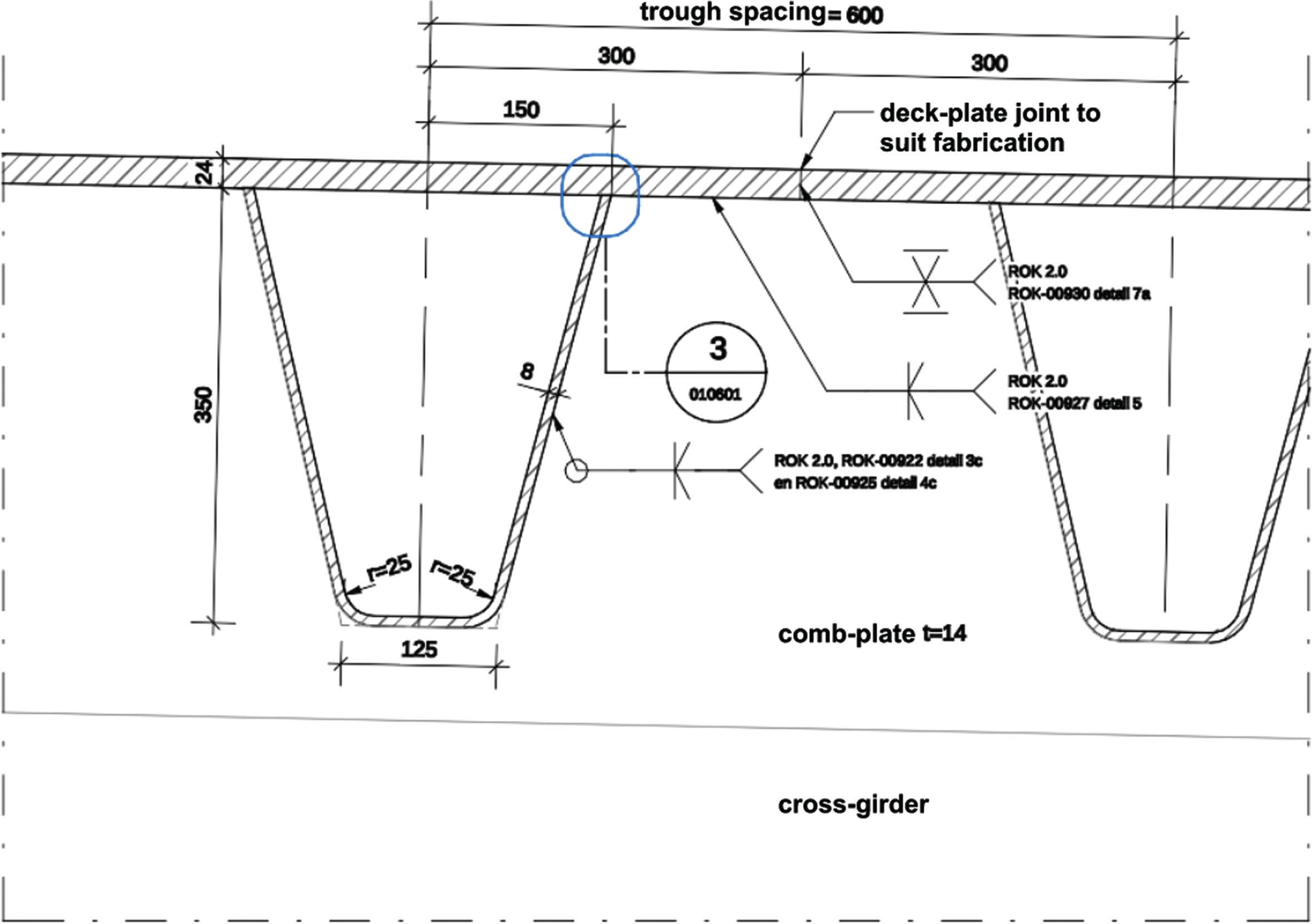
Fig. 6
New orthotropic deck weld details.
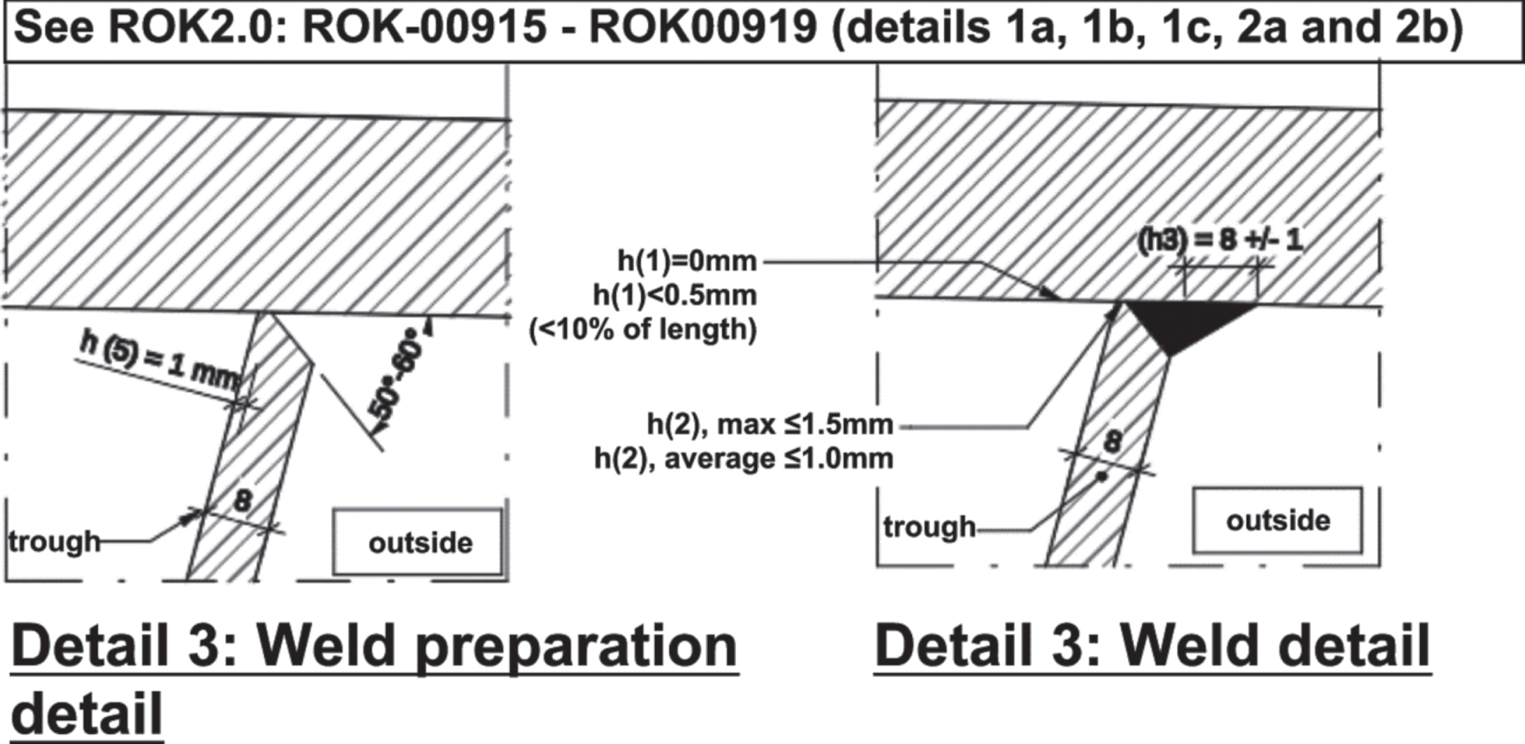
The proposed deck consists of a 24 mm deck plate with 8 mm troughs that run continuously through the cross-girders. The trough spacing is 600 mm with the troughs being 300 mm wide at their top. The increase of plate thicknesses is found necessary to achieve a design life of 100 years using the new design rules.
4.2Arch strengthening
The arch requires strengthening to ensure its structural capacity to the latest design rules and the increased loading on the bridge.
4.2.1Thrust line recentering
The deck is continuously attached to the main girders from end to end of the bridge and thus work together as a single structure in the axial and bending response. Modifying the deck stiffness modified the inertial properties of the Arch Springing Point (ASP) and the effective intersection of the forces between arch and main girder/deck through a shift in the neutral axis. This shift in the NA induced a movement of the thrust line (path of the resultant thrust force) from the arch into the bearings increasing the bending in the arch and main girder. The solution to this was to reposition the bearings closer in, reducing the bridge span. This is shown in Figs. 7 and 8 below.
Fig. 7
Bearing eccentricity due to new deck. Top diagram represents the bending moment due to bearing eccentricity. Bottom diagrams represent resulting thrust/tension lines for the original situation, the increased eccentricity of the strengthened situation with bearings at the original position and the reduction in eccentricity through repositioning of the bearings.
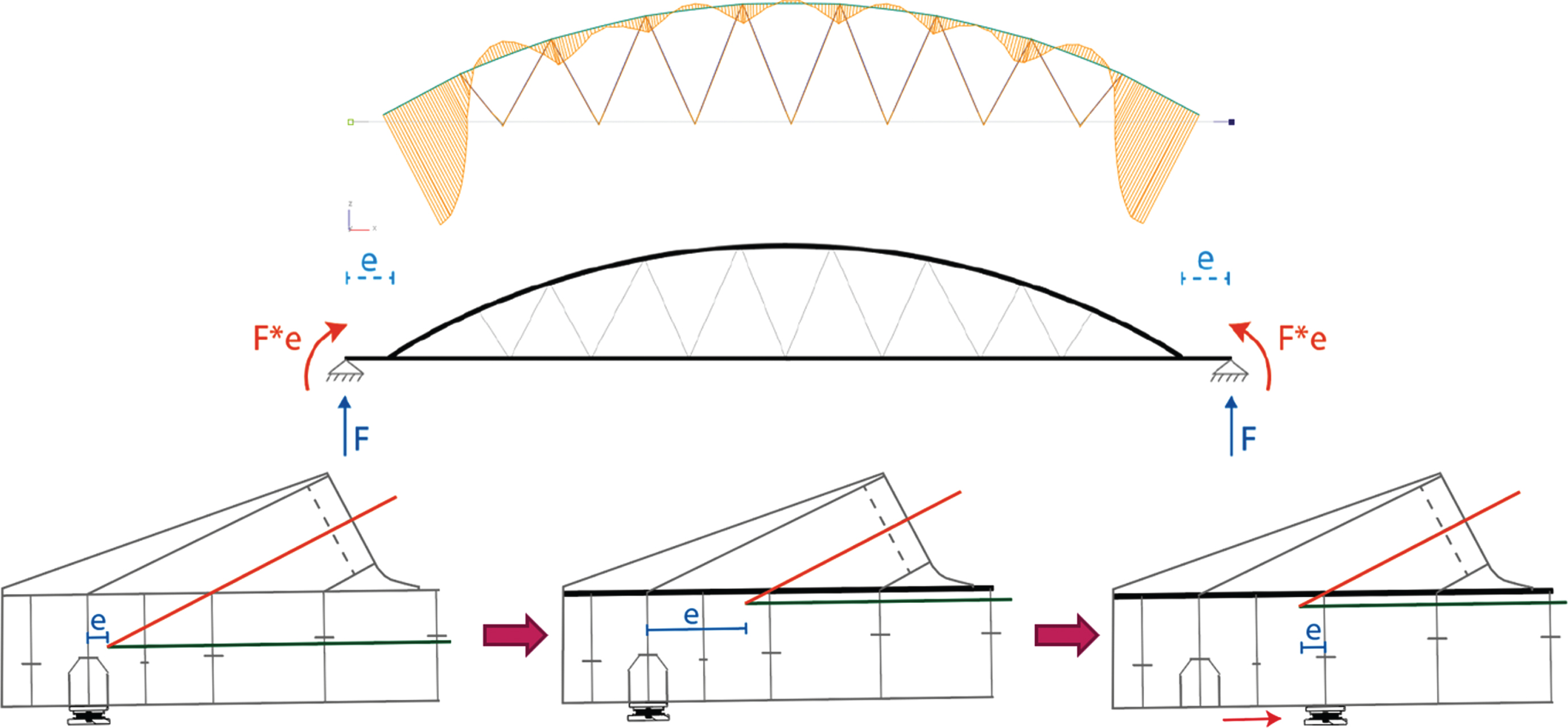
Fig. 8
Bending moment envelopes, due to increased eccentricity (left) and after repositioning the bearings to reduce the eccentricity (right).
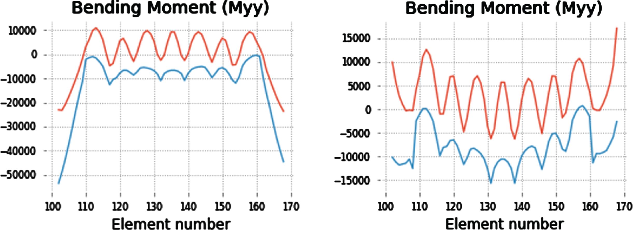
The reductions in bending moments helped in preserving the existing bolted splice of the arch springing to the main girder. However, despite this adjustment, the arch sections still exceeded the yield limit based on gross section stresses throughout the entire length of both arches.
4.2.2Increasing area and stiffness
In the previous section it was concluded that the arch requires strengthening over its complete length. Added cross sectional area and increased stiffness are necessary.
Various strengthening options were considered for the arch. The ones that involved plates on the inside were ruled out immediately due to safety and constructability concerns, given the limited confined space and numerous transverse stiffeners within the box. Flange plates on the outside were also deemed unfavourable because of the arch’s varying radii and multiple kinks being present. The webs, which are in a single plane, were found to be better suited.
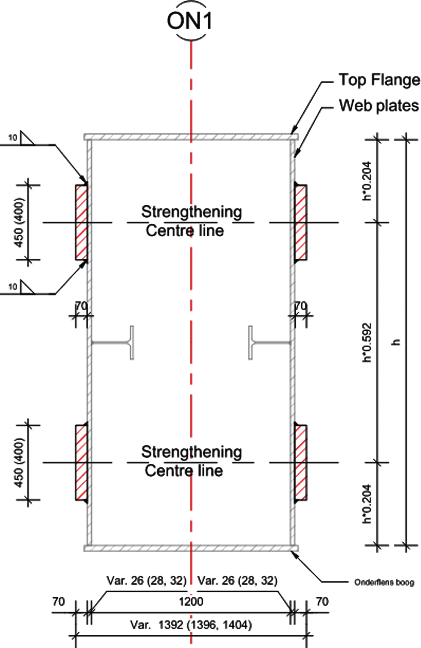
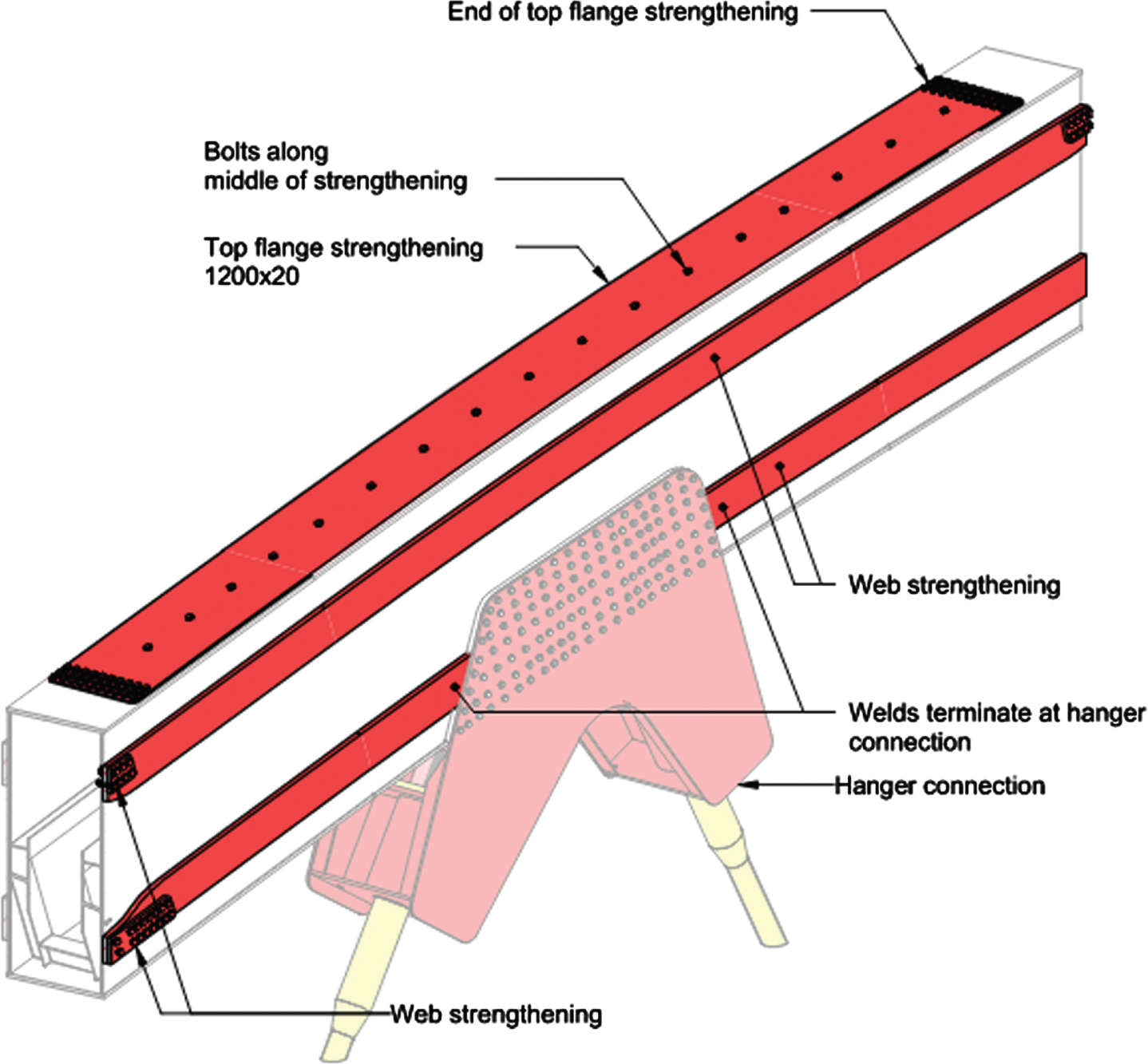
The proposed strengthening consists of four steel strips of 400 or 450 mm x 70 mm attached to the arch webs along the full length, as shown in red on Figs. 9 and 10. This strengthening limits the work within confined spaces to the bolting and minor painting at joints and has relatively simple geometry for forming.
Fig. 9
Arch web strengthening orthographic view.
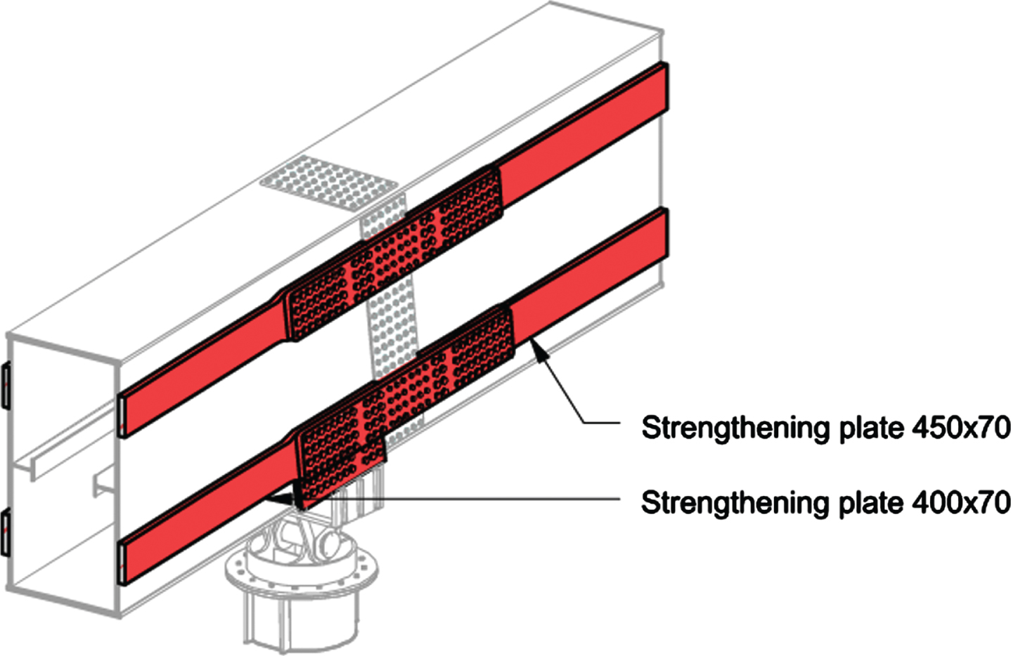
Fig. 10
Arch web strengthening cross-section. Depth (h) varies between 3320 and 2450 mm.
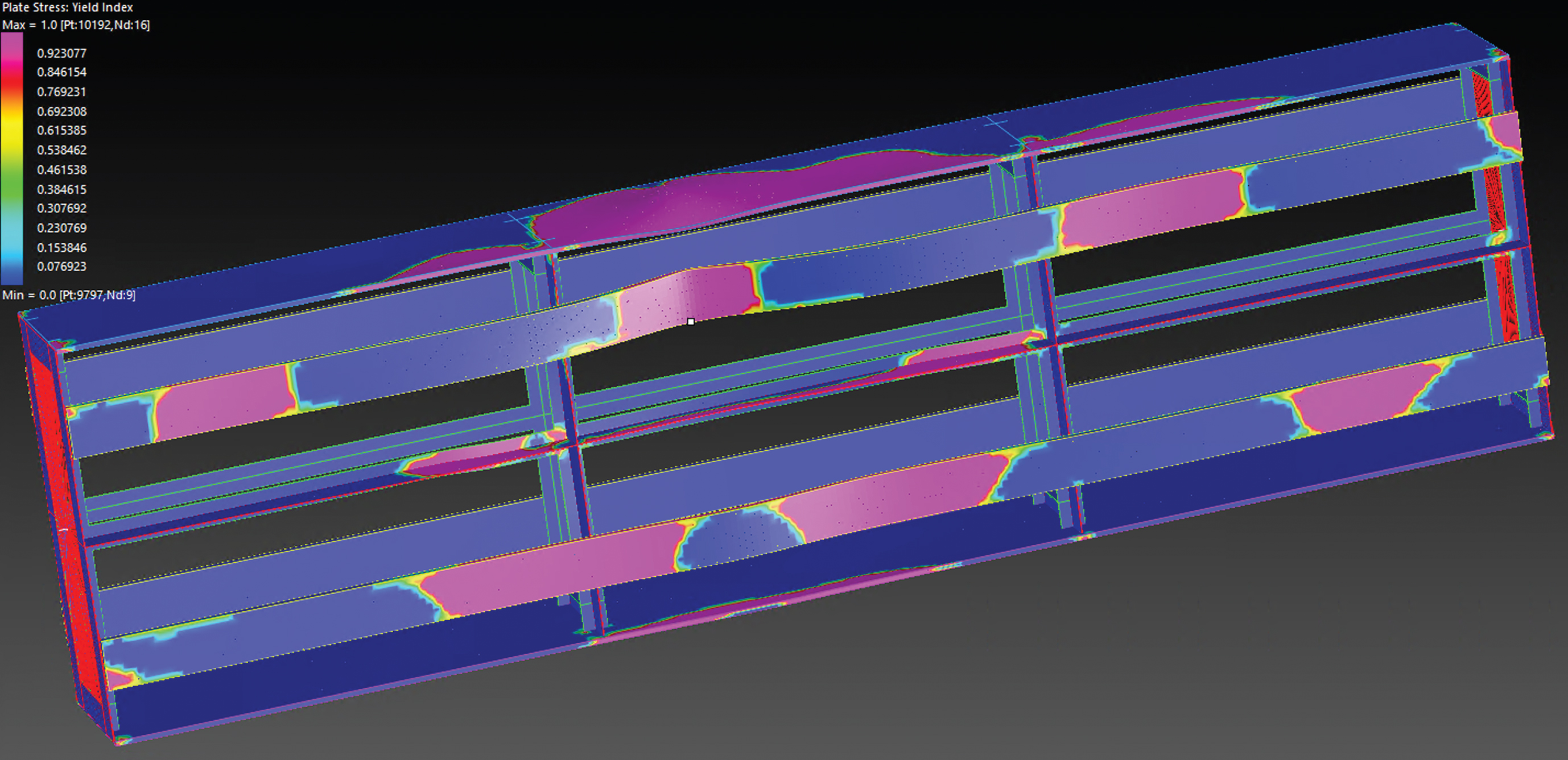
The strips are classified as ‘weak’ stiffeners per the latest draft of Eurocode 3 part 5 [12]. Although not as effective as stiffeners with outstands, strips provide some degree of web plate stiffening to minimize plate buckling. This was found through applying the theoretical rules in the current Eurocode 3 part 5 [13] and was verified by performing a Geometrically and Materially Nonlinear Analysis with Imperfections (GMNIA) using the method described in Eurocode 3 parts 5 [13] and 6 [14]. The results of one GMNIA analysis are shown in Figs. 11 and 12.
Fig. 11
Yield patterns from GMNIA analysis, exterior view. Note: Scale reflects the yield index with blue equals to 0 and fuchsia equals to 1, indicating yielding.
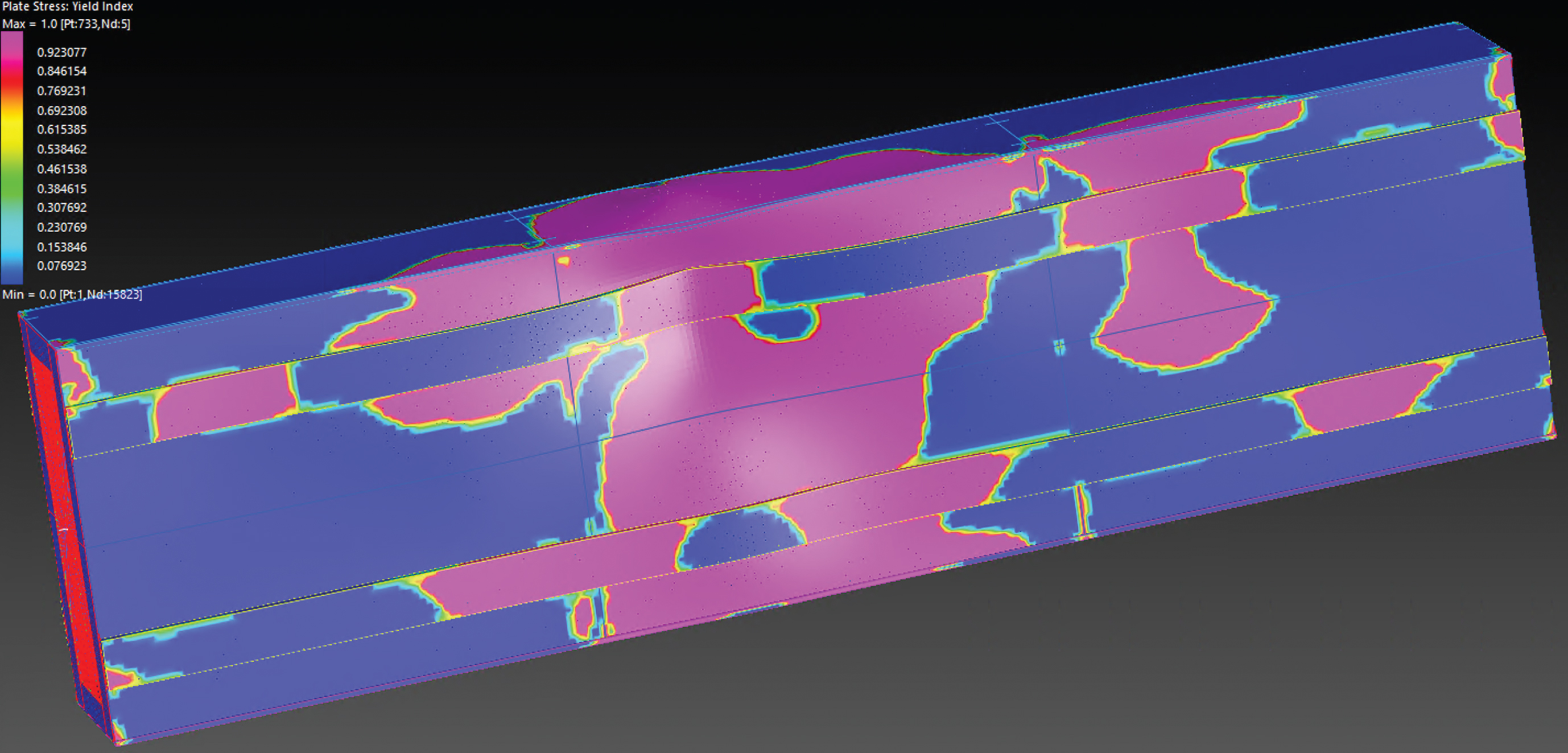
Fig. 12
Yield patterns from GMNIA analysis, view excluding webs. Note: Scale reflects the yield index with blue equals to 0 and fuchsia equals to 1, indicating yielding.
The ends of the plate strengthening are bolted rather than welded for improved fatigue detailing.
4.2.3Flange strengthening at hanger connections
Thin plates are added on the top flange above the hanger connection locations. This creates favorable local eccentricities that counteract the bending moment introduced by tension in the hangers, as illustrated in Fig. 13.
Fig. 13
Eccentric arch strengthening principle.
4.3Main girders
The Main Girders benefit from the increased deck plate thickness and the deck plates of the new cantilevering bikepath and walkway on either side of the bridge. They also benefit from the new bearing location (Section 4.2.1).
The additional loads on the bridge mainly impact the bending on the Main Girders sagging between the hangers. Strengthening plates are added to the bottom flange to increase the capacity in these sections. The extent of these strengthening plates is kept to a minimum by controlling the construction sequence and the stresses locked into the section.
4.3.1Cross girders
Like the main girders the cross girders also benefit from the new thicker deck plate. With this addition all cross girders have sufficient static capacity, except at the arch springing point.
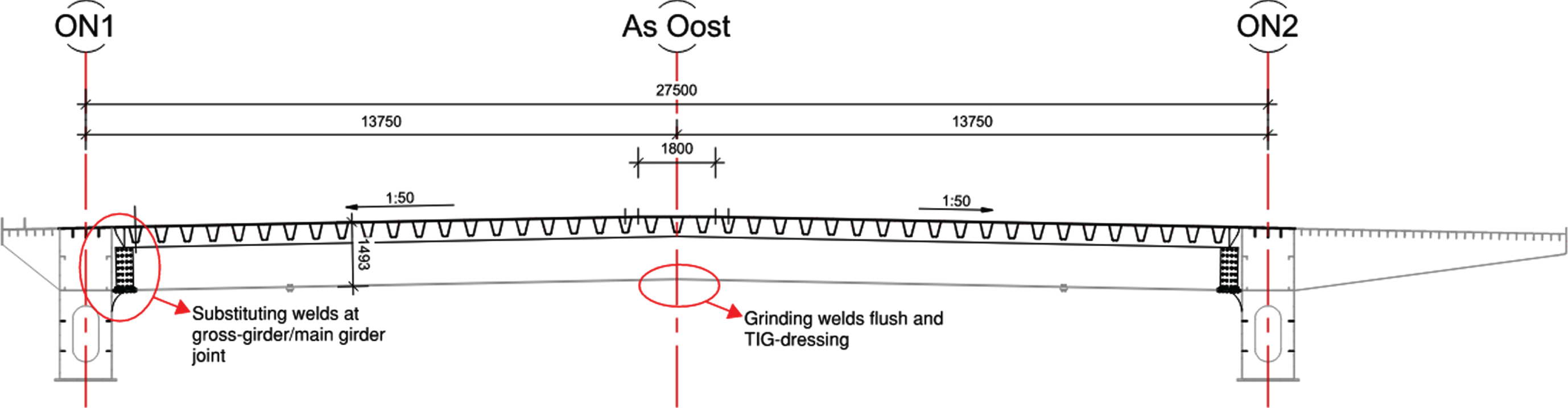
The fatigue assessment of the existing midspan splice were found inadequate for the additional 100-year service life. A solution was found in grinding the bottom flange full penetration welds flush and specifying a weld improvement. Hammer peening was considered as a weld improvement however, the stress ratio (R = smin/smax), which includes permanent SLS stresses, did not meet the requirement; the value was greater than 0.4. Thus, TIG-dressing (post-welding operation consisting in the remelting of the weld toe region aimed to promote a reduction of the stress concentration effect in that zone) was specified in this case as recommended by Hobbacher [15]. TIG-dressing has the added benefit that it resets the historic fatigue damage to zero. Refer to Fig. 14 for the location of the weld improvements.
Fig. 14
Weld improvement on cross girder.
The cross girders are connected to the main girder with a bolted connection for the web and bottom flange, and a full pen weld for the deck plate. Gusset plates are used for the connection, which are welded against the main girder web. The bolted connection itself can be completely re-used, including the splice plates. The existing welds that connect the gusset plates to the main girder are made with double sided 5 mm fillet welds. The diaphragm and horizontal stiffener on the inside of the box girder use the same welds. These details have a low fatigue category, and their assessment gave high fatigue damages. The solution for these connections is to replace the welds with full-penetration welds which increases the weld area and increases the fatigue category. The welding and the resulting connection are susceptible to lamellar tearing and thus the trough thickness properties (z-quality) of the existing main girder webs were tested to determine if they were adequate for the design, which they were found to be, refer to Fig. 14 for the location of the weld improvements.
4.4Hangers & connection
The existing hangers required replacement and increasing in sectional area. The hanger connections within the main girder could not accept an enlargement of the hangers and anchorages without modifications to the steelwork. Thus, various options were studied for replacing the hangers and their connections to the structure.
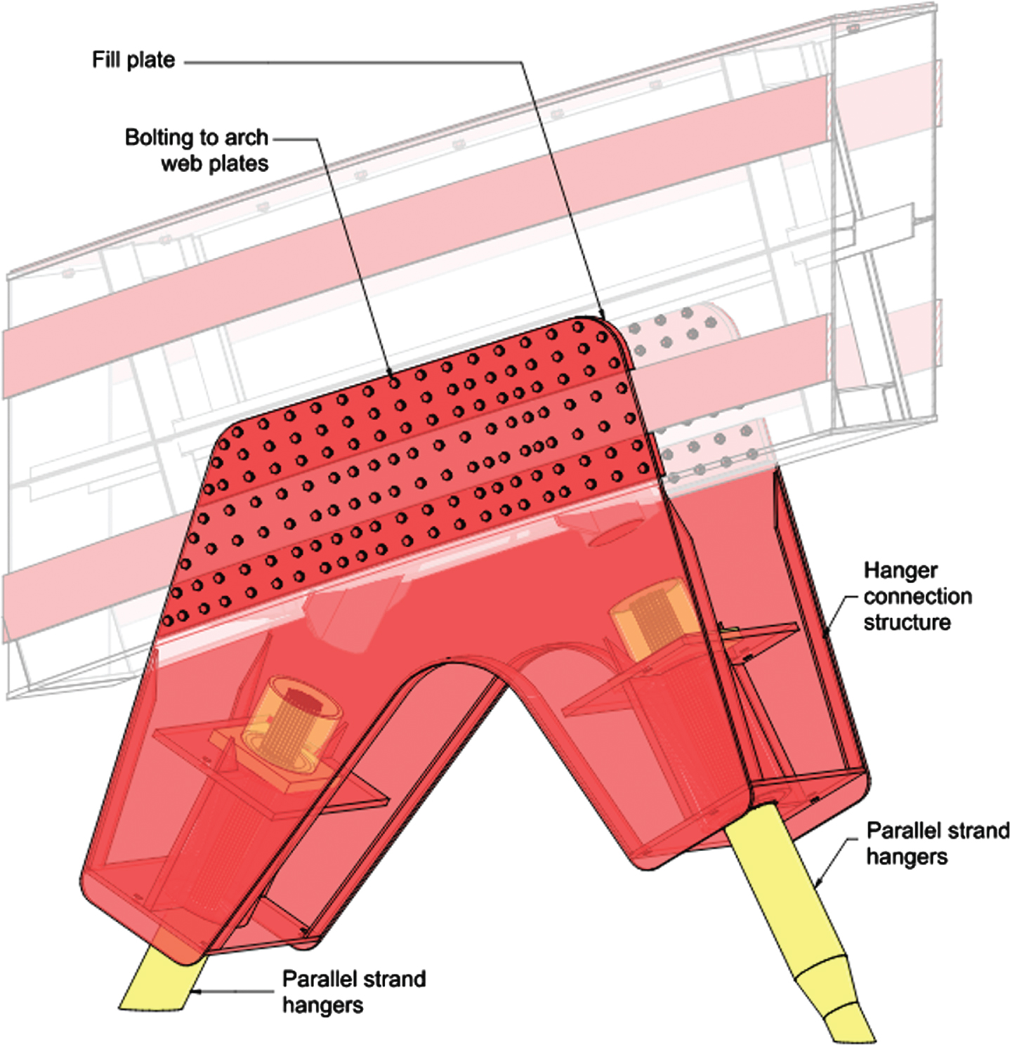
The solution proposed consists of replacing the hangers with a parallel strand system (PSS) and forming the anchorage connections external to the arches and main girders. The PSS has the additional benefit of allowing a strand-by-strand replacement of the hangers with minimal interruptions to the bridge traffic. The existing cable system cannot be replaced with the bridge in service.
The external connections were chosen for multiple reasons:
– they maintain the cable alignment despite the enlarged anchorages;
– they reduce the steel fabrication work within the box girders improving health and safety;
– the arch connection can be formed by bolting straight onto the arch webs, refer to Fig. 15;
– they facilitate cable installation access;
– they allow for inspection and maintenance of the hangers from outside the box girders.
Fig. 15
Hanger-Arch connection typical geometry.
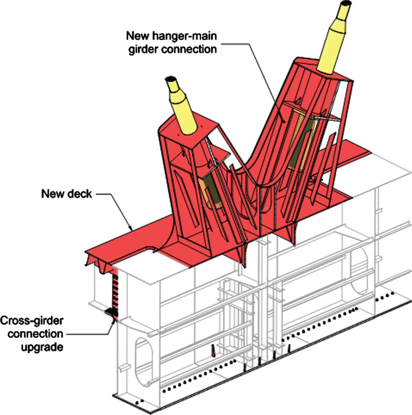
The arrangement of the PSS is for the active end to be at deck level and the passive end at the arch to make stressing easier. The shape of the connection plates has large radii of 600 mm where they intersect the main girder and where opposite hangers intersect. This shape was established to reduce peak stresses. The main girder connection plates cut through the top flange to provide a continuous load path to the girder webs, to which they are connected with full penetration butt welds as shown on Fig. 16.
Fig. 16
Hanger-Main Girder connection typical geometry.
4.5Strengthening construction staging
The main construction staging has been described in the replacement approach in Section 3. The specific process of strengthening the bridge has a great impact on the design, strength and geometry of the bridge through the locking-in or release of stresses and thus is described here in greater detail. The strengthening construction staging was developed with the following objectives:
– Preserve the current roadway vertical alignment.
– Increase certainty of final geometry.
– Reduce locked-in stresses to make the strengthening plates more effective.
The renovated structure was modelled in a detailed global FE model with full staging. The following steps were modelled:
– Replication of the original construction staging based on the as-built information. This is important as it establishes the existing stress state in the bridge.
– support on temporary intermediate supports of the deck, main girders, and arches. The target of this stage is to specify the number and height of temporary supports to unstress the deck prior to its removal.
– Removal of the deck.
– Lowering the main girder to achieve the desired final geometry. With the future addition of the strengthening and the new deck the bridge will be stiffer. The main girder is deformed to a pre-set geometry to achieve the desired target geometry with the least locked in stress.
– Installation of the deck and strengthening while supporting the deck and arch. This reduces the stresses in the existing structure making the strengthening plates more effective.
– Removal of arch supports and secondary main girder supports and lowering of the main girder intermediate supports. The main girder and deck are lowered to increase the distance between hanger connection points.
– Hanger installation and stressing. The new hangers are sequentially installed with a multiple stage stressing to not overstress the structure and maintaining a minimum hanger tension for anchor wedge bite. Under this staging the primary temporary main girder supports are also gradually removed.
– Floating the bridge into its final position.
– Installation of roadway surfacing and other bridge furniture. The final bridge condition.
By analyzing the staged construction, we have been able to specify the steps to follow during construction along with the jacking and propping of the structure to achieve the main objectives.
The construction of large steel structures can be faced with some variability in the response of the structure, typically stiffer response due to material and fabrication tolerances. The proposed sequence includes hold-points to compare the predicted response and the actual response. One key hold point is between hangers stressing steps, where the force in the hangers can be measured, the weight at the bearings can also be measured and as a result the model may be calibrated and updated to best approximate the measured response. The multiple-stage hanger stressing then allows for update to the hanger forces should these be needed.
5The New Western Arch Bridge
In this paper we have mainly focused on the renovation of the existing Western Arch Bridge (WBBb) which will after renovation become the eastern bridge (WBBbO). The new western bridge (WBBn) is a completely new bridge designed to the latest standards with a design and service life of 100 years.
The shape of the new bridge follows that of the renovated bridge, preserving arch and main girder layout and geometry to form a congruent pair of bridges. Key differences with the WBBbO are the following:
– The steel joints and splices are all welded.
– There is no bikepath cantilevering from the side of the bridge. Small maintenance walkways composed of a removable grillage will be attached to the main girders.
– The cross girders have a horizontal bottom flange thus creating a variable depth to these.
– The bridge must be capable of resisting the loss and replacement of any complete hanger at a time.
– The bridge has been assessed for a fire scenario and a fire protection scheme has been developed.
The resulting new bridge is a structure of 7400 tons of steel. This can be used to compare the benefits of strengthening the existing bridge instead of a complete replacement.
6Circularity and sustainability of the design
Renovating the existing western bridge (WBBbO) has its challenges, however, for a 300 m long arch bridge this has led to the reuse of 3200 tons of steel and 3800 tons of new steel for a total of 7000 tons overall. The new western bridge (WBBn) weighs in at 7400 tons, thus by renovating the existing bridge the project is saving approximately 3600 tons of new steel compared to providing two new bridges.
The inclusion of the existing steel for a further 100-year service life is a considerable saving with regards to embodied carbon. This steel has already been in service for 30 years and is thus expected to provide 130 years of service, while also reducing the amount of new steel in the project.
The challenges of transporting and strengthening an existing structure are numerous, however RWS is committed to the principles of circularity and imposing them on a project of this scale sets an example for the construction industry and the works to come.
The future of the existing eastern bridge (OBBb) is still to be determined. Although it is inadequate for the volume of traffic on the A16 highway, a creative use could be found for it providing it with a whole new life. In the worst of circumstances, the steel would be recycled which although ranking lower on the environmental impact than a complete re-use, the demand for new steel plates exists and sourcing the steel from a recycling is better than from new raw materials.
7Conclusions
The design of the renovation of the Van Brienenoord Bridge has included many challenges. Key challenges have been:
– Developing a replacement staging that minimizes traffic disruptions and allows traffic to flow throughout the construction.
– Designing a new orthotropic deck capable of providing 100 years of service life, particularly for fatigue.
– Combining old elements, designed to older design codes and loading criteria, with new elements and ensuring the resulting product is adequate for an extended 100-year design life.
– Designing strengthening elements that reduce construction risks through considerations for access and constructability.
The resulting innovative strengthening design, however challenging, results in a saving of approximately 3600 tons of new steel compared to a complete replacement of the two bridges, thus promoting aspects of the circular economy in the design of major infrastructure projects.
References
[1] | Leffers J , Moustafa A , Vosrtman C Circular Infrastructure: the road towards a sustainable future. Hoofddorp: Holland Circular Hotspot Foundation; (2022) . |
[2] | Van Dooren F , Gration D , den Blanken S , Nagtegaal G , Ashurst D , Kunst P . Orthotropic Deck Fatigue: Renovation of 8 Bridges in the Netherlands. 13th In. Conference on Structural Faults and Repair; (2010) |
[3] | NEN-EN 1990:2021 Eurocode – Basis of structural and geotechnical design. Delft: NEN / European Committee for Standardization. |
[4] | NEN 8701:2011+A1:2020 Beoordeling van de constructieve veiligheid van een bestaand bouwwerk bij verbouwen en afkeuren – Belastingen (Assessment of existing structures in case of reconstruction and disapproval – Actions). Delft: NEN. |
[5] | RBK 1.1:2013: Richtlijnen Beoordeling Kunstwerken 1.1 (Standard: Guidelines for the Assessment of Structures). Netherlands. Rijkswaterstaat. |
[6] | RBK 1.2:2022: Richtlijnen Beoordeling Kunstwerken 1.2 (Standard: Guidelines for the Assessment of Structures). Netherlands. Rijkswaterstaat. |
[7] | Tjepkema D , Delrue S , de Meijier F , van Dooren F Re-use of a 300m steel arch bridge, IABSE Congress Ghent – Structural Engineering for Future Societal Needs. Zurich: IABSE; (2021) . |
[8] | de Jong FBP Renovation techniques for fatigue cracked orthotropic steel bridge decks, Doctoral thesis. Delft: Delft University of Technology; (2007) . |
[9] | prTS 1993-1-901 Eurocode 3 — Design of steel structures — Part 1-901: Fatigue design of orthotropic bridge decks with the hot spot stress method – DRAFT. Delft: NEN / European Committee for Standardization. |
[10] | prEN 1993-1-9:2023 Eurocode 3: Design of steel structures – Part 1-9: Fatigue – DRAFT. Delft: NEN / European Committee for Standardization. |
[11] | ROK 2.0:2021: RTD Richtlijnen Ontwerp Kunstwerken 2.0 (Standard: Engineering Design Guidelines) Netherlands. Rijkswaterstaat. |
[12] | prEN 1993-1-5:2022 Eurocode 3: Design of steel structures – Part 1-5: Plated structural elements– DRAFT. Delft: NEN / European Committee for Standardization. |
[13] | NEN-EN 1993-1-5:2006 Eurocode 3: Design of steel structures – Part 1-5: Plated structural elements Delft: NEN / European Committee for Standardization. |
[14] | NEN-EN 1993-1-6:2007: Eurocode 3: Design of steel structures – Part 1-6: General – Strength and Stability of Shell Structures. Delft: NEN / European Committee for Standardization. |
[15] | Hobbacher A Recommendations for Fatigue Design of Welded Joints and Components, IIW document IIW-2259-15 ex XIII-2460-13/XV-1440-13. Cham: Springer; (2009) . |