
Numerical modelling of an orthopedic brace with increased functional characteristics for the treatment of idiopathic scoliosis
Abstract
BACKGROUND:
Orthotic braces play a key role in the correction of spinal deformities. The effectiveness of these devices depends on the design and distribution of corrective forces transmitted through the corset shell.
OBJECTIVE:
The present study aimed to reduce the weight of the orthosis and improve its functionality while maintaining its corrective function.
METHODS:
The distribution of corrective forces transmitted by the orthosis was evaluated using the finite element method (FEM). Areas of the orthosis, which had minimal impact on the overall stiffness, were identified and material from these areas was removed. The modified orthosis shell was subjected to minor adjustments to maintain its corrective stiffness.
RESULTS:
With the modifications made, a 39% reduction in the weight of the orthosis was achieved, while maintaining its corrective stiffness. This indicates that the corrective function was largely preserved.
CONCLUSION:
The study provides a novel approach to orthosis design demonstrating that optimizing the structure using the distribution of maximum principal stress trajectories can significantly improve the functionality of the brace. The proposed method offers potential advances in the design of various types of orthoses, contributing to developments in the field.
1.Introduction
Idiopathic scoliosis is a three-plane structural deformity of the spine and trunk that occurs in 1–3% of children, most often between the ages of 10–16. Treatment for patients with idiopathic scoliosis with a Cobb angle of 20–40 degrees and skeletal immaturity involves a custom-designed and tailored corrective brace, used simultaneously with specific physiotherapy [1]. The brace is a torso orthosis (corset) made of thermoplastic material. The purpose of bracing is to stop the progression of the spine curvature and to shape the symmetry of the thorax and trunk. The brace is usually worn until bone maturity is complete [2].
A typical Boston or Cheneau brace for the treatment of idiopathic scoliosis has an outer shell that covers a significant portion of the torso to the extent corresponding to the variant of scoliosis for which it was designed. The corset shell is usually made of polypropylene about 4 mm thick and takes the form of a solid structure geometrically adapted to the shape of the patient’s torso. The torso is surrounded by a resilient shell, which has sparse openings to control the pressure exerted by the corrective pads on the trunk. The pads are placed inside the brace at locations corresponding to the vertices of the curvatures of the deformed and rotated spine. Due to this nature of the design of a typical brace, it is not easy to identify the areas of the corset shell responsible for performing the corrective function, i.e. ensuring that the resiliently deformed shell structure, tensioned by means of stretched and locked straps, can transfer significant loads to the pads. The topics of the present work are related to the issues described in the previous publication [3] and represent the next stage of research into defining the working scheme of a Boston brace shell with documented therapeutic efficacy and using the results of this research to enhance its functional properties.
The design of the orthosis greatly affects its functional properties. The characteristics of the brace related to heat and gas transfer at the interface between the body and the corset, as well as the weight of the orthosis, tend to negatively affect patient compliance and quality of life [4]. The challenge is to reduce the weight of the orthosis without compromising its functionality and corrective goals. To address this, advanced analysis of the mechanical structure of the orthosis is required. Optimization of the brace design is needed to reduce the amount of structural material while maintaining corrective stiffness. This requires a detailed understanding of how corrective forces flow through the brace shell.
Finite element modeling (FEM) allows detailed stress analysis, but few studies have thoroughly validated simulations with experimental data [5, 6]. Grycuk and Mrozek recently presented a FEM model of the Boston brace verified experimentally using electronic speckle pattern interferometry (ESPI) [3]. The ESPI system measured the surface displacements of the orthosis in a 3-point loading scheme representing corrective forces. The relative differences between the experimental and FEM displacements were very small, indicating that the FEM model accurately simulated the mechanics of the brace [7].
This study provides a proposition of a brace optimization method based on the results of numerical modeling using a previously verified FEM brace model [3] and an approach based on the idea of force flow lines. As a result, a brace with unchanged corrective stiffness with significantly reduced weight can be developed. This should improve the patient comfort and compliance, thereby improving clinical outcomes. This approach can be adapted to other Thoracic-Lumbar-Sacral Orthosis (TLSO) designs.
2.Materials and methods
2.1Boston brace as a research subject
The Boston brace, designed for non-surgical intervention for scoliosis, is predominantly successful in managing spinal deformities where the apex of the curve lies between the sixth thoracic and third lumbar vertebrae. This type of a brace is uniquely designed to be non-rigid at the top, resting under the patient’s armpits to maintain stability and reduce displacement [2, 8]. In this study, a Boston brace was designed for managing a left lumbar spine curvature. The brace shell was constructed from a 4 mm thick polypropylene sheet, and in this work the authors will focus only on the study of the brace shell.
Unlike complex braces like the Cheneau brace, which uses multiple corrective forces in a spatial system, the Boston brace utilizes a simpler three-point corrective force system [9]. Two forces, A and B, act on the spine by pressuring the ribs, with a third force,
Figure 1.
Diagram of the Boston brace in frontal view-depicting the simplified correction mechanism for the left lumbar curve. Forces exerted by the brace:
The study aims to modify the design of the orthosis to increase its functionality without disturbing the distribution of corrective forces after optimization. This goal requires maintaining the distribution of pressure on the patient’s torso. The model used assumes point loads, although it is known that in real-world scenarios the corrective forces would be distributed over the corrective pads surfaces, while ensuring that the pressure is maintained within a safe range. It should be noted that modeling the pressure of brace on the torso is a complex issue and has been extensively researched [1, 5, 6]. However, in this study, the main goal is to optimize the structure and functionality of the orthosis shell, not to model the pressure of the orthosis on the torso.
2.2Finite element modeling
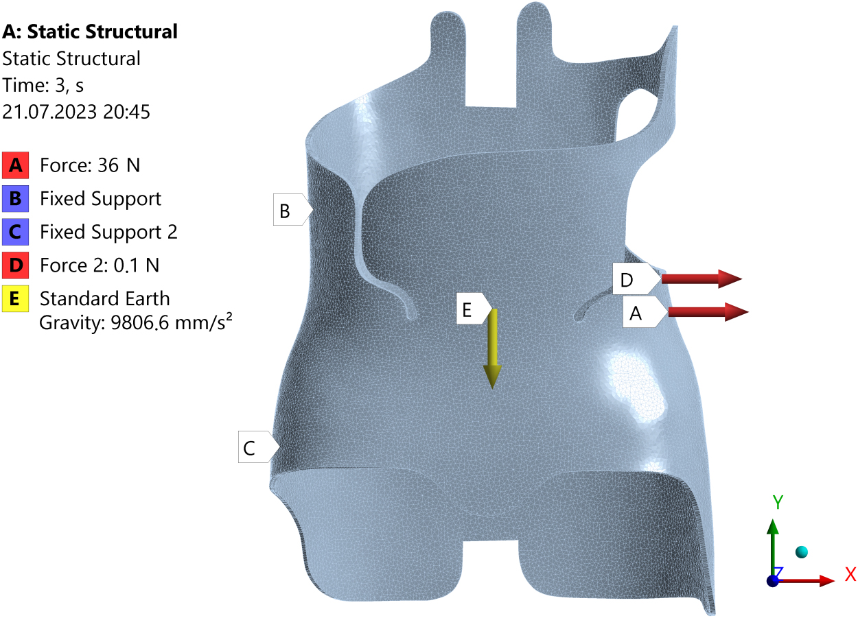
In this study, the parameters of a brace model were set, and a finite element method (FEM) based model was created by generating a FE mesh. In order to be consistent with the conditions used in previous publication [3], this computational model was designed to mimic the experimental tests, applying the same three-point system of forces using supports
Subsequently, an additional force
Polypropylene, commonly used for orthoses, known for its durability and flexibility, was chosen as the shell material of the orthosis. It has a Young’s modulus (
A 10-node tetrahedral element was used to develop the FEM model. This type of element is particularly useful for accurately representing complex geometries in 3D, and its excellent numerical performance in simulating elastic behavior is invaluable for modeling materials such as polypropylene.
An iterative mesh refinement process was applied until the von Mises stress changed by less than 3% with additional node density [13]. The final mesh consisted of 121,253 nodes and 86,187 finite elements with a maximum edge dimension of 10.0 mm.
In addition to the determination of von Mises stresses distribution, the field of principal stresses in the corset shell, represented by a system of vectors assigned graphically for each shell element, was also determined. The relatively dense distribution of principal stress vectors made it possible, in the next step, to plot principal stress trajectories in the most interesting areas of the corset, which were then used to implement structural changes aimed at improving the functional properties of the orthosis.
3.Results
3.1Numerical tests of the original brace
Numerical model was subjected to tests under loads similar to those used in previous FEM studies described by Grycuk and Mrozek [3], specifically a 36 N load applied at point A in line with physiological loading conditions. The results generated a distribution of von Mises stress, as visualized in Fig. 2. Apart from the areas with minimal surface area where the loading force and supports were positioned, most of the orthosis achieved stress levels under 6.9 MPa (Fig. 2). This stress magnitude aligns with the linear portion of polypropylene’s stress-strain relationship [14]. This result substantiated the earlier assumptions about the linearity of the orthosis model.
Figure 2.
View of original brace with equivalent values of von Mises stress.
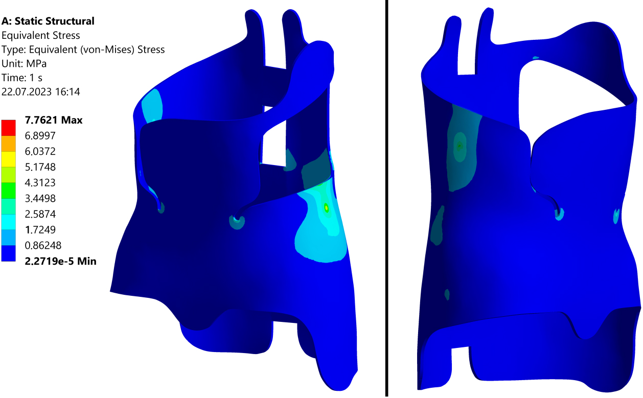
From Fig. 2, it can be seen that the identification of several isolated areas of higher von Mises stresses does not help define the working scheme of the orthosis shell. Much more useful for this purpose is to use the determined distribution of principal stress vectors, and in particular to use this distribution to construct the trajectories of these stresses. Figure 3 provides a representation of the principal stress vectors, specifically for maximum tensile stresses
Figure 3.
Distribution of the principal tensile stress vectors
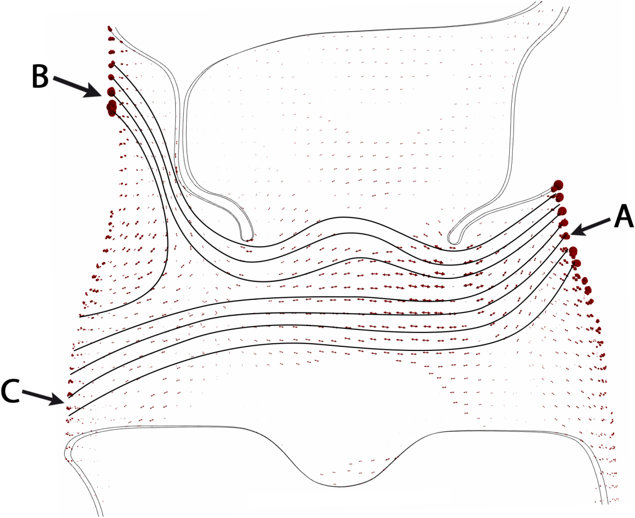
Based on the shapes of the principal stress
Confirmation of this thesis can be obtained, for example, by removing from the original brace structure those parts of the shell where the principal stress trajectories correspond to
3.2Modified brace numerical tests
In order to verify the thesis formulated in Section 3.1, the original geometry of the corset shell was modified. A significant portion of the front wall was removed, leaving only a relatively narrow strip within which the principal stress trajectories corresponded to
Figure 4.
View of modified brace with equivalent values of von Mises stress.
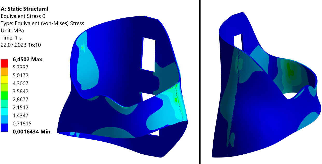
Figure 5.
Distribution of the principal tensile stress vector
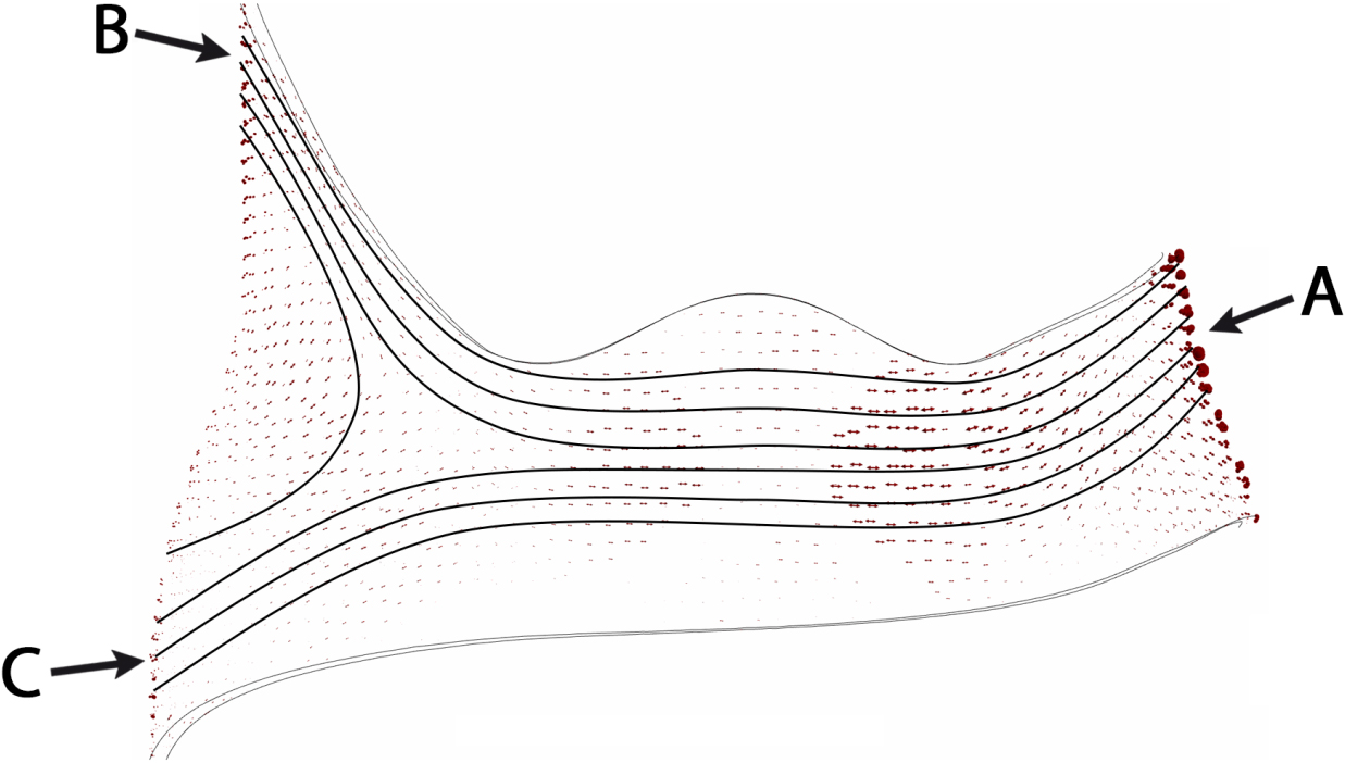
Figure 6.
View of the displacement along the Z-axis of the original and modified brace. The cross-sectional lines A-A, which correspond to the transverse plane, are plotted in the figures. Points
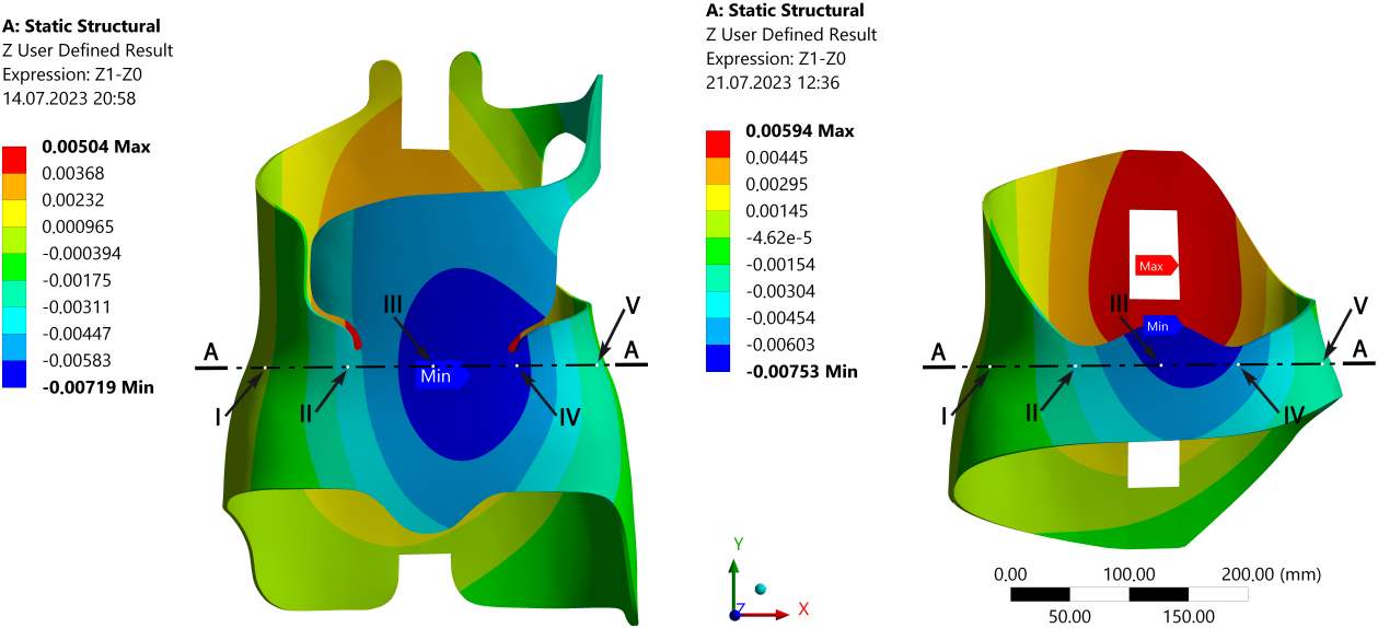
A view of the modified corset shell, including the distribution of von Mises stresses is shown in Fig. 4. The distribution of principal stresses in the front wall of the corset is shown in Fig. 5. It can be seen that despite minor differences, the nature of the distribution of both von Mises stresses and the distribution of principal stresses is very similar for both the original and modified corsets. A similar conclusion can be drawn by comparing the displacement fields of the two corsets after the application of corrective forces, shown in Fig. 6. The results presented suggest that the mechanical characteristics of the two corsets are very similar.
The correction function of a corset is related to its stiffness, which can be further analyzed by determining the brace displacement field occurring in its fixed cross-section in the transverse plane due to applied correction forces. Figure 7 shows a comparison of the displacement fields of the two corsets in the same cross-sections. A comparison of the numerical values of displacements for selected points is shown in Table 1.
Figure 7.
View of 9.6x scaled displacements in cross-section A-A (in the transverse plane marked in Fig. 6) of the braces: gray color – original brace not loaded with corrective forces; red color – original brace loaded with corrective forces; blue color – modified brace loaded with corrective forces.
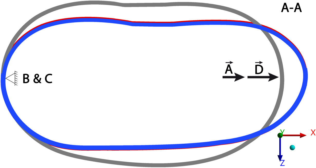
Table 1
Comparison of the displacement of points in the transverse plane (along the Z-axis) shown in Fig. 6
| Point | Displacement in Z direction | Displacement in Z direction |
|---|---|---|
| (original brace) [ | (modified brace) [ | |
| I | ||
| II | ||
| III | ||
| IV | ||
| V |
Based on a comparison of the volume of the original and modified corset, it was calculated that the shell of the modified corset has a mass that is 39% lower than that of the original corset.
4.Discussion
The results of the numerical studies realized in Section 3 showed that it is possible to significantly modify the design of the corset without reducing its corrective properties, resulting from the preserved mechanical characteristics of the shell after proposed modifications.
One of the most important indicators of functionality of an orthopedic brace is its mass. With the minimization of the mass of the orthosis, and therefore with the reduction of the surface area of the shell in the immediate vicinity of the torso, is associated an increase in the values of other functional indicators. Thus, such functional characteristics as the rate of gas exchange at the brace-body interface, the rate of heat exchange across this interface, and the level of psychological comfort of the patient due to the easier discretion of the use of the orthosis, are enhanced. The use of the amount of structural material of the orthosis shell at the level necessary solely for the realization of the corrective function should be the task facing the designer of the orthosis in the first place. A comparison of the weights of the original and modified corset in this study showed that the shell of the modified corset was 39% lighter than the original. The degree of weight reduction could be even higher with a greater degree of modification of the corset back wall design. A possible auxiliary role, such as stabilizing the corset on the torso, played by part of the removed shell can be realized using other solutions that do not require such a large mass of material. Thus, it can be seen that there is great potential for modifying existing typical corset designs based on the results of the research methodology proposed in this work. The degree of weight loss of a modified orthosis in relation to a typical design is therefore an important parameter for determining the potential effectiveness of ongoing research. The direct benefits of the research results may relate to clinical practice, where similar therapeutic results could be obtained, but with the use of much more patient-friendly orthosis.
The numerical analysis presented in this work was carried out on the example of one type of orthopedic corset, which is of course currently a certain limitation. Nevertheless, due to its universality, a similar analysis can be carried out for other types of corsets, e.g. Rigo-Cheneau, looking for similarly favorable results. Although the presented results refer to FEM numerical calculations, it can be concluded that they are highly reliable based on the results of experimental verification of numerical calculations presented in the authors’ earlier work [3].
5.Conclusions
Numerically simulated stress distributions inside the orthosis shell allowed to determine the trajectories of principal stresses to illustrate the flow of forces in the basic three-point pressure system orthopedic brace. As a result, areas of the shell that are particularly important in terms of correction were found and the brace could be modified without the change of its mechanical characteristics. With the modifications made, a great reduction in the weight of the orthosis was achieved, while maintaining its corrective stiffness. The study provides a novel approach to orthosis design demonstrating that optimizing the structure using the distribution of maximum principal stress trajectories can significantly improve the functionality of the brace. The proposed method offers potential advances in the design of various types of orthoses, contributing to developments in the field.
Acknowledgments
The authors have no acknowledgements.
Conflict of interest
The authors declare no conflict of interest.
Funding
The research was carried out within the framework of work no. WI/WM-IIB/2/2023 at Bialystok University of Technology and financed by a research subvention provided by the minister responsible for science. The funders had no role in the design of the study; in the collection, analyses, or interpretation of data; in the writing of the manuscript, or in the decision to publish the results.
References
[1] | Cobetto N, Aubin CE, Parent S, et al. Effectiveness of braces designed using computer-aided design and manufacturing (CAD/CAM) and finite element simulation compared to CAD/CAM only for the conservative treatment of adolescent idiopathic scoliosis: A prospective randomized controlled trial. Eur Spine J. (2016) ; 25: : 3056-3064. |
[2] | Sanz-Pena I, Arachchi S, Halwala-Vithanage D, et al. Characterising the mould rectification process for designing scoliosis braces: Towards automated digital design of 3D-printed braces. Applied Sciences. (2021) ; 11: : 1-13. |
[3] | Grycuk S, Mrozek P. Scoliosis brace finite element model and preliminary experimental testing using electronic speckle pattern interferometry. Applied Sciences. (2022) ; 12: : 1-16. |
[4] | Ng KJ, Duke K, Lou E. Investigation of future 3D printed brace design parameters: Evaluation of mechanical properties and prototype outcomes. Journal of 3D Printing in Medicine. (2019) ; 3: : 171-184. |
[5] | Liao Y-C, Feng C-K, Tsai M-W, et al. Shape Modification of the Boston Brace Using a Finite-Element Method With Topology Optimization: Spine. (2007) ; 32: : 3014-3019. |
[6] | Weiss H-R, Kleban A. Development of CAD/CAM based brace models for the treatment of patients with scoliosis-classification based approach versus finite element modelling. Asian Spine J. (2015) ; 9: : 661-668. |
[7] | Grycuk S, Mrozek P. Numerical and experimental analysis of orthopedic brace for treatment of idiopathic scoliosis. In: Pauk J, Dardzińska-Głébocka A, Mrozek P, et al., editors. Advances in biomedical engineering. Białystok: Oficyna Wydawnicza Politechniki Białostockiej. (2022) ; pp. 15-30. |
[8] | Chung CL, Kelly DM, Steele JR, et al. A mechanical analog thoracolumbar spine model for the evaluation of scoliosis bracing technology. Journal of Rehabilitation and Assistive Technologies Engineering. (2018) ; 5: : 1-9. |
[9] | Rigo M, Jelačić M. Brace technology thematic series: The 3D Rigo Chêneau-type brace. Scoliosis. (2017) ; 12: : 1-46. |
[10] | Clin J, Aubin C-É, Parent S, et al. Biomechanical modeling of brace treatment of scoliosis: Effects of gravitational loads. Med Biol Eng Comput. (2011) ; 49: : 743-753. |
[11] | Mrozek P. The use of electronic speckle pattern interferometry for evaluation of machine tool static stiffness. Lasers in Engineering. (2019) ; 43: : 81-99. |
[12] | Périé D, Aubin CE, Lacroix M, et al. Biomechanical modelling of orthotic treatment of the scoliotic spine including a detailed representation of the brace-torso interface. Med Biol Eng Comput. (2004) ; 42: : 339-344. |
[13] | Grycuk S, Mrozek P. Numerical Analysis of Scoliosis Brace. In: Hadamus A, Piszczatowski S, Błażkiewicz M, et al., editors. The International Conference of the Polish Society of Biomechanics. Cham, Switzerland: Springer. (2021) ; pp. 44-54. |
[14] | Khlif M, Masmoudi N, Bradai C. Polypropylene tensile test under dynamic loading. (2014) ; 21: : 132-138. |


