
Novel dual-resistor-diode limiter circuit structures for high-voltage reliable ultrasound receiver systems
Abstract
BACKGROUND:
The limiters have been used to protect the ultrasound receivers because of the inherent characteristic of the transducers which are required to use the high voltage excitation to obtain the reasonable echo signal amplitudes.
OBJECTIVE:
Among the variety of the limiters, the performances of discharge voltage degradation from the limiters gradually deteriorate the whole ultrasound systems according to the applied voltages of the ultrasonic transducers. This could cause the ultrasound systems to be unreliable for the long-term operations, resulting in possibly breaking the receiver systems.
METHODS:
Designed limiters were evaluated with insertion loss, total harmonic distortion, and pulse-echo responses with the ultrasound transducer devices.
RESULTS:
Designed new dual-resistor-diode limiters exhibited greater and faster suppression of the pulse width (1.15 V and 6.1
CONCLUSIONS:
Our proposed dual-resistor-diode limiter could be one of the potential candidates for reliable ultrasound receiver system.
1.Introduction
Recently, ultrasound systems are widely used to evaluate the performances such as pulse-echo responses and cell responses [1]. The systems are composed of the transmitter and receiver with transducers [2, 3, 4, 5, 6]. The transducers are one of the core devices [7, 8, 9, 10]. The performance of system mainly depends on the performance of the transducer [11, 12]. High voltage (normally higher than 5V
The resistor-diode limiter which uses a 50
2.Methods
2.1Ultrasound system structure
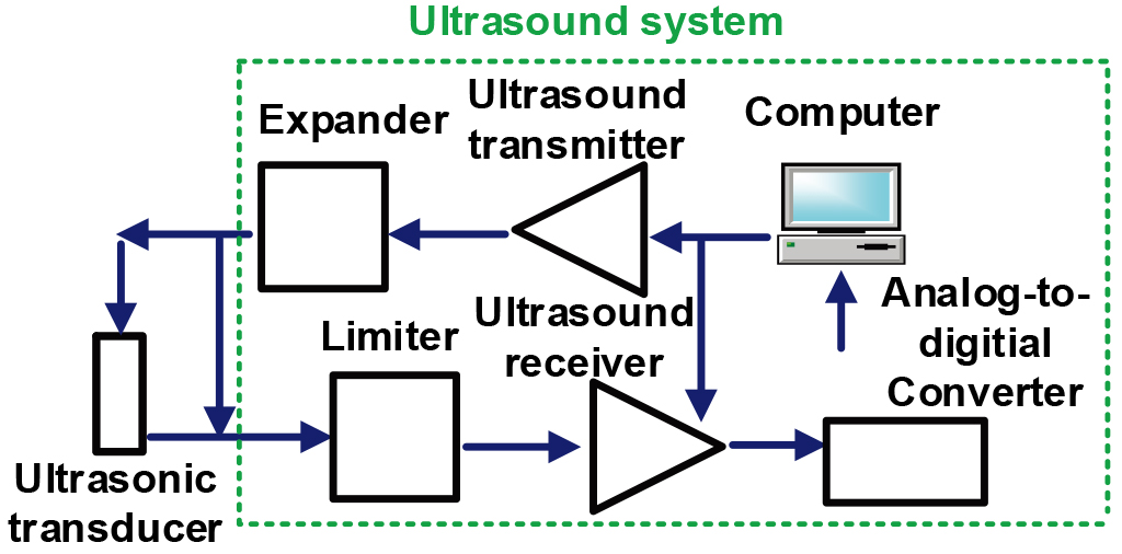
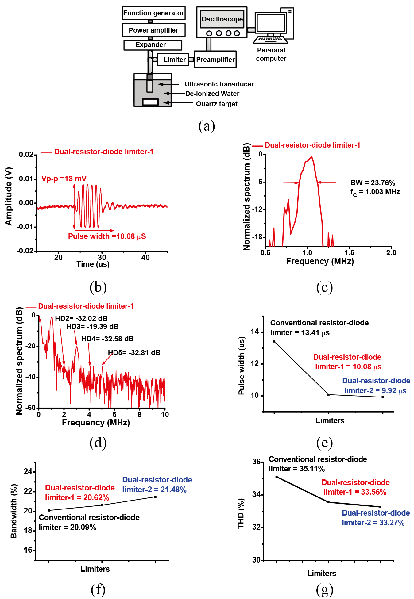
Figure 1 illustrates the block diagram of a typical ultrasound systems with transducers [29, 30, 31]. The transmitter generates single or multi-cycle pulses to trigger the transducers via an expander which is composed of a single diode pairs and the echo signals obtained from the transducers through the limiter are processed by the receivers [32]. However, the receiver is connected and shared by the transducer and transmitter through the expander [14]. Therefore, the limiters need to block the unwanted high voltage signals from the transmitter to protect the receiver. Computer is used to control the excitation pulses and receiving echoes through the transmitter and receiver [33, 34].
Figure 1.
Block diagram of the ultrasound system.
2.2Analysis of the limiters
In the resistor-diode limiter, a resistor with a parallel diode pair is used [35]. In the limiter, the dual-diode is used to increase blocking capability against the high voltage because the high voltage could produce the high echo signals and low discharge voltage. Using the dual-diode can largely improve the reliability. In Fig. 2, the resistors (
Figure 2.
(a) Fabricated limiters; (b) resistor-diode limiter using a 50-

Figure 3.
Equivalent circuit models and operating mechanism of the (a) small signal and (b) large signals: conventional resistor-diode limiter using a 50-
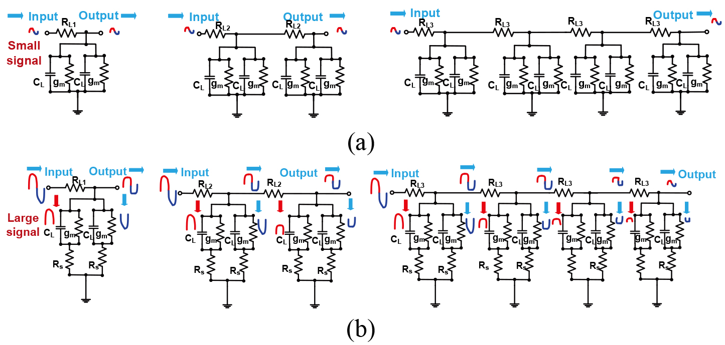
To analyze the mechanism of the small and high voltage signals for each limiter, we derived the small (Fig. 3a) and large signal (Fig. 3b) equivalent circuit models of the limiters [36, 37]. Compared to a single diode pair in the limiter, there are more single diode pairs in the limiter. However, the matching is also important so the impedances in the limiters might be desirable to be 50-
(1)
In Fig. 3b, the high voltage pulse is the input of the limiter. Compared to a single diode pair in the limiter (
3.Results and discussion
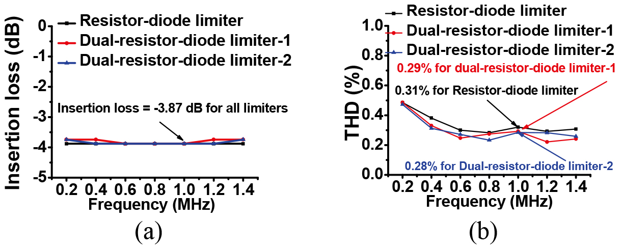
Figure 4 shows the IL vs. frequency of the limiters. Using Eq. (2), IL was calculated from the outputs with and without limiters [45]. Compared to the resistor-diode limiter, the dual-resistor-diode limiters also have same IL (
(2)
Figure 4.
(a) The IL of the resistor-diode limiters and dual-resistor-diode limiters vs. frequency. (b) The THD of the resistor-diode limiters and dual-resistor-diode limiters vs. frequency.
where
Figure 5.
(a) The original signal and (b) suppressed pulses of the resistor-diode limiters and dual-resistor-diode limiters.
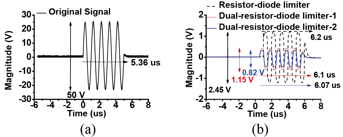
Figure 6.
(a) Pulse-echo measurement setup. (b) Peak-to-peak voltage and (c)
To estimate the distortions, we calculated the total harmonic distortion (THD). Equation (3) shows the equation of the THD of the limiters [40]. Low THD values indicates that the limiters have low signals distortions [36, 46, 47, 48, 49]. Compared to the THD of the resistor-diode limiter (0.31%), the dual-resistor-diode limiters have slightly lower THDs (0.29 and 0.28%)
(3)
where
For high voltage operations, a 5-cycle, 50 V
3.1Pulse-echo measurement
The pulse-echo is typical evaluation method for the ultrasound components such as transducer or transceiver [17, 45]. Thus, we performed the measurement using a transducer (V303, Olympus Corp., Toyko, Japan) in Fig. 6a. Figure 6b shows the magnitude detected by the limiter and receiver. Figure 6c and d show the spectrum of the echo signals. Figure 6e–g show the pulse width, bandwidth and THD. The pulse widths when using proposed limiters (10.08
4.Conclusion
A novel dual-resistor-diode limiter structure to increase reliability for high-voltage receivers is proposed and evaluated in this paper. Compared to resistor-diode limiter, the proposed limiter could further reduce unwanted high voltage discharged signals and shorter pulse widths, thus being more reliable for high-voltage receivers. Because discharge signals provide burden to the reliability of the systems. This proposed limiter is tested in the systems to confirm its capability. In the pulse echo measurement data, when using the proposed limiter, its pulse widths,
Acknowledgments
This work was supported by the National Research Foundation of Korea (NRF) grant funded by the Korean government (MSIT) (No. 2020R1A2C4001606), and supported by the project for Industry-Academic Cooperation Based Platform R&D funded Korea Ministry of SMEs and Startups in 2020 (Project No. S3010583).
Conflict of interest
None to report.
References
[1] | Ullah MN, Park Y, Kim GB, Kim C, Park C, Choi H, Yeom J-Y. Simultaneous acquisition of ultrasound and gamma signals with a single-channel readout. Sensors. (2021) ; 21: (4): 1048. |
[2] | Shin S-H, Yoo W-S, Choi H. Development of public key cryptographic algorithm using matrix pattern for tele-ultrasound applications. Mathematics. (2019) ; 7: (8): 752. |
[3] | Ullah MN, Park C, Pratiwi E, Kim C, Choi H, Yeom J-Y. A new positron-gamma discriminating phoswich detector based on wavelength discrimination (WLD), Nucl. Instrum. Methods Phys. Res. Sect. A. (2019) ; 946: : 162631. |
[4] | Kim J, Ko J, Choi H, Kim H. Printed circuit board defect detection using deep learning via a skip-connected convolutional autoencoder. Sensors. (2021) ; 21: (15): 4968. |
[5] | Kim J, Kim KS, Choi H. Development of a low-cost six-axis alignment instrument for flexible 2D and 3D ultrasonic probes. Technol. Health Care. (2021) ; 29: (S1): 77–84. |
[6] | Kim K, Choi H. Novel bandwidth expander supported power amplifier for wideband ultrasound transducer devices. Sensors. (2021) ; 21: (7): 2356. |
[7] | Choi H, Choe S-w, Ryu J-M. A macro lens-based optical system design for phototherapeutic instrumentation. Sensors. (2019) ; 19: (24): 5427. |
[8] | Kim K, Choi H. A new approach to power efficiency improvement of ultrasonic transmitters via a dynamic bias technique. Sensors. (2021) ; 21: (8): 2795. |
[9] | You K, Choi H. Wide bandwidth class-s power amplifiers for ultrasonic devices. Sensors. (2020) ; 20: (1): 290. |
[10] | Choi H. Development of negative-group-delay circuit for high-frequency ultrasonic transducer applications. Sens. Actuators, A. (2019) ; 299: : 111616. |
[11] | Choi H, Choe S-w. Therapeutic effect enhancement by dual-bias high-voltage circuit of transmit amplifier for immersion ultrasound transducer applications. Sensors. (2018) ; 18: (12): 4210. |
[12] | Kim J, Kim K, Choe S-H, Choi H. Development of an accurate resonant frequency controlled wire ultrasound surgical instrument. Sensors. (2020) ; 20: (11): 3059. |
[13] | Choi H, Yoon C, Yeom J-Y. A wideband high-voltage power amplifier post-linearizer for medical ultrasound transducers. Appl. Sci. (2017) ; 7: (4): 354. |
[14] | Choe S-w, Choi H. Suppression technique of hela cell proliferation using ultrasonic power amplifiers integrated with a series-diode linearizer. Sensors. (2018) ; 18: (12): 4248. |
[15] | Choi H. Development of a class-c power amplifier with diode expander architecture for point-of-care ultrasound systems. Micromachines. (2019) ; 10: (10): 2019. |
[16] | Hoskins PR, Martin K, Thrush A. Diagnostic Ultrasound: Physics and Equipment: Cambridge, United Kingdom: Cambridge University Press; (2019) . |
[17] | Kim K, Choi H. High-efficiency high-voltage class F amplifier for high-frequency wireless ultrasound systems. PLOS ONE. (2021) ; 16: (3): e0249034. |
[18] | Choi H. Stacked transistor bias circuit of class-b amplifier for portable ultrasound systems. Sensors. (2019) ; 19: (23): 5252. |
[19] | Choi H, Woo PC, Yeom J-Y, Yoon C. Power MOSFET linearizer of a high-voltage power amplifier for high-frequency pulse-echo instrumentation. Sensors. (2017) ; 17: (4): 764. |
[20] | Kim J, You K, Choe S-H, Choi H. Wireless ultrasound surgical system with enhanced power and amplitude performances. Sensors. (2020) ; 20: (15): 4165. |
[21] | Choi H. Class-c linearized amplifier for portable ultrasound instruments. Sensors. (2019) ; 19: (4): 898. |
[22] | Poulsen JK. Low loss wideband protection circuit for high frequency ultrasound. IEEE Ultrason. Symp. Oct. 17–20, (1999) ; 1: : 823–826. |
[23] | Choi H, Choe S-w. Acoustic stimulation by shunt-diode pre-linearizer using very high frequency piezoelectric transducer for cancer therapeutics. Sensors. (2019) ; 19: (2): 357. |
[24] | Choi H, Park C, Kim J, Jung H. Bias-voltage stabilizer for HVHF amplifiers in VHF pulse-echo measurement systems. Sensors. (2017) ; 17: (10): 2425. |
[25] | Choe S-W, Park K, Park C, Ryu J, Choi H. Combinational light emitting diode-high frequency focused ultrasound treatment for HeLa cell. Comput. Assisted Surg. (2017) ; 22: (S1): 79–85. |
[26] | Choi H, Jeong JJ, Kim J. Development of an Estimation Instrument of Acoustic Lens Properties for Medical Ultrasound Transducers, J. Healthcare Eng. (2017) ; Sup1: 7. |
[27] | Choi H. Prelinearized class-b power amplifier for piezoelectric transducers and portable ultrasound systems. Sensors. (2019) ; 19: (2): 287. |
[28] | Zawawi RBA, Abbasi WH, Kim S-H, Choi H, Kim J. Wide-supply-voltage-range CMOS bandgap reference for in vivo wireless power telemetry. Energies. (2020) ; 13: (11): 2986. |
[29] | Jeong JJ, Choi H. An impedance measurement system for piezoelectric array element transducers. Measurement. (2017) ; 97: : 138–144. |
[30] | Choi H, Ryu J-M, Choe S-w. A novel therapeutic instrument using an ultrasound-light-emitting diode with an adjustable telephoto lens for suppression of tumor cell proliferation. Measurement. (2019) ; 147: : 106865. |
[31] | Choi H, Yeom J-Y, Ryu J-M. Development of a multiwavelength visible-range-supported opto-ultrasound instrument using a light-emitting diode and ultrasound transducer. Sensors. (2018) ; 18: (10): 3324. |
[32] | Choi H, Ryu J-M, Yeom J-Y. Development of a double-gauss lens based setup for optoacoustic applications. Sensors. (2017) ; 17: (3): 496. |
[33] | Zawawi RBA, Choi H, Kim J. High-PSRR wide-range supply-independent CMOS voltage reference for retinal prosthetic systems. Electronics. (2020) ; 9: (12): 2028. |
[34] | Ullah M, Pratiwi E, Park J, Lee K, Choi H, Yeom J. Wavelength discrimination (WLD) TOF-PET detector with DOI information. Phys. Med. Biol. (2019) ; 65: (5): 055003. |
[35] | Vogt M, Paul B, Scharenberg S, Scharenberg R, Ermert H. Development of a high frequency ultrasound skin imaging system: Optimization utilizing time domain reflectometry and network analysis. IEEE Ultrason. Symp. Oct. 5–8, (2003) ; 1: : 744–7. |
[36] | Katz A. Linearization: Reducing distortion in power amplifiers. IEEE Microwave Mag. (2001) ; 2: (4): 37–49. |
[37] | Choi H, Shung KK. Novel power MOSFET-based expander for high frequency ultrasound systems. Ultrasonics. (2014) ; 54: (1): 121–130. |
[38] | Lee TH. The Design of CMOS Radio-Frequency Integrated Circuits. Cambridge. UK: Cambridge University Press. (2006) . |
[39] | You K, Kim S-H, Choi H. A class-j power amplifier implementation for ultrasound device applications. Sensors. (2020) ; 20: (8): 2273. |
[40] | Johns DA, Martin K. Analog Integrated Circuit Design. New York, NY, USA: John Wiley & Sons; (2008) . |
[41] | Choi H, Li X, Lau S-T, Hu C, Zhou Q, Shung KK. Development of Integrated Preamplifier for High-Frequency Ultrasonic Transducers and Low-Power Handheld Receiver. IEEE Trans. Ultrason. Ferroelectr. Freq. Control. (2011) ; 58: (12): 2646–8. |
[42] | Kim J, You K, Choi H. Post-voltage-boost circuit-supported single-ended class-b amplifier for piezoelectric transducer applications. Sensors. (2020) ; 20: (18): 5412. |
[43] | Zawawi RBA, Choi H, Kim J. High PSRR wide supply range dual-voltage reference circuit for bio-implantable applications. Electronics. (2021) ; 10: (16): 2024. |
[44] | Kang H, Choi H, Kim J. Ambient light rejection integrated circuit for autonomous adaptation on a sub-retinal prosthetic system. Sensors. (2021) ; 21: (16): 5638. |
[45] | You K, Choi H. Inter-stage output voltage amplitude improvement circuit integrated with class-b transmit voltage amplifier for mobile ultrasound machines. Sensors. (2020) ; 20: (21): 6244. |
[46] | Choi H, Jo J-Y, Ryu J-M. A novel focal length measurement method for center-obstructed omni-directional reflective optical systems. Appl. Sci. (2019) ; 9: (11): 2350. |
[47] | Choi H, Ryu J. Design of wide angle and large aperture optical system with inner focus for compact system camera applications. Appl. Sci. (2019) ; 10: (1): 179. |
[48] | Seo SH, Ryu JM, Choi H. Focus-adjustable head mounted display with off-axis system. Applied Sciences. (2020) ; 10: (21): 7931. |
[49] | Chee S, Ryu J, Choi H. New optical design method of floating type collimator for microscopic camera inspection. Applied Sciences. (2021) ; 11: (13): 6203. |
[50] | Choi H, Yang H-C, Shung KK. Bipolar-power-transistor-based limiter for high frequency ultrasound imaging systems. Ultrasonics. (2014) ; 54: (3): 754–758. |


