
Generalized sidelobe canceler beamforming combined with Eigenspace-Wiener postfilter for medical ultrasound imaging
Abstract
BACKGROUND:
The beamforming algorithm is key to the image quality of the medical ultrasound system. The generalized sidelobe canceler (GSC) beamforming can improve the image quality in lateral resolution, but the contrast is not improved correspondingly.
OBJECTIVE:
In our research, we try to optimize the generalized sidelobe canceler to obtain images that achieve an improvement in both lateral resolution and contrast.
METHODS:
We put forward a new beamforming algorithm which combines the generalized sidelobe canceler and Eigenspace-Wiener postfilter. According to eigenspace decomposition of the covariance matrix of the received data, the components of the Wiener postfilter can be calculated from the signal matrix and the noise matrix. Then, the adaptive weight vector of GSC is further constrained by the Eigenspace-Wiener postfilter, which make the output energy of the receiving array closer to the desired signal than the conventional GSC output.
RESULTS:
We compare the new beamforming algorithm with delay-and-sum (DS) beamforming, synthetic aperture (SA) beamforming, and GSC beamforming using the simulated and experimental data sets. The quantitative results show that our method reduces the FWHM by 85.5%, 80.5%, and 38.9% while improving the CR by 123.6%, 47.7%, 84.4% on basis of DS, SA, and GSC beamforming, respectively.
CONCLUSIONS:
The new beamforming algorithm can obviously improve the imaging quality of medical ultrasound imaging systems in both lateral resolution and contrast.
1.Introduction
Ultrasonic imaging is an important means of medical diagnosis, which has the advantages of strong penetration and little harm [1, 2]. Thereinto, the beamforming algorithms have the decisive influence on the quality of echo images. The most common beamforming algorithm is delay-and-sum (DS) beamforming [3]. It can achieve receiving focus of the beam. On this basis, synthetic aperture (SA) beamforming [4] further realizes the emission focusing. These algorithms can improve the accuracy of medical ultrasonic systems [5]. However, by only achieving beam focus, the main lobe of the beam is still wide and the sidelobe is high, causing a low resolution and contrast of images [6]. Thus, a more efficient beamforming algorithm is necessary for improving the image quality.
The DS and SA belong to the non-adaptive beamforming, and many researchers pay more attention to the adaptive beamforming field recently. In adaptive algorithms, an adaptive weight vector is introduced to process the received signal [7]. Unlike the preset weights in non-adaptive beamforming methods, this weight vector is updated as the received signal changes, ensuring the best performance of interference suppression at each point [8]. Therefore, with the appropriate weights, the adaptive beamforming algorithm can obtain a narrower main lobe and a lower side lobe, so the image quality is improved. In adaptive beamforming research, Capon first put forward the minimum variance beamforming in 1969 [9]. Then the beamforming is deeply studied by researchers. Holfort extended minimum variance method into frequency domain [10]. Synnevåg applied it to medical ultrasonic imaging [11]. Due to the coherence of medical ultrasound signal, the spatial smoothing is proposed by Evans [12]. Moreover, Synnevåg come up with the diagonal loading approach for the robustness [13].
Though the minimum variance method can bring better image quality, it still suffers signal cancellation. Thus, researchers have tried to find an alternative approach [14]. Griffiths proposed generalized sidelobe canceler (GSC) beamforming [15]. It introduces a block matrix to solve the signal cancellation and changes the constraint structure of adaptive beamforming. In addition, Li introduced the GSC beamforming into medical ultrasonic imaging [16]. Previous studies have shown that GSC can effectively improve resolution, but not contrast which is also important for medical image analysis [17]. Therefore, it is necessary to improve the contrast performance of the GSC beamforming while maintaining the advantage of high resolution.
For the medical ultrasound imaging, the main lobe width of the beam determines the lateral resolution of the system, while the sidelobe level has an influence on the contrast. Moreover, the desired signal concentrates on the main lobe, and the noise signal causes the sidelobe. Therefore, the closer the result of beamforming is to the desired signal, the better the image quality is. Recently, the Wiener postfilter beamforming has been widely studied [18, 19], in which the response of Wiener filter is considered as a coefficient of beamforming. The response of the filter should meet the condition that the mean square error between the beam output and the desired signal is minimized [20]. By using this post-weighting factor, the output power of the beamformer will be closer to the desired signal, so a beam with narrower main lobe and lower sidelobe can be achieved. Thus, a better resolution and contrast could be expected. However, to build a Wiener postfilter, the energy of the desired signal and the noise signal must be obtained first, and some methods to estimate the two components have been proposed [21, 22], but they are always complicated and not accurate enough.
In our study, we design a new beamforming algorithm which combines the GSC beamforming and the Wiener postfilter. Benefiting from the characteristics of covariance matrix, it can be easily divided into signal matrix and noise matrix by eigenspace decomposition method. Then the Wiener postfilter can be constructed by the corresponding matrices and the adaptive weight. Some experiments are conducted using simulated data set and real echo data. The results indicate that the new beamforming (GSC-ESW) can achieve significant improvement in contrast as well as lateral resolution.
The rest part of the manuscript is structured as follows: we describe the imaging model of medical ultrasound system, and the principle of GSC beamforming and Wiener postfilter in Section 2. Then we elaborate on the design of GSC-ESW in Section 3. The experimental results are displayed in Section 4. The performance of the new beamformer is discussed in Section 5. Finally, we give the conclusion of our research in Section 6.
2.Background
2.1Synthetic aperture (SA)
Synthetic aperture (SA) beamforming is a widely used non-adaptive beamforming algorithm. It can realize transmitting and receiving focusing of beam [23], which provides a good foundation for the adaptive beamforming. Generally, the SA beamforming is implemented as follow: Firstly, in each scan, only one element is used to emit ultrasonic pulses, and all the array elements receive the echo signal. Moreover, the received data are processed by DS beamforming to realize the receiving focus. Then we repeat the above process on each single transmission element in the array and obtain a series of low-resolution images (LRI). Finally, all the low-resolution images are added and averaged to produce a high-resolution image (HRI), which achieves the transmitting focus.
For a linear transducer array, we assume it consists of M elements, the high-resolution image of SA can be expressed as:
(1)
where
2.2Sensor signal model
Considering a linear transducer array consisting of M elements, the beamformer output is expressed by [27]:
(2)
where
(3)
where
2.3Generalized sidelobe canceler (GSC)
In adaptive beamforming, the weight vector should minimize the interference and noise power while the desired signal can pass without loss. This constraint is formed by [28]:
(4)
where
Figure 1.
Structure of generalized sidelobe canceler.
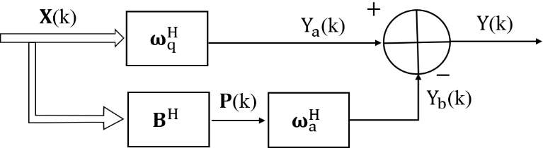
Figure 1 shows the structure of GSC beamforming. It separates weight vector
(5)
Through the operations above, the constraints of Eq. (4) can be redefined as:
(6)
And the answer of Eq. (2.3) is:
(7)
(8)
The blocking matrix
(9)
In practice,
(10)
(11)
(12)
where
2.4Wiener postfilter
In medical ultrasound imaging, the Wiener postfilter is introduced to minimize the mean square error between the total output power of the beamformer and the desired signal power [34]. The response of the filter is calculated by:
(13)
The optimal solution Eq. (13) is
(14)
where
3.Proposed method
To further improve the performance of GSC beamformer, we propose a new beamformer which introduce an Eigenspace-Wiener postfilter to optimize the conventional GSC. And the new beamformer is called GSC-ESW for short. In this approach, the Wiener filter is constructed using the result of the eigenspace decomposition of
3.1Eigenspace decomposition
For the GSC beamforming, the sample covariance matrix
(15)
where
Through the eigenspace decomposition, the sample covariance matrix
(16)
where
3.2Eigenspace-Wiener postfilter
According to Eq. (2) and (16), the beamformer output is given by:
(17)
Equation (17) indicates that the output energy of the beamformer can be calculated by the sample covariance and adaptive weight vector. What is more, the output energy can be further decomposed into signal energy
(18)
3.3GSC with the Eigenspace-Wiener postfilter
To improve the performance of GSC, the adaptive weight is optimized by the Eigenspace-Wiener postfilter. And the new optimized weight can be expressed as:
(19)
With the new adaptive weight, the beamformer output is:
(20)
Comparing the Eqs (17) and (20), the first terms of the two equations are same, which represent the desired signal power, but the second terms are different which represent noise power. Specifically, for the echo signal from the point targets, the desired signal is much bigger than noise signal, so the noise power in Eqs (17) and (20) are all small, but our method can obtain a smaller result. For the region of anechoic lesion, there are few desired signals in the echo and it is full of noise. Since the noise signal power is much bigger than the desired signal power, a quantity of artifacts and noise will occur in the echo images. However, noise power in GSC-ESW is very small because the denominator of the second term of Eq. (20) is much bigger than 1. Therefore, GSC-ESW can make the output closer to the desired signals no matter how the noise signals change. As the noise is further suppressed, the GSC-ESW can achieve better lateral resolution and contrast.
4.Results
In order to verify the effectiveness of the algorithm, simulated experiments and real data experiments are carried out. Then we compare the beamforming responses of GSC-ESW with DS, SA, and GSC beamforming. Relevant indexes are used to evaluate the quality of the algorithms including the full width at half-maximum (FWHM), peak sidelobe level (PSL), and contrast ratio (CR), which can quantitatively describe the performance of the lateral resolution, sidelobe energy, and contrast, respectively.
The simulated data of point targets and cyst target are obtained by Field II [36, 37]. We simulate a linear array with 64 elements. Its central frequency is 3.33 MHZ and the spacing of elements is 0.2413 mm. In addition, sampling rate of the system is 71.4 MHZ, and the sound velocity is 1540 m/s. The real data is provided by the biomedical ultrasonic laboratory, Biomedical Engineering Department, University of Michigan, and its parameters are consistent with those of the simulated data.
Figure 2.
Simulated point targets images with different algorithms. (a) DS; (b) SA; (c) GSC; (d) GSC-ESW. The dynamic range of image is 60 dB.
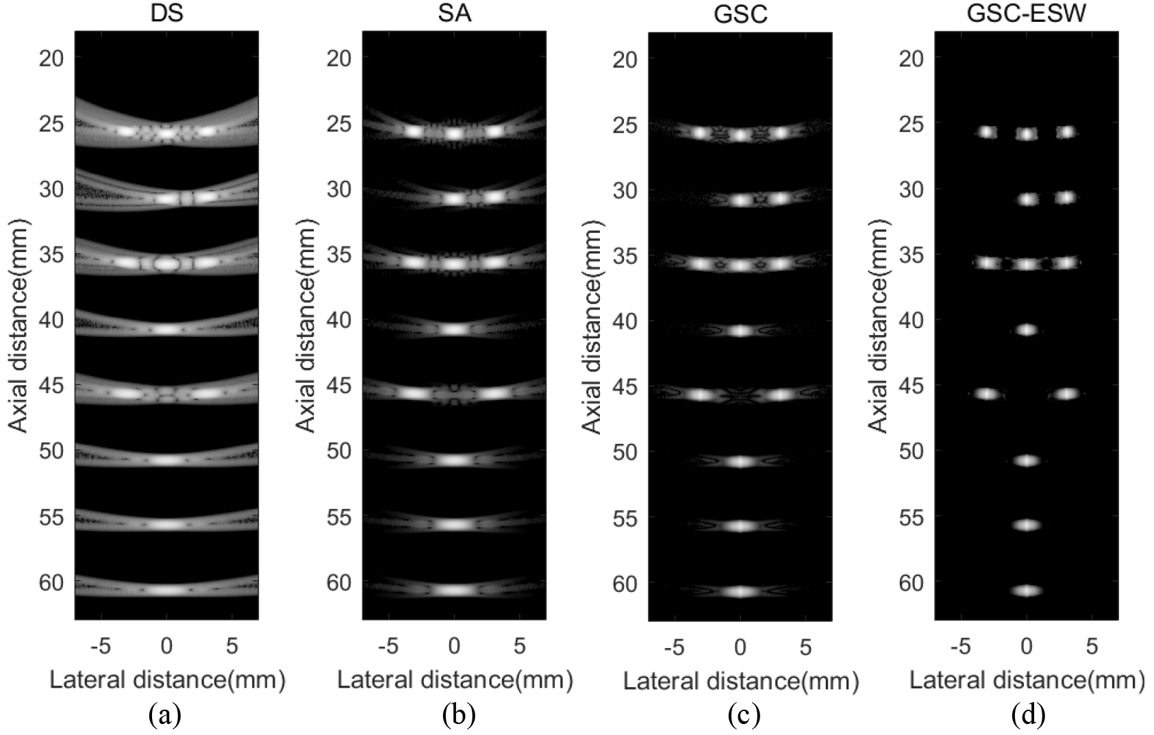
4.1Simulated point targets
In this section, there are several point targets in the detection space, and the simulated data are processed by different algorithms. Figure 2 shows the imaging results. Figure 3 is the lateral variation curve of point targets at the depth of 40 mm and 45 mm. As shown in Fig. 3, GSC-ESW obtains the narrowest main lobe and lowest sidelobe between the four algorithms. Taking
Table 1
FWHM
| Algorithm | FWHM (mm) | PSL (dB) |
|---|---|---|
| DS | 1.52 | |
| SA | 1.13 | |
| GSC | 0.36 | |
| GSC-ESW | 0.22 |
Table 2
Contrast ratio (CR
| Algorithm | Mean intensity in the cyst region (dB) | Mean intensity in the background (dB) | CR (dB) |
|---|---|---|---|
| DS | 25.69 | ||
| SA | 38.90 | ||
| GSC | 31.15 | ||
| GSC-ESW | 57.45 |
Figure 3.
Lateral variation of different algorithms at (a)
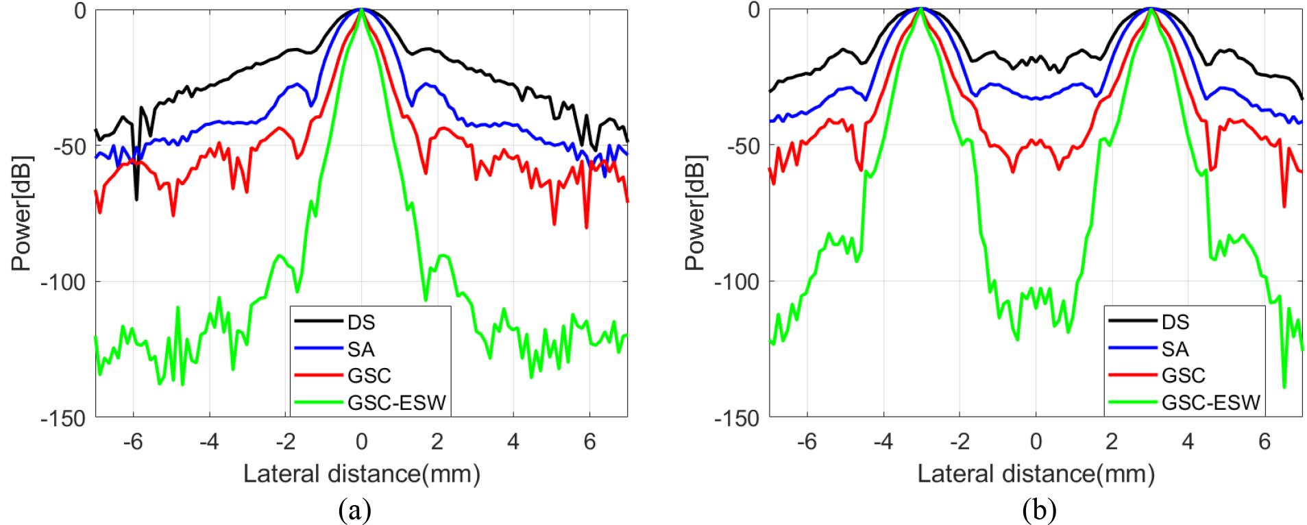
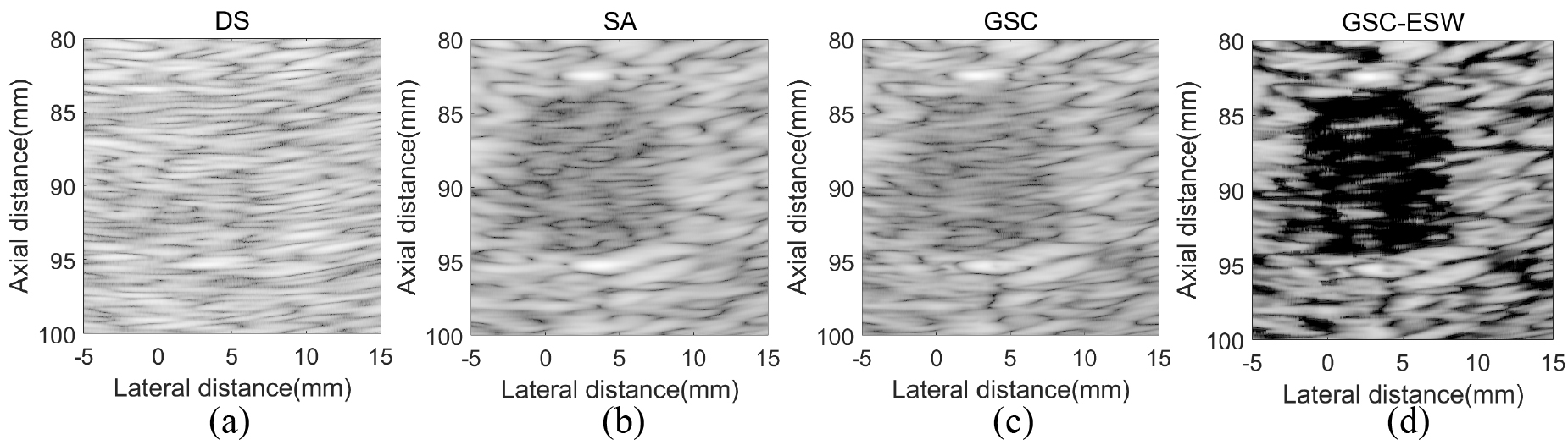
Figure 4.
Simulated circular cyst target images with different algorithms. (a) DS; (b) SA; (c) GSC; (d) GSC-ESW. The dynamic range of image is 60 dB.
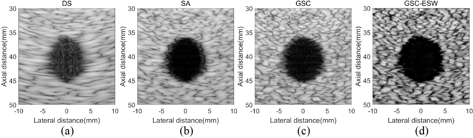
Figure 5.
Lateral variation at
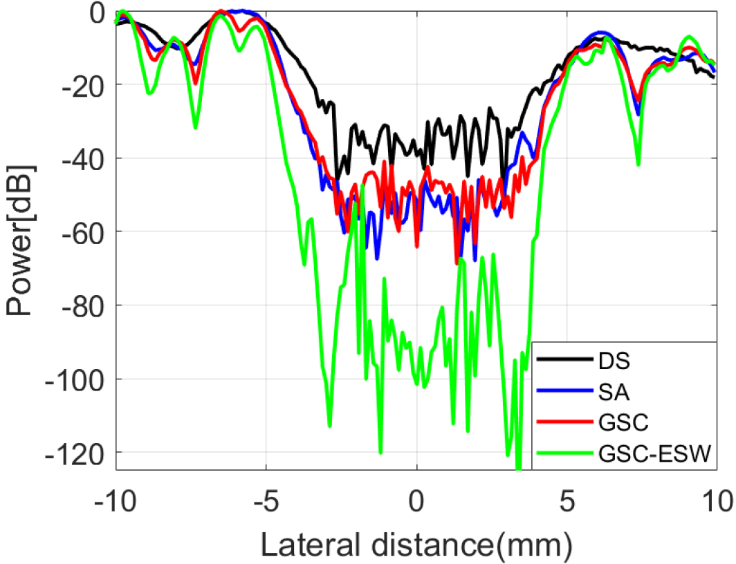
4.2Simulated cyst targets
In this section, the echo data of a circular cyst target in a high speckle noise environment is simulated by Field II. The circular cyst is located at (
Figure 6.
Real data images with different algorithms. (a) DS; (b) SA; (c) GSC; (d) GSC-ESW. The dynamic range of image is 60 dB.
4.3Real echo data experiment
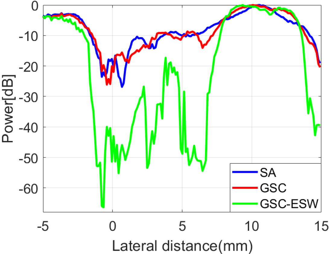
In this section, we use the real echo data to test algorithms. Figure 6 shows the beamforming response of different algorithms. Since the actual system is not as ideal as the simulated environment, more noise and errors will appear in the echo data [38], which make it difficult for beamformers to obtain accurate images. From Fig. 6a, we can see that the cyst is completely drowned out by the noise signal, while GSC-ESW leads to a clearly distinguishable results in Fig. 6d. The SA and GSC are also obviously disturbed by noise in Fig. 6b and c. Since the DS is difficult to distinguish the target, we do not carry out quantitative analysis on it. The lateral variation of SA, GSC, and GSC-ESW is shown in Fig. 7. According to quantitative calculation, the CR of SA, GSC and GSC-ESW are 8.56 dB, 6.25 dB, and 31.27 dB, respectively. This experiment shows that the new beamformer can still perform well in practical application.
Figure 7.
Lateral variation of real data at
5.Discussion
In the present study, we try to use the Wiener postfilter to optimize the GSC beamformer to further improve the quality of images in medical ultrasound imaging. And the eigen structure of covariance matrix provides a good foundation for the application of the Wiener postfilter, which make the construction of Wiener postfilter convenient and accurate. Simulated and experimental results confirm the validity of the new beamforming algorithm.
In point targets experiment, GSC-ESW achieves an obvious improvement over the non-adaptive beamformers DS and SA. GSC-ESW increases the lateral resolution of DS and SA by more than 80%. Compared with the conventional GSC, GSC-ESW also provides a narrower main lobe and lower sidelobe according to Fig. 3. As the desired signal concentrates on the main lobe while the noise signal distributes in sidelobe, GSC-ESW takes 38.9% increase in lateral resolution and 46.89 dB decrease in sidelobe energy, which confirms that output of the new beamformer is closer to the desired signal.
According to cyst target experiment, we find that although the GSC obtains a better the lateral resolution than the non-adaptive beamformer SA, but there is no corresponding enhancement in contrast. This problem limits the application of the GSC beamformer. However, GSC-ESW can improve the contrast by 123.6%, 47.7%, 84.4% compared with DS, SA, and GSC, because more interference and noise is suppressed by the Wiener postfilter. What is more, when processing the real echo data, GSC-ESW shows stronger ability to resist noise and interference. A distinguishable cyst is obtained in Fig. 6d, while others are difficult to be detected.
6.Conclusion
In this research, we come up with a new beamforming algorithm which combines the generalized sidelobe canceler with Wiener postfilter. By means of the eigenspace decomposition of the sample covariance, the Wiener postfilter can be obtained without other estimation processing. Since the beamformer output is closer to the desired signal, the method can achieve a better image quality of the medical ultrasonic system. The significant enhanced FWHM and CR indicate that the new beamformer has achieved 38.9% improvement in lateral resolution and 84.4% improvement in contrast compared with the generalized sidelobe canceler beamformer, which is also far better than the non-adaptive beamforming algorithms. Simulated and experimental results verify the effectiveness of the proposed method.
Acknowledgments
This research was supported by the China National Key R&D Program (NO. 2018YFC0116202, 2017YFC0109702, 2017YFC0109901).
Conflict of interest
The authors declare no conflict of interest.
References
[1] | Chen XD, Wen SJ, Zhou H, Yu DY. The design and implementation of coded excitation in ultrasonic endoscope system. Journal of Optoelectronics Laser. (2009) ; 20: (2): 279-82. |
[2] | Ullah MN, Park Y, Kim GB, Kim C, Park C, Choi H, et al. Simultaneous acquisition of ultrasound and gamma signals with a single-channel readout. Sensors-Basel. (2021) ; 21: (4): 1048. |
[3] | Thomenius KE, editor Evolution of ultrasound beamformers. 1996 IEEE Ultrasonics Symposium Proceedings; 1996 3-6 Nov. (1996) . |
[4] | Jensen JA, Nikolov SI, Gammelmark KL, Pedersen MH. Synthetic aperture ultrasound imaging. Ultrasonics. (2006) ; 44: : E5-E15. doi: 10.1016/j.ultras.2006.07.017. |
[5] | Li JK, Wang Y, Chen XD, Yang J, Yu DY. A robust approach to generalized sidelobe canceler for medical ultrasound imaging. J Med Imag Health In. (2018) ; 8: (1): 88-93. doi: 10.1166/jmihi.2018.2238. |
[6] | Li J, Chen X, Wang Y, Chen X, Yu D. Forward-backward generalized sidelobe canceler beamforming applied to medical ultrasound imaging. Aip Adv. (2017) ; 7: (1): 015201. doi: 10.1063/1.4974247. |
[7] | Synnevag JF, Austeng A, Holm S. Adaptive beamforming applied to medical ultrasound imaging. IEEE Trans Ultrason Ferroelectr Freq Control. (2007) ; 54: (7): 1606-13. |
[8] | Holm S, Synnevag J, Austeng A, editors. Capon Beamforming for Active Ultrasound Imaging Systems. 2009 IEEE 13th Digital Signal Processing Workshop and 5th IEEE Signal Processing Education Workshop; 2009 4–7 Jan. (2009) . |
[9] | Capon J. High-Resolution Frequency-Wavenumber Spectrum Analysis. Proceedings of the IEEE. (1969) ; 57: (7): 1408-18. |
[10] | Holfort IK, Gran F, Jensen JA. Broadband minimum variance beamforming for ultrasound imaging. IEEE Transactions on Ultrasonics, Ferroelectrics, and Frequency Control. (2009) ; 56: (2): 314-25. doi: 10.1109/TUFFC.2009.1040. |
[11] | Synnevag J, Austeng A, Holm S, editors. Minimum variance adaptive beamforming applied to medical ultrasound imaging. IEEE Ultrasonics Symposium, (2005) ; 2005: : 18-21. |
[12] | Evans JE, Johnson JR, Sun DF. High resolution angular spectrum estimation techniques for terrain scattering analysis and angle of arrival estimation, (1981) . |
[13] | Synnevåg J-F, Austeng A, Holm S. Benefits of minimum-variance beamforming in medical ultrasound imaging. IEEE Transactions on Ultrasonics Ferroelectrics & Frequency Control. (2009) . |
[14] | Albulayli M, Rakhmatov D. Hybrid adaptive/nonadaptive beamforming for ultrasound imaging. Int Conf Acoust Spee. (2013) ; 1061-5. |
[15] | Griffiths L, Jim C. An alternative approach to linearly constrained adaptive beamforming. IEEE Transactions on Antennas and Propagation. (1982) ; 30: (1): 27-34. doi: 10.1109/TAP.1982.1142739. |
[16] | Li JK, Chen XD, Wang Y, Shi YF, Yu DY. Generalized sidelobe canceler beamforming applied to medical ultrasound imaging. Acoustical Physics. (2017) ; 63: (2): 229-36. doi: 10.1134/S1063771017020087. |
[17] | Yang J, Li J, Chen X, Xi J, Cai H, Wang Y. Cross subaperture averaging generalized sidelobe canceler beamforming applied to medical ultrasound imaging. Applied Sciences. (2021) ; 11: (17): 8689. |
[18] | Wang Y, Zheng C, Zhao X, Peng H. Adaptive scaling Wiener postfilter using generalized coherence factor for coherent plane-wave compounding. Comput Biol Med. (2020) ; 116: : 103564. doi: 10.1016/j.compbiomed.2019.103564. |
[19] | Zelinski R, editor, A microphone array with adaptive post-filtering for noise reduction in reverberant rooms. ICASSP-88, International Conference on Acoustics, Speech, and Signal Processing; 11-14 April (1988) . |
[20] | Aliabadi S, Wang Y, Yu J, editors. Adaptive scaled Wiener postfilter beamformer for ultrasound imaging. 2016 URSI Asia-Pacific Radio Science Conference (URSI AP-RASC); 21-25 Aug. (2016) . |
[21] | Deylami AM, Asl BM. Amplitude and phase estimator combined with the Wiener postfilter for medical ultrasound imaging. J Med Ultrason. (2016) ; 43: (1): 11-8. doi: 10.1007/s10396-015-0671-z. |
[22] | Nilsen CC, Holm S. Wiener beamforming and the coherence factor in ultrasound imaging. IEEE Transactions on Ultrasonics, Ferroelectrics, and Frequency Control. (2010) ; 57: (6): 1329-46. doi: 10.1109/TUFFC.2010.1553. |
[23] | Wang Y, Zheng C, Peng H, Chen Q. An adaptive beamforming method for ultrasound imaging based on the mean-to-standard-deviation factor. Ultrasonics. (2018) ; 90: : 32-41. doi: 10.1016/j.ultras.2018.06.006. |
[24] | Wang W, Chen M. Ultrasound imaging based on segment dynamic apodization technology. Chinese Journal of Ultrasonic in Medical. (2010) ; 26: (8): 863-5. |
[25] | Bottenus N, Üstüner KF. Acoustic reciprocity of spatial coherence in ultrasound imaging. IEEE Transactions on Ultrasonics, Ferroelectrics, and Frequency Control. (2015) ; 62: (5): 852-61. doi: 10.1109/TUFFC.2014.006928. |
[26] | Holfort IK, Austeng A, Synnevåg J, Holm S, Gran F, Jensen JA, editors. Adaptive receive and transmit apodization for synthetic aperture ultrasound imaging. 2009 IEEE International Ultrasonics Symposium; 20-23 Sept. (2009) . |
[27] | Sakhaei SM. A decimated minimum variance beamformer applied to ultrasound imaging. Ultrasonics. (2015) ; 59: : 119-27. doi: 10.1016/j.ultras.2015.02.005. |
[28] | Li JK, Ma Z, Mao L, Wang ZJ, Wang Y, Cai HY, et al. Broadband generalized sidelobe canceler beamforming applied to ultrasonic imaging. Appl Sci-Basel. (2020) ; 10: (4). doi: 10.3390/app10041207. |
[29] | Liu X, Ming LI, Pei GE. An Improved Reduced Rank Algorithm Based on GSC. Radar Science and Technology. (2012) . |
[30] | Wang YG, Zheng CC, Peng H, Chen X. Short-lag spatial coherence combined with eigenspace-based minimum variance beamformer for synthetic aperture ultrasound imaging. Comput Biol Med. (2017) ; 91: : 267-76. doi: 10.1016/j.compbiomed.2017.10.016. |
[31] | Tie-Jun S, Wax M, Kailath T. On spatial smoothing for direction-of-arrival estimation of coherent signals. IEEE Transactions on Acoustics, Speech, and Signal Processing. (1985) ; 33: (4): 806-11. doi: 10.1109/TASSP.1985.1164649. |
[32] | Merino-Martinez R, Sijtsma P, Snellen M, Ahlefeldt T, Spehr C. A review of acoustic imaging methods using phased microphone arrays. CEAS Aeronautical Journal. (2019) (1). |
[33] | Li J, Chen X, Wang Y, Li W, Yu D. Eigenspace-based generalized sidelobe canceler beamforming applied to medical ultrasound imaging. Sensors-Basel. (2016) ; 16: (7): 1192. |
[34] | Yq A, Yw A, Ywa B. United Wiener postfilter for plane wave compounding ultrasound imaging. Ultrasonics.113. |
[35] | Chang L, Yeh C. Performance of DMI and eigenspace-based beamformers. IEEE Transactions on Antennas and Propagation. (1992) ; 40: (10): 1336-47. doi: 10.1109/8.202711. |
[36] | Jensen JA. FIELD: A program for simulating ultrasound systems. Medical & Biological Engineering & Computing. (1996) ; 34: (1): 351-2. |
[37] | Jensen JA, Svendsen NB. Calculation of pressure fields from arbitrarily shaped, apodized, and excited ultrasound transducers. Ultrasonics, Ferroelectrics and Frequency Control, IEEE Transactions on. (1992) ; 39: (2): 262-7. |
[38] | Kim K, Choi H. High-efficiency high-voltage class F amplifier for high-frequency wireless ultrasound systems. PloS One. 16: (3): e0249034. |


