
Designing and developing a mobile application for indoor real-time positioning and navigation in healthcare facilities
Abstract
BACKGROUND:
Navigation portable applications have largely grown during the last years. However, the majority of them works just for outdoor positioning and routing, due to their architecture based upon Global Positioning System signals. Real-Time Positioning System intended to provide position estimation inside buildings is known as Indoor Positioning System (IPS).
OBJECTIVE:
This paper presents an IPS implemented as a mobile application that can guide patients and visitors throughout a healthcare premise.
METHODS:
The proposed system exploits the geolocation capabilities offered by existing navigation frameworks for determining and displaying the user’s position. A hybrid mobile application architecture has been adopted because it allows to deploy the code to multiple platforms, simplifying maintenance and upgrading.
RESULTS:
The developed application features two different working modes for on-site and off-site navigation, which offer both the possibility of actual navigation within the hospital, or planning a route from a list of available starting points to the desired target, without being within the navigable area. Tests have been conducted to evaluate the performance and the accuracy of the system.
CONCLUSION:
The proposed application aims to overcome the limitations of Global Navigation Satellite System by using magnetic fingerprinting in combination with sensor fusion simultaneously. This prevents to rely on a single technology, reducing possible system failures and increasing the scalability.
1.Introduction
The process of determining a route from one location to another and navigating that route is often referred to as “wayfinding” [1]. Wayfinding and navigation have been used interchangeably in the literature [2]. However, it is fair to say that positioning, navigation and locomotion describe different aspects of the whole process of wayfinding. ”Positioning” refers to the action of localizing something inside a navigable space, while ”navigation” can be described as the decision-making process for determining a route to a destination, and “locomotion” is the act of actually moving on a route [3]. Wayfinding is also defined as a problem-solving process for determining and navigating a route to a destination and recognizing the destination as approaching it. Finding their way can be challenging for many people, especially in complex buildings like hospitals, airports and office buildings [4]. It can be especially challenging in stressful situations [5], due to illness or time constraints. In the last decade, navigation and positioning have become significant aspects in everyday life.
Location-Based Services (LBS) have been boosted by smartphones popularity [6, 7]. A growing percentage of the global population has a smartphone and has access to the internet. People get services delivered directly to their smartphones, which they virtually always have with them, which opens up a lot of opportunities for LBS delivery. Position is also important for research in certain fields, such as medicine, to improve interconnection inside the hospitals, manage staff and equipment, analyse and optimize workflows, monitor the location of patients in emergency rooms and other high-possible overcrowding areas [8], assess the dynamics of droplet and aerosol-transmitted diseases [9]. In developed countries, people spend most of their time indoors. As the whole world develops, this tendency will expand to other countries. However, the indoor position estimation still lacks a generally applicable, low-cost solution that allows LBS tailored for indoor scenarios. Positioning systems can be global or local. Global positioning systems can provide position estimations world-wide. The global positioning systems currently available are collectively called the Global Navigation Satellite System (GNSS). The GNSS-based positioning had a large success as a result of its availability, coverage, and for the existence of receivers that are both cheap and compact-sized. However, due to precision requirements and satellite signal deterioration, it is insufficient for many circumstances and applications. Local positioning systems are applied to those specific scenarios and applications where GNSS positioning is not appropriate. The locality or coverage of those positioning systems varies significantly and can range from systems which cover very large areas to light-based systems that are typically applied to rooms. Local positioning systems intended to provide position estimation inside buildings are known as Indoor Positioning Systems (IPS).
The materials and structures of modern buildings may influence notably the signals from GNSS. Those signals reach indoor receivers with a level of degradation that makes the civilian-graded accuracy of GNSS insufficient for many indoor applications. Furthermore, indoor environments are regularly crowded with stationary and moving obstacles, including people, which interact in undesirable ways with the signals, causing reflections and absorption [10]. The above-mentioned limitations of GNSS, combined with the complexity of most modern buildings, necessitated the development of an indoor positioning system, particularly for large facilities designed to accommodate a large number of people, such as museums, university campuses, hospitals and shopping malls.
Recent studies [11, 12] show that there is no current clear prevalent technology or method for IPS. The variety of environments and applications makes it difficult to find a general solution applicable to most situations, even though it emerges that WiFi and Bluetooth Low Energy (BLE) fingerprinting are the most popular methods for indoor positioning. As a drawback, these methods rely on ad-hoc pre-installed infrastructures, such as BLE beacons, which can lead to a massive impact in terms of cost and maintenance, especially for wide areas.
This article presents an Indoor Positioning System for healthcare environment based on magnetic fields, WiFi and BLE fingerprinting together with smartphone’s inertial sensors and pedestrian dead-reckoning. A hybrid application for smartphones has been developed for devices running Android or iOS operating system. For both onsite and offsite navigation, the developed application features two different working modes. The former allows navigation within the hospital from the user’s physical position to a selected destination. The latter allows a remote user to plan his route from a list of available starting points to the desired target, before saving it on the phone local storage. The proposed application aims to overcome the limitations of GNSS by using different IPS solutions simultaneously. This prevents to rely on a single technology, increasing the level of accuracy, reducing possible system failures, and being more adaptable to different environments. Finally, the system is able to communicate with the hospital’s Computer-Aided Facility Management software (CAFM) [13, 14, 15], which allows the application to retrieve dynamic up-to-date destination location information instead of being based on static pre-configured fingerprinting, such as the majority of the analysed solutions.
Using electromagnetic sources such as mobile phones in a healthcare environment can lead to possible electromagnetic interference with medical devices [16]. However, studies confirm that current 4G cellular phones have little to no electromagnetic interference with medical devices [17]. Moreover, the designed mobile application is thought to be used especially in common spaces such as entryways, corridors and public areas, where the possibility of being close to medical devices is essentially low.
The hospital campus of Santa Maria alle Scotte (Azienda Ospedaliero Universitaria Senese) in Siena, Italy, has been chosen as the case study of this project.
2.Materials and methods
2.1Background
The hospital of Santa Maria alle Scotte is a highly specialized hospital campus which provides medical and surgical services with a catchment area of about 120,000 inhabitants for basic activities and 270,000 inhabitants for specialized activities. The hospital is organized in 10 medical departments:
• Cardiology
• Emergency
• Neurology
• Radiology
• Oncology
• Mental Health
• Innovation, testing and clinical research
• Maternity
• Surgery
• Medicine
The hospital covers an area of about 208,000 sqm with 800 beds and 8,100 rooms and is made out of 12 pavilions. The hospital is built on a hill, therefore, because of the uneven ground, the horizontal connection between adjacent pavilions cannot take place at a constant level throughout the area. For instance, it is not rare to have the basement of a given building connected to the first floor of the next pavilion through a flat hallway. The hospital is provided with an elaborate signage system, making use of vertical signs and horizontal signs, consisting in coloured strips along the corridors, pointing the users to elevators and other points of interest.
Despite this, the structure is exceedingly complicated, chaotic, and dispersed. These issues bring out the need to develop a mobile application for indoor navigation in order to improve the user experience, in relation to different typologies of consumers, such as patients and companions, but also external technicians, suppliers or visitors.
2.2Technologies
Despite the intense research on Real-Time Location Systems (RTLS) for indoor areas, to the best of our knowledge there is no universal solution which allows positioning in all kinds of indoor environment. Because each building has its own unique characteristics and challenges, there are currently no standard solutions for global indoor navigation systems [18].
IPS can be based on different technologies which can be used individually or together as a hybrid solution in order to increase the level of accuracy.
• WiFi: a Radiofrequency RF technology used in Wireless Local Area Networks (WLANs) based upon the standard IEEE 802.11. IPS which uses the characteristics of nearby WiFi hotspots and other wireless access points to determine the location of a device or a user. One of the advantages of this positioning system is that, thanks to progressive digitalization, almost all public and private buildings are equipped with WiFi networks so there is no need of any additional infrastructure. However, WiFi-based positioning is characterized by low accuracy (about 3–5 metres) that involves the use of many wireless access points (WAPs) so that the actual coverage can be increased. Furthermore, the implementation of APIs (Application Programming Interface) for indoor location by using the WiFi interface is not allowed for iOS devices, as Apple Inc. has stopped building and publishing APIs related to the detection of the power of the signal through the APs (Access Points) [19].
• Bluetooth Low Energy beacons (BLE beacons): hardware transmitters that broadcast their identifier to nearby portable electronic devices. The technology enables smartphones, tablets and other devices to perform actions whenever in proximity to a beacon. Compared to classic Bluetooth, BLE is intended to provide considerably reduced power consumption while maintaining a similar communication range. Beacons can be installed with a maximum distance of 20–30 metres from each other, and the accuracy is of 2–3 metres. The main problem in terms of accuracy is found in large and dispersive places, such as halls and entrances, where there is a greater error in calculating the position compared to a corridor. Finally, this type of Indoor Positioning System is expensive both in terms of time and cost, since it requires a mapping of numerous beacons within the structure, the creation of a dedicated application that connects with the beacons and extracts the signal, together with a dedicated maintenance [20].
• Ultra Wide Band (UWB): a radio technology that can use a very low energy level for short-range, high-bandwidth communications over a large portion of the radio spectrum. The short duration of the UWB pulses ensures resistance to multipath interference and allows an extremely high temporal and spatial resolution, allowing the UWB positioning system to have an accuracy of the order of centimetres.
• There are mainly three types of positioning algorithms used for the UWB indoor positioning system: the arrival angle (AOA), the arrival time (TOA) and the arrival time difference (TDOA). However, regardless of the positioning algorithm used, there are many factors that could affect distance accuracy, especially considering a realistic environment. Major sources of range error include non-line-of-sight (NLOS), multipath propagation, multiple access interface, and the high temporal resolution of UWB signals. In addition, they have the drawback of having a high cost due to expensive tags, infrastructure and complex installation [21].
• Magnetic field: the current position can be determined by comparing the intensity of the magnetic field detected during movement with a magnetic fingerprint previously measured inside the building. Because magnetic fields are present everywhere, this approach has the advantage of requiring no infrastructure. It can be used in places where WiFi positioning is not an option due to radio wave interference or frequent power failures, as well as in those settings where BLE beacons installation is challenging. Furthermore, almost all smartphones are nowadays equipped with sensors for measuring magnetic fields, magnetometers, therefore they require no additional technologies [22]. The main disadvantage of this system is the need for mapping the magnetic field fingerprints which takes a long time since it is carried out by crossing the entire structure and stopping at specific points to detect the magnetic field strength and assigning it to the current position. Furthermore, the magnetic fingerprint needs to be updated frequently, at least every time a metal asset or furniture is added or removed to the scene [23].
• Inertial sensors: the Inertial Navigation System (INS) is able to determine the position of a moving object through a dead-reckoning mechanism, using exclusively the data collected by inertial sensors. The system consists of an electronic component containing a series of Inertial Measurement Units (IMUs) and by a processing unit. The IMU is a combination of accelerometer, gyroscope and magnetometer and it is optimal for detecting the user’s stride length and direction of movement, being the perfect choice for monitoring pedestrians. The processing unit, on the other hand, starting from a known position, processes the data collected by the IMUs and returns the estimated position of the user. The main disadvantage of this method lies in the high positioning error that increases over time unless the measurement is recalibrated.
• Image recognition: this method uses computer vision, typically leveraging deep learning algorithms, to analyse images for scenes, objects, text, and other subjects [24]. View-based positioning can be classified into marker-free tracking and visible marker-based tracking. Visual recognition without markers relies on natural features (such as angles and textures) of the surrounding environment to provide positioning information, so no additional infrastructure is needed. High memory and compute resources are required so that the system continues scanning and comparing the environment with the saved images. This technique is then unreliable when used in a dynamically changing environment and the database needs to be frequently updated, which results in an extremely expensive infrastructure. A simple solution for linking the current position to a specific image framed by a camera is the visible marker-based tracking, making use of visible indicators that refer to an image-based code, such as a QR code. The indicator is placed in a specific position to provide location information when it is scanned. For this technique, an additional cost is required to place the QR codes inside the building and to maintain them up to date in settings which are frequently changing, such as hospitals [25].
This short list shows that a wide range of technologies is available for IPS but currently there is no perfect solution. As a matter of fact, a practical Indoor Positioning System must balance accuracy, labour cost, facility expenses, reliability and complexity. At the moment no technology meets the requirements in all these aspects. In recent years, Artificial Intelligence has also been used to solve indoor positioning problems, leading to systems based on Artificial Neural Networks (ANNs) which have the task of learning the relationship between position and measurements by applying appropriate learning methods [26].
2.3Indoor positioning system
Another aspect to be considered is the type of technology which best meets the limits of use in a hospital. All buildings are located in a magnetic landscape due to the interaction between the numerous devices (medical and non-medical) with steel cases and the magnetic field generated by the Earth itself (which in the absence of steel structures would be almost constant). Moreover, the possible steel structure of the hospital can be an additional interaction factor with the Earth’s magnetic field. Magnetic positioning appears to be the most comprehensive and affordable on the market, as it offers estimation accuracy without hardware requirements and it makes the most of the computational capabilities of the smartphone, allowing to obtain an accuracy of the estimate of 1–2 metres.
In addition to magnetic positioning, it is useful to employ multiple technologies through sensor fusion, which allows to combine each data source linked to the position to obtain a sharper and faster universal positioning, optimizing the timing of estimation and accuracy. Many of the data which can be recorded by the built-in smartphone sensors are alterations of the magnetic fields, variations in WiFi and Bluetooth signals, and position changes detected by accelerometers and gyroscopes. Therefore, the sensor-fusion may allow to obtain the maximum result, increase precision, reduce costs and make the most of the characteristics out of each available technology [27].
Table 1
Vendors and frameworks comparison
| Vendor | Sensor-fusion | Web documentation | Free-testing | Price |
|---|---|---|---|---|
| GiPSTech |
|
|
| Unknown |
| Situm |
|
|
| 650€/month |
| IndoorAtlas |
|
|
| 0.3€/sqm per year |
| GoIndoor |
|
|
| 1000€/month |
| Navisens |
|
|
| 48$/year per user |
| Dent reality |
|
|
| Unknown |
Several frameworks currently available on the market have been evaluated and tested (GiPSTech, Situm, IndoorAtlas, GoIndoor, Navisens, Dent Reality). All of them offer Mobile SDKs (Software Development Kits) for Android, iOS and cross-platform solutions such as Apache Cordova or Microsoft Xamarin. The aspects taken into consideration when performing the comparison among vendors consisted in sensor-fusion support, availability of online framework’s technical documentation, free-testing features and prices (Table 1). Vendors which do not offer free-testing features and frameworks which only rely on specific technologies (no sensor-fusion support) were excluded a priori. Preliminary tests have been performed by using IndoorAtlas and Situm. They both use a positioning system based on sensor-fusion technique which needs very few pre-processing tasks. Earth magnetic field (which must be mapped by using specific vendor’s application) and dead-reckoning are the base technologies needed for indoor navigation. This means that no external hardware (such as WiFi routers, BLE Beacons or radio access points) are mandatory, even though they can still be used to improve precision and accuracy. IndoorAtlas has been preferred over Situm in the demoing and testing phase because it offers an easier and user-friendlier mapping tool, together with a better and more comprehensive free documentation.
As stated above, IndoorAtlas needs a pre-processing phase in order to display the layout of available storeys and to collect the actual Earth magnetic field interference and electromagnetic data. Floor plans images are added to the world map and then aligned along the geographic coordinates by using the dedicated IndoorAtlas FloorPlans web application. This allows the use of frameworks based upon geographic coordinates systems, such as Google Maps or OpenStreet Map. Subsequently, IndoorAtlas MapCreator must be used to record data relating to the magnetic field and WiFi signals (possibly integrated with BLE signals if available). MapCreator connects with IndoorAtlas navigation APIs within the offered SDK, which allow the collected magnetic field and possible WiFi and BLE signals to be used for indoor positioning.
2.4Target application
Mobile applications (or simply “apps”) can be classified into three main categories, based on the development framework and architecture:
• Native applications, written and compiled for a specific platform using one of the programming languages supported by the chosen Operating System (OS).
• Responsive web applications optimized for mobile devices using web-oriented programming.
• Hybrid applications, providing some of the advantages from both two previous categories, leveraging web technologies (HTML5 and Javascript) while exploiting the OS functions and local hardware such as the native applications.
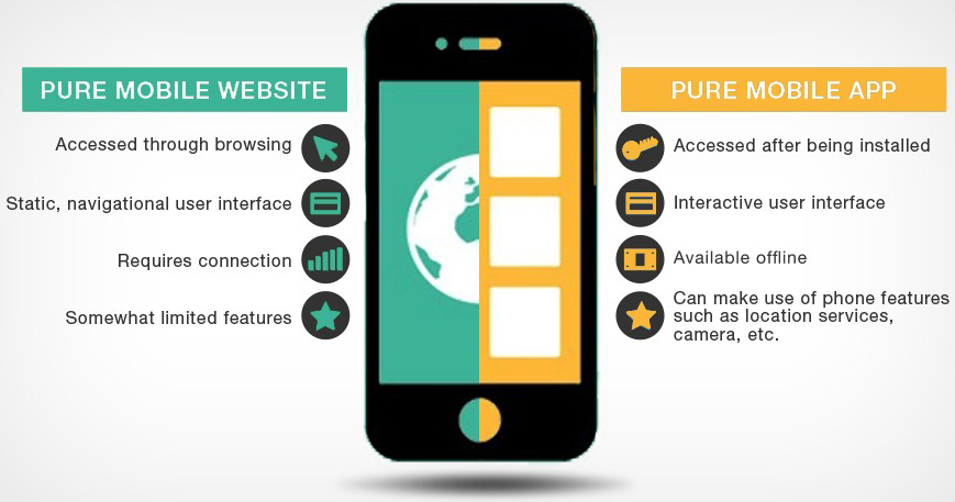
Each category has its own pros and cons, so the choice must be made by carefully assessing the different conditions and the whole context. When designing a real-time navigation system for use within a healthcare facility, the main target is to offer the service to the widest possible range of people. Therefore, at first, a responsive website could probably be the best solution thanks to its large compatibility and simplicity of implementation, not requiring any download or installation steps. However, a mobile application can be deemed the most appropriate choice in order to smoothly interact and communicate with users and make the most out of many smartphone features [28, 29]. Mobile applications provide an interactive interface, making users prefer them to the static navigational experience offered by websites (Fig. 2). Besides, mobile applications are available also in offline mode and can make use of needed phone features such as location services and camera (Fig. 3). In the case of a native app, however, the difficulty of implementation caused by non-compatibility features across multiple operating systems together with higher maintenance costs must be also taken into account.
Figure 1.
The hospital is provided with an elaborate signage system, making use of vertical and horizontal signs, consisting in coloured strips along the corridors, pointing the users to elevators and other points of interest.
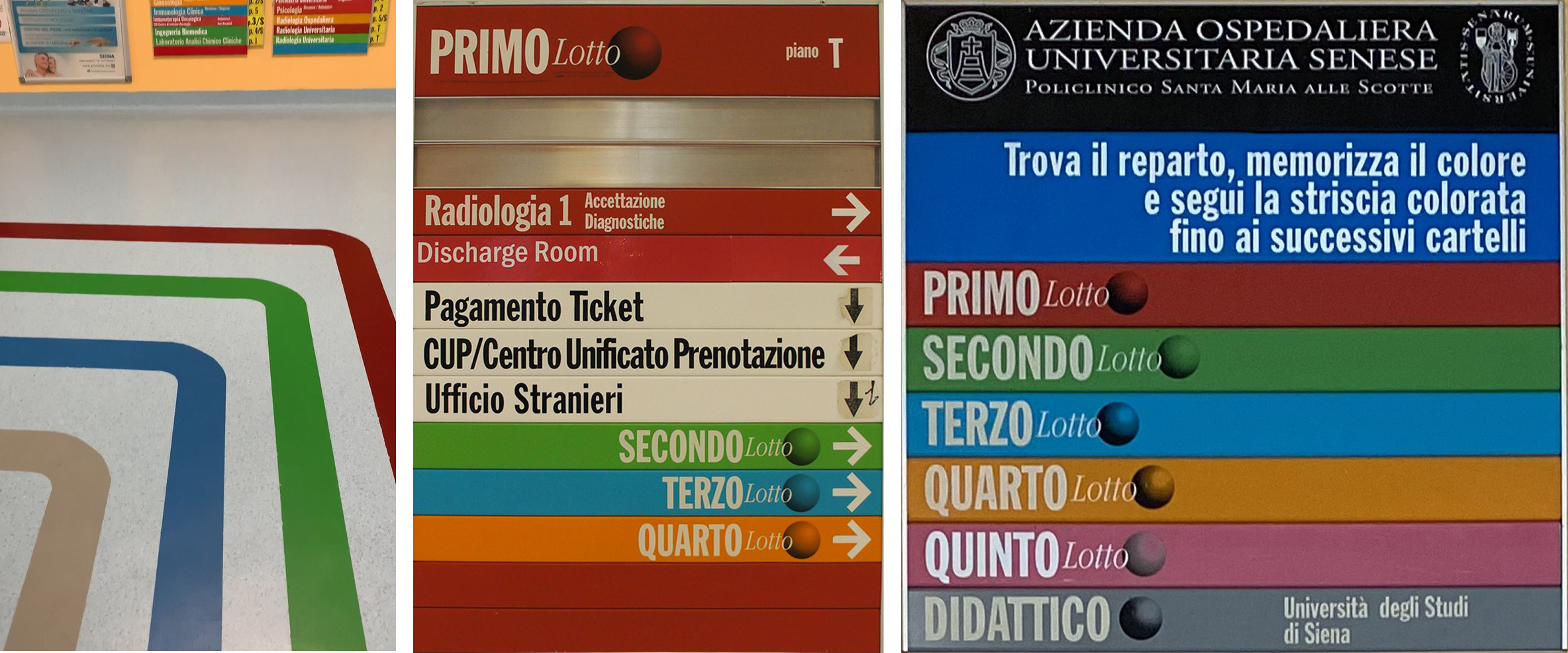
Figure 2.
Average time spent per day by mobile internet users in US through 2019. Source: eMarketer.
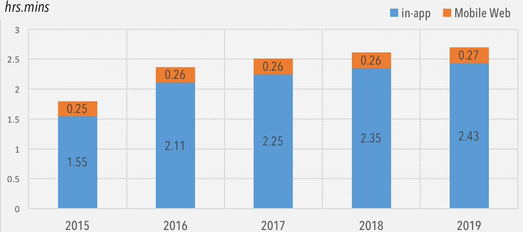
Figure 3.
Main differences between mobile applications and mobile web-sites.
In consideration of the previous aspects, we opted for a cross-platform hybrid application as the best developing architecture. Even with lower performance in terms of speed, it is less expensive (both in terms of time and costs), especially in terms of future maintenance and updating.
The main available cross-platform deploying frameworks have been identified in past studies [30]:
• Xamarin replicates native performance via C# wrappers, and the platform is very close to native programming through a cross-platform environment. Xamarin is open-sourced but only for non-commercial use. Developers require a community license for Xamarin, and businesses require enterprise and professional licenses.
• Flutter framework is a closed ecosystem running on Dart programming language. Applications made with Flutter consist of widgets, which can be considered app’s ‘building blocks’. Being supported by Google and an ever-growing community, Flutter comes with an extensive library of widgets for developing modern and beautiful mobile applications.
• Apache Cordova is a community project, letting you build mobile apps for various mobile platforms with one unique code base, as you develop your app with web technologies (HTML5, Javascript and CSS3) instead of relying on platform-specific (native) APIs like those of Android, iOS, or Windows Phone. The main disadvantage is performance because rendering is done via web-views instead of platform’s native UI (User Interface) framework.
• Ionic Framework is a set of CSS classes and a library of Javascript directives and modules, built on top of Cordova, with AngularJS. The main differences with Apache Cordova are that Ionic provides frameworks to use in the application, whereas Cordova provides plugins to run the application similar to the native app. Moreover, Ionic provides many different functions, which need to be integrated with the application, whereas Cordova provides the hardware access of a device to the application. Performance are instead quite equivalent.
• PhoneGap is a version of Cordova developed by Adobe. It has been marked as discontinued since October 1st, 2020 with Adobe announcing the end of development for PhoneGap and PhoneGap Build and the end of its investment in Apache Cordova project.
• React Native is an open-source framework created by Facebook to develop native cross-platform apps. UI components of React Native are similar to the native UI views and this offers faster rendering times compared to Cordova which has web-based frameworks. On the other hand, Cordova creates smaller build packages, and it has a better build performance than React Native. Moreover, Cordova makes it easy to bundle an existing web application into a Cordova application and reuse the same code, while in React developers can’t simply take the code they used to build a web application and repackage it for mobile.
Applications developed with each of the above-mentioned framework (but Xamarin) are said to be hybrid, meaning that they are neither truly native mobile application (because all layout rendering is done via web views instead of the platform’s native UI framework) nor purely web-based (because they are not just web apps, but are packaged as apps for distribution and have access to native device APIs).
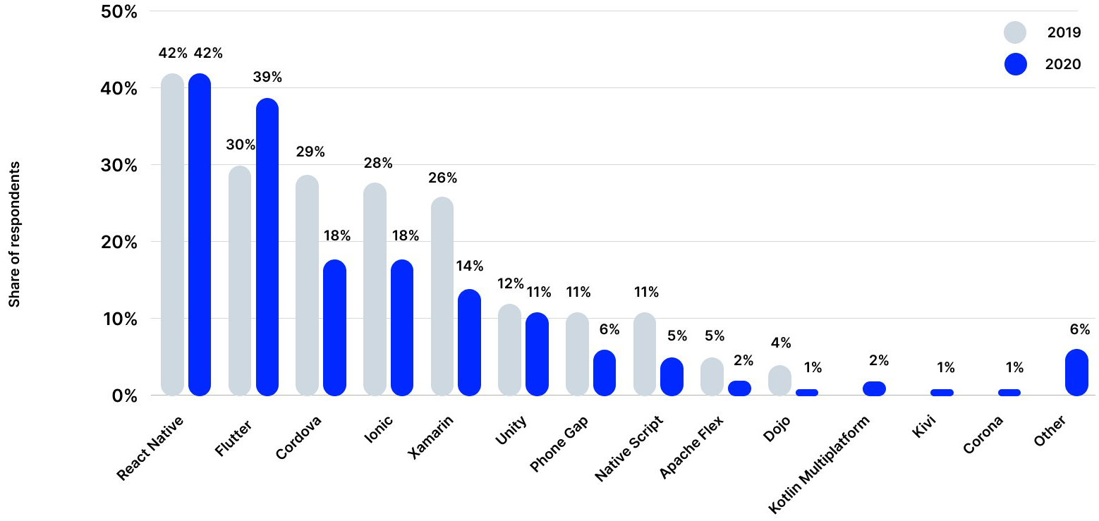
Apache Cordova has been chosen among the various possibilities because it provides all the functions needed to develop the prototype target application (access to the device hardware such as accelerometer, gyroscope, camera), whilst maintaining a very low learning-curve (unlike Xamarin, Flutter and React), an active community and documentation (unlike PhoneGap), native Javascript programming and still being among the top mobile app development frameworks in 2019–2021 (Fig. 4).
Figure 4.
Top mobile app development frameworks 2019–2021. Source: Statista at https://www.statista.com/statistics/869224/worldwide-software-developer-working-hours.
2.5Development methodology
System architecture must be defined in advance in order to reduce the complexity, solve architectural problems, reduce development time and costs and provide a proper work management. Unified Modeling Language (UML) is a common visual modelling language, rich in both semantics and syntax, used
Figure 5.
Use case diagram for on-site mode.
Figure 6.
Use case diagram for off-site mode.
for the architecture, design and implementation of complex software systems both from a structural and behavioural point of view. For this manuscript, UML diagrams of use cases, classes, activities and sequences have been designed.
The application offers two different navigation modes, depending on the actual position of the device while using the app: on-site and off-site. In on-site mode (Fig. 6), users have the possibility to search for the destination, view the proposed route and then proceed with the navigation. This mode is available only when users are located within the navigable area of the hospital. The search for the destination can be carried out in different ways, each of which is represented by a specific application icon:
• Facility: the application shows a list of pre-assigned points of interest, associated with the main junctions between adjacent pavilions, elevators and services.
• Name: the search is performed by name and last name of the desired physician or technician.
• Room: the search is made by using the actual room code.
After selecting the desired destination, the route is displayed allowing the user to start the navigation. In on-site mode, users also have the possibility to access a list of planned routes, select one of them and then proceed with the navigation.
Instead, in off-site mode (Fig. 6), users can visualise and then save a given path without actual being at the hospital. This mode is always available, regardless of the position of the device, allowing users to plan a navigation. The destination is chosen by using the same search methods proposed in on-site mode. Then the route is displayed and it can be saved or edited by adding further sections: each section will have the destination of the previous one as its starting point, and a new destination selected using one of the available methods. By accessing the saved routes, users can visualise them on the map or delete them if desired: this feature is available in both modes.
3.Results
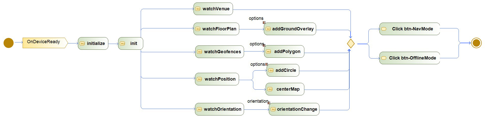
When the application starts (Fig. 7), the onDeviceReady event is called to ensure that the mobile device has an active data connection and it is ready to use. Then the initializing methods, which declare the main global variables and functions, are called. Here the connection with IndoorAtlas framework, Google Maps module and local CAFM system are also established using the provided API-keys. The authentications must be run before any other owning methods can be used.
3.1Linking the application with the Computer-Aided Facility Management system of the hospital
The hospital of Santa Maria alle Scotte has an internally developed custom CAFM system, named SPOT, which is a tool that allows the analysis of spaces and the organization and evaluation of hospital data and parameters [31, 32].
SPOT’s main relational database is a Microsoft SQL Server instance installed on a dedicated hospital data-server. The core module has been developed as a Windows Forms Application within Microsoft .NET Framework.
For the development of the indoor navigation system, it is useful to take advantage of the existing SPOT system. In fact, the coordinates and plans of floors with information about Operating Units (OUs), rooms, offices and all those places that can be considered points of interest can be provided by the system itself. At the same time, it is important to avoid to directly expose the hospital inner network to external users, in order to preserve the integrity of the contained data and reduce possible cybersecurity attacks.
Figure 7.
Activity diagram of application start. watchVenue, watch-FloorPlan, watchGeofences, watchPosition and watchOrienta-tion are IndoorAtlas methods while addGroundOverlay, ad-dPolygon, addCircle are Google Maps methods.
For this reason, a new set of WebAPIs have been developed within Microsoft .NET Framework and then installed on a web-server connected both to the inner and outer (i.e. exposed to the web) network. Hardware and software firewalls, together with SSL encryption, provided the required levels of logical separation between the two networks. The APIs operate as an intermediary layer between the mobile application installed on the user’s mobile and the SPOT system. Besides, it is essential to protect the privacy of users while they are using the app. For this reason, no personal username and password are requested during the authentication phase. Only a common set of credentials and an API-key are used instead. In this way, the user is not associated with an individual person and no user’s sensitive data are sent across the network.
3.2Authentication and data protection
The application authenticates itself with specific API keys on IndoorAtlas and Google Maps frameworks, as well as on the SPOT system. While authorization with third-party solutions is demanded on their inner architecture (documentations are available on owners’ websites [33, 34]), the authentication with SPOT has been developed from scratch, upgrading the current release of the system with a dedicated module. The application authenticates itself on the system using Basic Authentication security protocol with an HTTP POST method to the dedicated API controller, sending a Base64-encoded username and password within the request header. As stated above, this login method avoids users to actually personally sign-in to the system, preventing personal information and identity theft, while assuring a virtual identity confirmation and authorization at the same time. If the authentication is successful, the system returns a JWT (JSON Web Token) valid for the next 24 hours, which the application will use to authenticate itself in future API calls via Bearer Authentication security protocol.
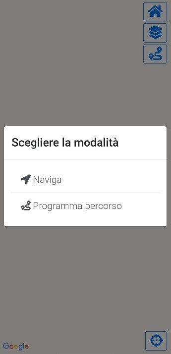
Figure 8.
Available modes.
3.3Developed interface and navigation modes
Once authentication has been provided, the application is ready to run. The designed interface prompts the user to choose between one of the two proposed modes (Fig. 8):
Figure 9.
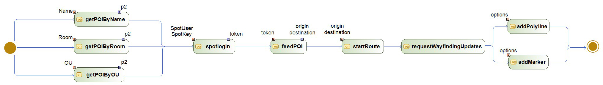
Activity diagram for selecting points of interest.
• Navigate: it is the on-site navigation and it starts when the user clicks the corresponding button btnNavMode;
• Plan route: it represents the off-site planning mode and it stars by clicking the button btnOfflineMode.
3.3.1Off-site mode
Figure 10.
Preliminary stages for off-site mode.
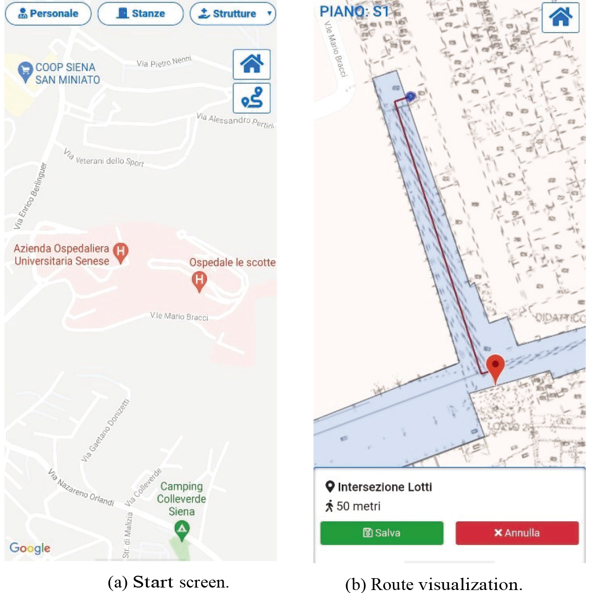
This mode can be selected by users who are not physically on the venue and want to plan and save a route. Users can choose the destination, the starting point, visualize the route and eventually save it in the mobile’s storage (Fig. 9). Three distinct routines are available for searching the desired destination POI (Fig. 10a): by choosing the endpoint among a list of pre-designed useful destination (getPOIByOU), by inputting the room code if it is known (getPOIByRoom) or by searching a physician’s name (getPOIByName). Likewise, the starting point must be selected among a list of fixed locations which correspond to the main entrances to the hospital. The available POIs are listed as follows and theirs position on the map are shown in Fig. 14:
1. Entrance
2. Blood Sampling Point
3. Buildings Intersection
4. Building 1 Lifts
5. Building 4 Lifts
6. Playroom
7. Emergency Department Lifts
8. Building 2 Lifts
9. Cafeteria
10. Building 3 Lifts
The coordinates of starting and ending points are given as input to the startRoute method, which requires the calculation of the route through the IndoorAtlas framework.
The app displays a map of the building’s storey, with the navigable area highlighted in blue, the planned route highlighted in red, the beginning location marked with a blue dot, and the destination marked with a red marker. Moreover, information about the total length of the route is displayed at the bottom (Fig. 10b). Lines, shapes and markers are drawn onto the map through the addPolyline and the addMarker methods of Google Maps.
The user can eventually save the planned route inside the mobile’s memory by pressing the green ”Save” button at the bottom-left corner of the screen. The app prompts the user to enter a custom name for the route (Fig. 11a). The routine stores the coordinates and the floor number of both the destination and the starting point in JSON format inside the device’s internal memory. If the user wishes to insert an additional leg for the current route (Fig. 11b), the whole activity is repeated and the destination of the previous leg will be automatically stated as the new starting point. The operation can be further iterated endlessly.
Figure 11.
Saving route, adding a new leg and display saved routes in off-site mode.
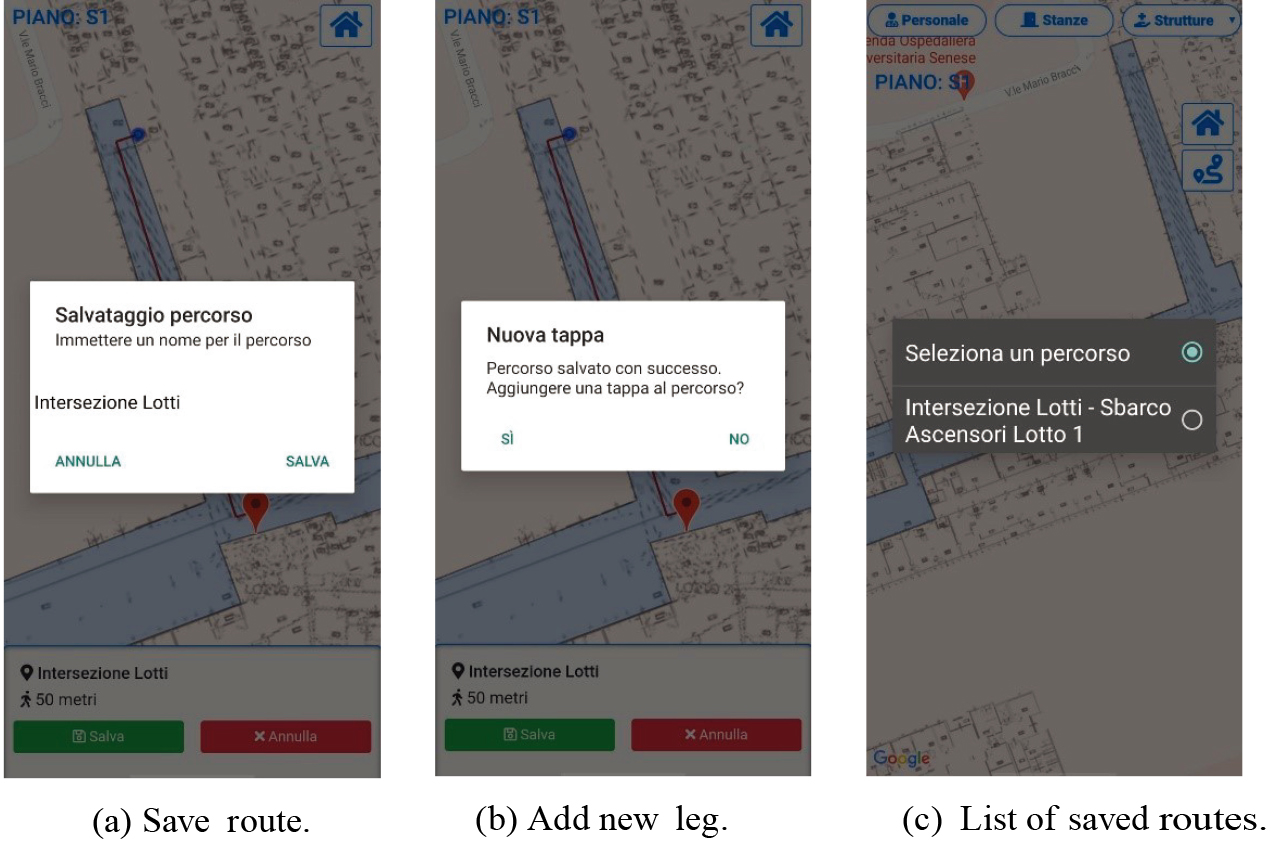
The user can then click the “Route” button (right below the “Home” button – Fig. 10a) to access the list of saved routes, possibly selecting or deleting them by choosing from the available options (Fig. 11c).
3.3.2On-site mode
In on-site mode, the user can actually navigate within the hospital. The destination can be selected by:
• choosing a point of interest through the three different routines described in the previous section and outlined in Fig. 9;
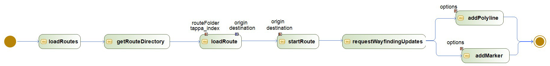
• starting from a previously saved route: the loadRoutes method loads the available saved routes (Fig. 12). Once the desired one is chosen, the coordinates of the stored destination point are passed to the IndoorAtlas framework to evaluate the shortest route in relation to the current user’s location.
Figure 12.
Activity diagram for loading the saved routes.
The route is then displayed by using Google Maps framework. Notice that the current user’s location is used as starting point despite the one which had been chosen in off-site mode, which served just for reference and planning purposes.
Figure 13.
Route loading and navigation for on-site mode.
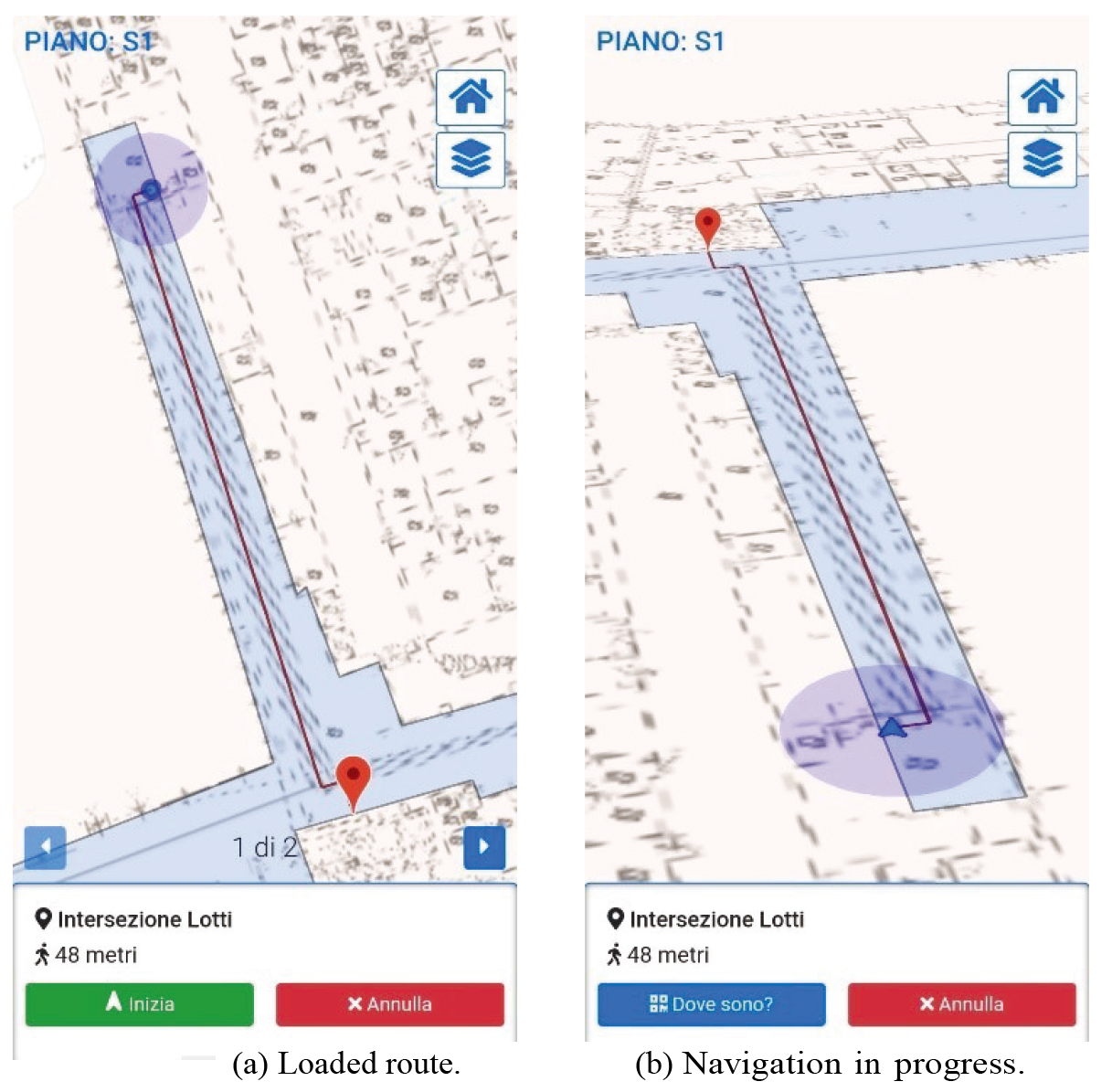
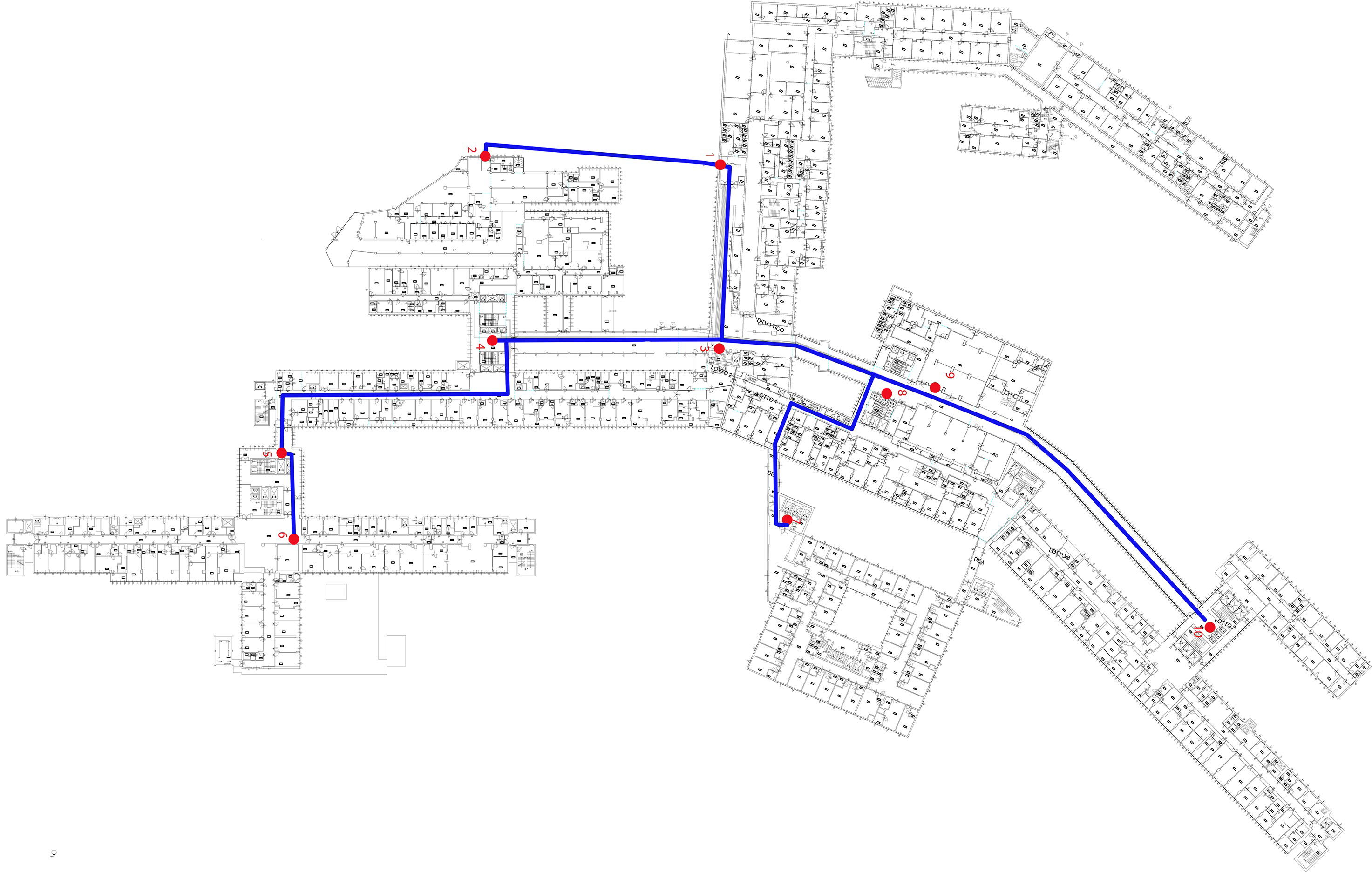
Figure 14.
Map of tested ground storeys of six adjacent pavilions of the Hospital Le Scotte, Siena (Italy) with navigable POIs and paths.
After the route is displayed, the user can proceed to the actual navigation by clicking the “Start” button (Fig. 13a). The current point locator is substituted with a blue arrow-shaped locator. An approximation blue circle is also displayed around the location marker. The radius of the circle specifies the precision of the IPS, being proportional to the error of the positioning system (Fig. 13a and b). In navigation mode, the map’s orientation is no more referred to fixed cardinal signs, but to the actual orientation of the device. A tilt is also performed on the map itself, which becomes oriented in relation to the direction the device is actually pointing to (Fig. 13b). These displaying variations are useful to differentiate the navigation activity from the previous map and route visualization. The IndoorAtlas method requestWayfindingUpdates is recursively called until the destination is reached. During the navigation, the locator follows the movement of the device and moves along the path. Once the destination is reached, the application prompts the user accordingly. The user can always stop the navigation at any time by clicking the red “Cancel” button at the bottom-right side of the screen. Once the user arrives at his destination, the application notifies him that the navigation has been performed successfully, the route is erased from the map, and the device returns to its normal view.
3.4Testing and implementation
A demo version of the app has been tested to assess the positioning error and the tolerance of the IPS on hospital areas where the magnetic field and WiFi signals had been previously acquired (no BLE beacons installed). Positioning error is defined as the offset between the actual position and the displayed locator, while tolerance represents the margin of error for each measurement and it is defined as the value of the radius of the approximation circle. Tests have been conducted on Android OS using a Xiaomi MI Mix smartphone with an active data connection on the ground storeys of six adjacent pavilions for a total surface of 12,438 sqm.
3.4.1Test 1
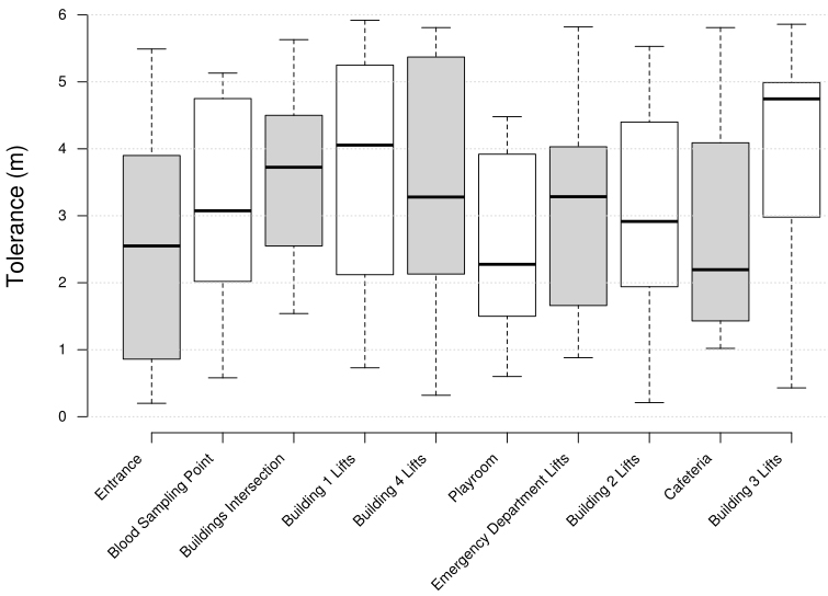
The first conducted test has been carried out to measure the positioning error and the tolerance for each available POI. Each measurement has been taken 10 times in each site. Results are shown in Figs 15 and 16.
Figure 15.
Box plots of positioning errors for each navigable POI (test 1).
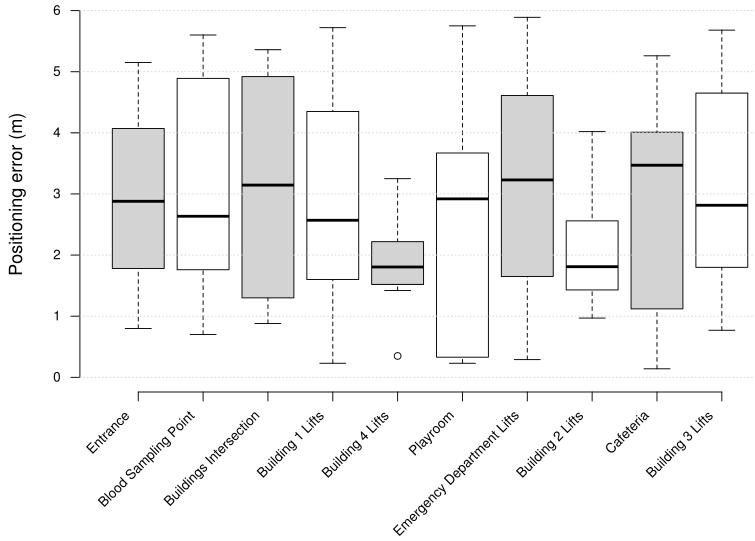
Figure 16.
Box plots of tolerances for each navigable POI (test 1).
3.4.2Test 2
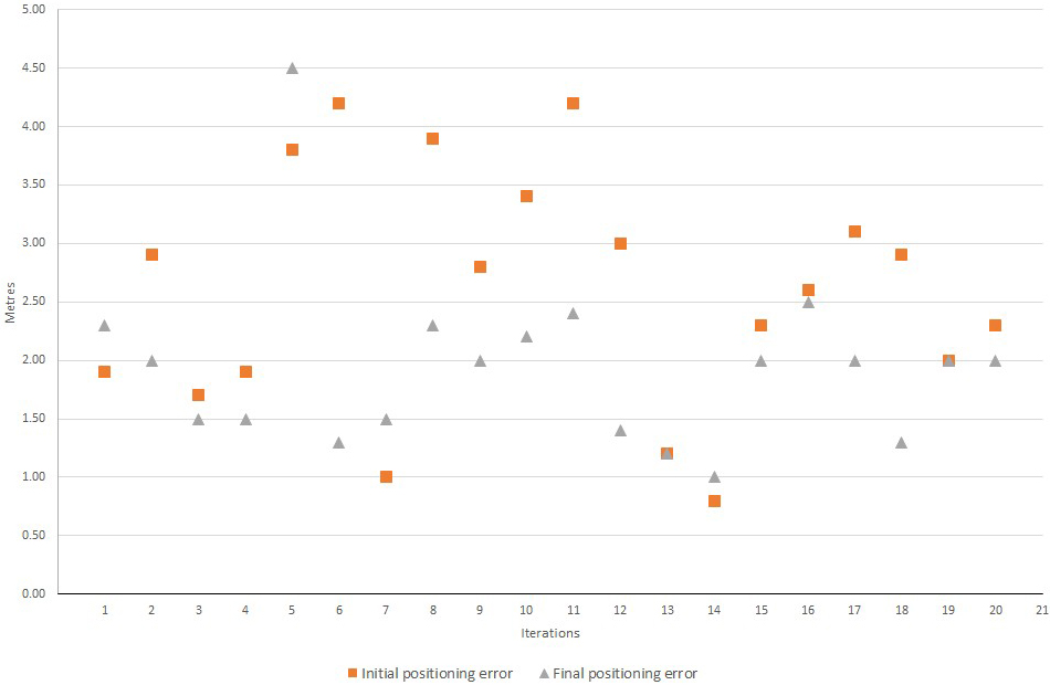
The accuracy of the IPS has been also tested in free-navigation mode (i.e., no destination selected). A closed loop of about 214 m (from POI 3 – Buildings Intersection – to POI 8 – Building 2 Lifts – and back) has been travelled with an average speed of 1.38 m/s. The test has been repeated 20 times. Initial and final values of positioning error have been measured for each iteration (Fig. 17).
Figure 17.
Initial and final positioning error for 20 iterations of a closed loop free-navigation between POI 3 and POI 8 (test 2).
3.4.3Test 3
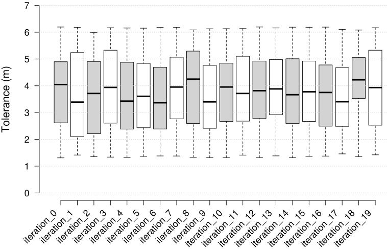
The third and final test measured the accuracy and the tolerance of the system during navigation in on-site mode. The chosen route was from the main entrance of the hospital (POI 1) to the lifts of Building 4 (POI 5). The total length is about 206 m. Navigation has been repeated 20 times with an average speed of 1.38 m/s. For each iteration the positioning error between the physical position and the displayed marker of the destination has been measured (Fig. 18). Moreover, the value of the approximation radius has been sampled every 2 s during every navigation to evaluate the trend of the tolerance of the IPS during navigation (Fig. 19).
Figure 18.
Plot of destination accuracy (positioning error) trend through 20 iterations of a navigation between POI 1 and POI 5 in on-site mode (test 3).
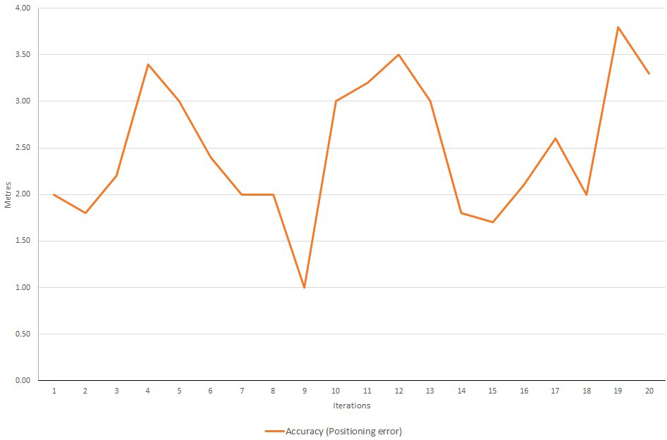
Figure 19.
Box plots of tolerances for each iteration of test 3.
4.Discussion
The assessment of results of the implemented tests showed accuracy and tolerances consistent with results from the literature in comparable settings [35]. In particular, the average positioning error for the three tests is comparable, with other WiFi Received Signal Strength (RSS) fingerprint-based IPS (Table 2).
Table 2
Positioning error calculated for the three performed tests compared to the one of other WiFi Received Signal Strength (RSS) fingerprint-based IPS [35]
| Framework | Eaverage (m) | |
|---|---|---|
| Developed IPS (Test 1) | 2.75 | 1.60 |
| Developed IPS (Test 2) | 2.27 | 0.93 |
| Developed IPS (Test 3) | 2.49 | 0.73 |
| Other WiFi RSS fingerprint-based IPS | 4.13 | 2.12 |
The current configuration of the developed IPS with only WiFi signals and magnetic field fingerprinting allows a navigation throughout alleys and areas where the destinations are spaced at least 2.75
Moreover, the results of test 2 highlight that the positioning error tends to decrease while the device is moving. As a matter of fact, Fig. 17 shows that the final positioning error is lower than the initial one in 16 out of 20 performed iterations. The cause of this behaviour is not determined, yet. It could be due to bugs of third-party positioning framework, to erroneous preliminary mapping or to other causes which will have to be further investigated in future works.
5.Conclusions
The goal of this work was to design and develop an indoor positioning system for healthcare premises dedicated to patients, visitors and staff to find their bearings throughout the hospital, and also to be used for empowering specific routing tools, such as the navigation for the evacuation of hospitalized patients [36]. The case study is the Santa Maria alle Scotte hospital campus in Siena, Italy. A previous study reviewed all the technologies which are currently available for indoor positioning. The most suitable have been chosen according to the peculiarities of the target hospital and inner organization. The chosen framework relies on sensor fusion (Earth magnetic fields, WiFi and BLE) and dead-reckoning systems. The implementation is based upon existing third-party frameworks for geolocation and displaying (IndoorAtlas and Google Maps). A custom designed controller has also been developed to interface the application to the hospital’s CAFM via APIs for retrieving the coordinates of the available points of interest.
In terms of software designing, a hybrid architecture has been chosen as the most compelling solution. The strong degree of interaction, compatibility and adaptation to different types of mobile operating systems and platforms, together with ease of maintenance have been the main factors which affected the decision. Apache Cordova is the chosen framework for developing the application. It allows to use standard web language for mobile platforms, avoiding specific developments in different programming languages for each target OS.
UML schemas have been used in the designing process. Diagrams of use cases, classes, activities and sequences have been implemented for the description of the functionalities and the structure of the application.
Tests have been conducted to assess the accuracy (i.e., positioning error) and the tolerance (uncertainty of the displayed position) of the IPS in on-site mode. In particular, tests focused on measuring the offsets between real and displayed position together with the values of the approximation radius in each one of the available POI (test 1), during a closed loop free-navigation (test 2) and along a navigation path (test 3). The performances are comparable to those achieved in other studies [35] and could be further improved by implementing BLE beacons into the infrastructure of the IPS.
Future works will concern evaluating heuristics and carrying out usability tests for different categories of users according to the current legislation and technical standards, in order to check and improve the ergonomics of the application interface.
Acknowledgments
The authors thank the Azienda Ospedaliero Universitaria Le Scotte top managers for their collaboration in the design and test phases.
Conflict of interest
The authors declare that they have no conflict of interest.
References
[1] | Chen CH, Chang WC, Chang WT. Gender differences in relation to wayfinding strategies, navigational support design, and wayfinding task difficulty. Journal of Environmental Psychology. (2009) ; 29: (2): 220-226. |
[2] | McNamara TP, Sluzenski J, Rump B. 2.11 – Human Spatial Memory and Navigation. In: Byrne JH, ed. Learning and Memory: A Comprehensive Reference. Oxford: Academic Press; (2008) . pp. 157-178. |
[3] | Montello DR. Navigation. In: The Cambridge Handbook of Visuospatial Thinking. Cambridge University Press; (2005) . pp. 257-294. |
[4] | Arthur P, Passini R. Wayfinding: people, signs, and architecture. New York: McGraw-Hill Book Co.; (1992) . |
[5] | Kallai J, Makany T, Csatho A, Karadi K, Horvath D, Kovacs-Labadi B, et al. Cognitive and affective aspects of thigmotaxis strategy in humans. Behavioral Neuroscience. (2007) ; 121: (1): 21. |
[6] | Raper J, Gartner G, Karimi H, Rizos C. A critical evaluation of location based services and their potential. Journal of Location Based Services. (2007) ; 1: (1): 5-45. |
[7] | Brimicombe A, Li C. Location-based services and geo-information engi-neering. Vol. 21. John Wiley & Sons; (2009) . |
[8] | Lin XY, Ho TW, Fang CC, Yen ZS, Yang BJ, Lai F. A mobile indoor positioning system based on iBeacon technology. In: 2015 37th Annual International Conference of the IEEE Engineering in Medicine and Biology Society (EMBC); (2015) . pp. 4970-4973. |
[9] | Smieszek T, Lazzari G, Salath’e M. Assessing the dynamics and control of droplet-and aerosol-transmitted influenza using an indoor positioning system. Scientific Reports. (2019) ; 9: (1): 1-10. |
[10] | P’erez-Navarro A, Torres-Sospedra J, Montoliu R, Conesa J, Berkvens R, Caso G, et al. Challenges of fingerprinting in indoor positioning and nav-igation. In: Geographical and Fingerprinting Data to Create Systems for Indoor Positioning and Indoor/Outdoor Navigation. Elsevier; (2019) . pp. 1-20. |
[11] | Mendoza-Silva GM, Torres-Sospedra J, Huerta J. A Meta-Review of Indoor Positioning Systems. Sensors. (2019) ; 19: (20). |
[12] | Wichmann J. Indoor positioning systems in hospitals: A scoping review. Digital Health. (2022) ; 8: : 1-20. |
[13] | Luschi A, Miniati R, Iadanza E. A Web Based Integrated Healthcare Facility Management System. In: IFMBE Proceedings. Vol. 45; (2015) . pp. 633-636. |
[14] | Iadanza E, Luschi A, Gusinu R, Terzaghi F. In: Designing a Healthcare Computer Aided Facility Management System: A New Approach. Vol. 73; (2020) . pp. 407-411. |
[15] | Iadanza E, Luschi A, Ancora A. Bed Management in Hospital Systems. In: IFMBE Proceedings. Vol. 68; (2019) . pp. 313-316. |
[16] | Iadanza E, Chini M, Marini F. Electromagnetic Compatibility: RFID and Medical Equipment in Hospitals. In: IFMBE Proceedings. Vol. 39; (2013) . pp. 732-735. |
[17] | Mariappan PM, Raghavan DR, Abdel Aleem SHE, Zobaa AF. Effects of electromagnetic interference on the functional usage of medical equipment by 2G/3G/4G cellular phones: A review. Journal of Advanced Research. (2016) ; 7: (5): 727-738. |
[18] | Perez-Navarro A, Montoliu R, Torres-Sospedra J, Conesa J. Magnetic Field as a Characterization of Wide and Narrow Spaces in a Real Challenging Scenario Using Dynamic Time Warping; (2018) . |
[19] | Ibrahim M, Nabil T, Halawa HH, ElSayed HM, Daoud RM, Amer HH, et al. Fuzzy-based Wi-Fi localisation with high accuracy using fingerprinting. International Journal of Systems, Control and Communications. (2018) ; 9. |
[20] | Taşkan AK, Alemdar H. Obstruction-aware signal-loss-tolerant indoor po-sitioning using bluetooth low energy. Sensors (Switzerland). (2021) ; 21. |
[21] | Cheng L, Chang H, Wang K, Wu Z. Real Time Indoor Positioning System for Smart Grid based on UWB and Artificial Intelligence Techniques; (2020) . |
[22] | Yamashita K, Oyama S, Otani T, Yamashita S, Furukawa T, Kobayashi D, et al. Smart hospital infrastructure: Geomagnetic in-hospital medical worker tracking. Journal of the American Medical Informatics Association. (2021) ; 28. |
[23] | Chen L, Wu J, Yang C. MeshMap: A Magnetic Field-Based Indoor Navi-gation System with Crowdsourcing Support. IEEE Access. (2020) ; 8. |
[24] | Forsyth D, Ponce J. Computer Vision: A Modern Approach. (Second edition). Prentice Hall; (2011) . |
[25] | Ng XH, Lim WN. Design of a Mobile Augmented Reality-based Indoor Navigation System; (2020) . |
[26] | Cheng CH, Wang TP, Huang YF. Indoor positioning system using artifi-cial neural network with swarm intelligence. IEEE Access. (2020) ; 8: : 84248- 84257. |
[27] | Elmenreich W. An introduction to sensor fusion. Vienna University of Technology, Austria. (2002) ; 502: : 1-28. |
[28] | Charland A, Leroux B. Mobile application development: Web vs. Native. Commun ACM. (2011) ; 54: (5): 49-53. |
[29] | Nunkesser R. Beyond Web/Native/Hybrid: A New Taxonomy for Mobile App Development. In: 2018 IEEE/ACM 5th International Conference on Mobile Software Engineering and Systems (MOBILESoft); (2018) . pp. 214-218. |
[30] | Falleri N, Luschi A, Gusinu R, Terzaghi F, Iadanza E. Designing an Indoor Real-Time Location System for Healthcare Facilities. In: Mediterranean Forum – Data Science Conference. MeFDATA 2020. Communications in Computer and Information Science. Vol. 1343; (2021) . pp. 110-125. |
[31] | Iadanza E, Luschi A. An integrated custom decision-support computer aided facility management informative system for healthcare facilities and analysis. Health and Technology. (2020) ; 10: (1): 135-145. |
[32] | Iadanza E, Luschi A, Gusinu R, Terzaghi F. Designing a Healthcare Com-puter Aided Facility Management System: A New Approach. In: IFMBE Proceedings. Vol. 73; (2020) . pp. 407-411. |
[33] | Ltd I. IndoorAtlas API Documentation. Accessed: 2021-12-10. https://docs.indooratlas.com. |
[34] | LLC G. Cordova GoogleMaps plugin for iOS and Android. Accessed: 2021-12-10. https://github.com/mapsplugin/cordovaplugingooglemapsdoc/tree/master/v2.6.0. |
[35] | Kanaris L, Kokkinis A, Liotta A, Stavrou S. Fusing Bluetooth Beacon Data with Wi-Fi Radiomaps for Improved Indoor Localization. Sensors. (2017) ; 17: (4): 812. |
[36] | Iadanza E, Luschi A, Merli T, Terzaghi F. Navigation Algorithm for the Evacuation of Hospitalized Patients. In: IFMBE Proceedings. Vol. 68; (2019) . pp. 317-320. |

