
Preliminary study on the new wound monitoring technology using co-planar waveguide sensor: Modeling and simulation
Abstract
BACKGROUND:
Wound monitoring is very meaningful for the clinical research, diagnosis and treatment. But the existing wound monitoring technology is hard to meet the needs of modern medical care in terms of real-time, non-invasive and anti-interference.
OBJECTIVE:
To solve this problem, this paper proposed a new kind of monitoring technology based on the co-planar waveguide transmission line theory and assessed the application value of this method as a wound monitoring technology.
METHODS:
The simplified wound model included the skin, fat, muscle, tissue fluid and bandage and a new co-planar waveguide sensor were designed and established. All of the simulation was achieved in the electromagnetic special software. The data processing method was based on the transmission line theory.
RESULTS:
Detailed analyses of the results from the simulation were conducted. The sensor has a good monitoring effect in the low frequency band. The monitoring results could be influenced by the thickness of the bandage outside the wound. The thickness of the bandage should not be larger than 10 mm. The effective monitoring area of the sensor is 30
CONCLUSIONS:
The proposed sensor based on the CPW transmission principle in this paper has good wound monitoring potential.
1.Introduction
Wound healing is a very important and long process for patients. Wound monitoring can not only understand the injury in real time for effectively managing the wound [1], but also be helpful for clinical research and provides effective information for wound assessment and treatment plan [2]. As a result, wound monitoring is very meaningful for the wound healing process.
Modern wound monitoring should meet the environmental needs of mobile medicine. That means the monitoring technology should be efficient, accurate, convenient and non-invasive in order to adapt to various fields in reality such as engineering, military and so on. Existing wound monitoring technology is mainly based on the experience of clinical staff, using physical measurements such as wound area and depth [3, 4, 5] or physiological measurements such as cell migration experiments [6] for evaluation. However, these methods are not convenient and real-time. The development of physics image technology represented by the optical coherence tomography (OCT) in the 1990s brought new breakthroughs to wound monitoring technology [7, 8, 9]. These technologies have good real-time performance and meet high-precision and non-invasive requirements. However, the OCT detection is susceptible to interference from external factors such as bandages, drugs, blood flow, etc., and its cost is relatively high because of the sensitive optical instrument.
Co-planar waveguide (CPW) is a relatively new type of electromagnetic transmission line device [10, 11, 12]. Compared with traditional waveguides, CPW that can achieve transmitting electromagnetic waves in a plane has the characteristics of conformal and miniaturization. As a result, the real-time, non-invasive monitoring can be realized based on the CPW transmission method. And due to the better penetration of electromagnetic fields, the ability to resist external interference of CPW should be stronger than that of OCT. Therefore, CPW has a high potential as a wound monitoring technology.
In this paper, the effect of a new transmission method based on CPW on wound status detection was studied through simulation based on the electromagnetic transmission line theory. According to the simulation results, the application value of this method as a wound monitoring technology was assessed.
2.Methods
2.1Modeling of the wound of biological tissues
The simplified structure of hemorrhage injury was established to simulate the wound model of biological tissue, as shown in Fig. 1. The skin, fat, muscle, tissue fluid and bandage were contained in this structure. Blood was the main component of the tissue fluid.
Table 1
The four-order Cole-Cole parameters of tissues for the model
| Tissue |
|
|
|
|
|
|
|
|
|
| ||||
|---|---|---|---|---|---|---|---|---|---|---|---|---|---|---|
| Skin | 4.0 | 39.0 | 7.96 | 0.1 | 280 | 79.58 | 0 | 3e4 | 1.59 | 0.16 | 3e4 | 1.592 | 0.2 | 4e-3 |
| Muscle | 3.15 | 58.38 | 1.01 | 0.172 | 647.8 | 21.59 | 0.151 | 1245 | 4.17 | 0 | 37355 | 6.34 | 0 | 0.59 |
| Fat | 2.5 | 9.0 | 7.96 | 0.2 | 35 | 15.92 | 0.1 | 3.3e4 | 159.15 | 0.05 | 1e7 | 15.915 | 0.01 | 0.035 |
| Tissue fluid | 4.05 | 65.11 | 8.43 | 8e-3 | 595.6 | 11.06 | 6e-3 | 4889 | 1.94 | 0 | 17281 | 1.63 | 0 | 0.58 |
| Tissue fluid (solidified) | 3.75 | 58.18 | 1.09 | 3e-3 | 603.2 | 28 | 2e-3 | 2050 | 1.53 | 0 | 25530 | 1.01 | 0 | 0.03 |
Figure 1.
The simplified structure of hemorrhage injury for simulation: (a) the normal tissue model, (b) the hemorrhage injury model.
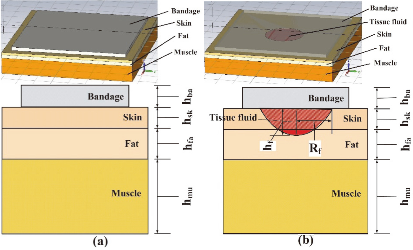
As shown in Fig. 1, the main physical size parameters in the model include the thickness of each layer of tissue and bandage (
(1)
2.2Design of the sensor
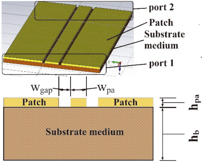
The CPW structure was designed and applied to the simulation of this article, as shown in Fig. 2. The electromagnetic field would be distributed on the patch and be transmitted between port 1 and port 2 along the depth direction of the sensor. The main physical size parameters of this CPW structure were thickness and width (
Figure 2.
The structure of the sensor for simulation.
2.3Analysis of the sensor
As shown in Fig. 2, when the port 1 and port 2 were connected to the vector network analyzer at the same time, the transmission parameter matrix S that describes the propagation characteristics of the electromagnetic field on the sensor can be measured. According to transmission line theory [17], the transmission scattering matrix S can be converted into the transmission impedance matrix Z of the sensor:
(2)
In Eq. (2),
The transmission characteristics of the electromagnetic field on the sensor could be affected by changing in the media surrounding the sensor because of the changing of the dielectric properties (
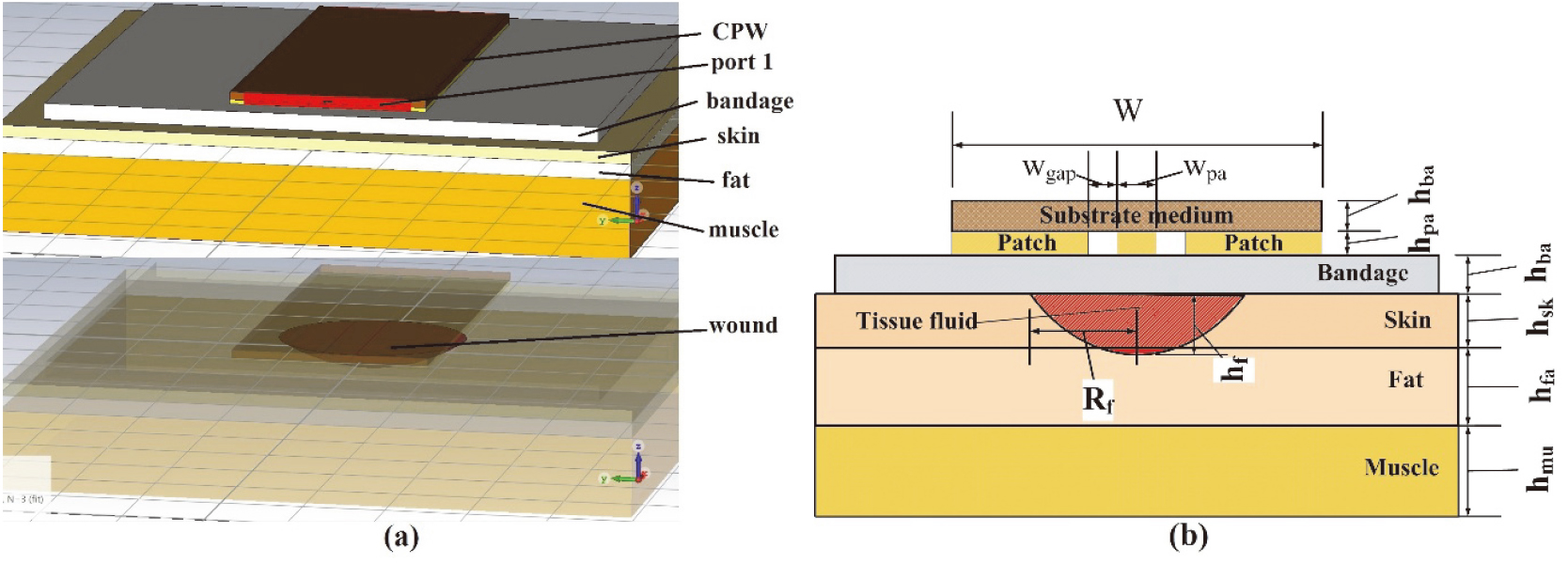
Figure 3.
The diagram of simulation settings: (a) simulation structure setting in CST (b) simulation structure size.
2.4Design of the simulation
Microwave Studio CST was used as the simulation software. Figure 3 shows the diagram of simulation settings. The sensor was attached to the surface of the bandage which wrapped around the wound. The wound was mainly composed of tissue fluid. The working frequency is set to 1–5 GHz. The structural parameters in the model are set as follows referring to the human physiological characteristics:
In the simulation, the tested tissue was mainly composed of three states: normal state, bleeding state, and healing state. In the bleeding state and the healing state, the wound was mainly composed of tissue fluid and tissue fluid (solidified) whose dielectric characteristic parameters were shown in Table 1. On the other hand, several parameters such as
3.Results and discussion
3.1Data processing
According to Eq. (2), the transmission impedance matrix Z was calculated by the transmission scattering matrix S derived after simulation. the reflected impedance and transmission impedance also met the conditions:
(3)
Figure 4.
The monitoring effect
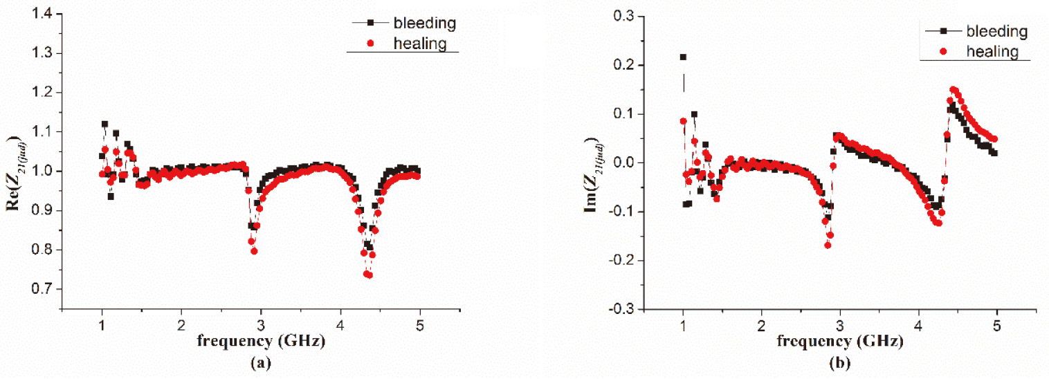
Figure 5.
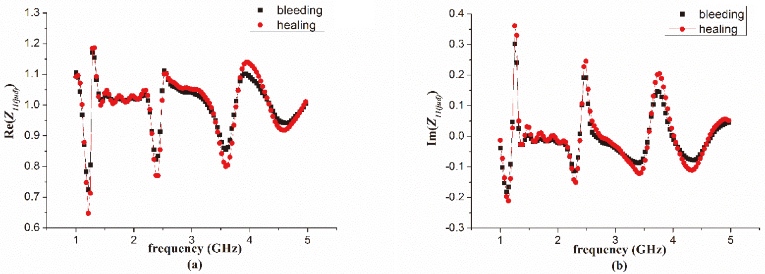
The monitoring effect
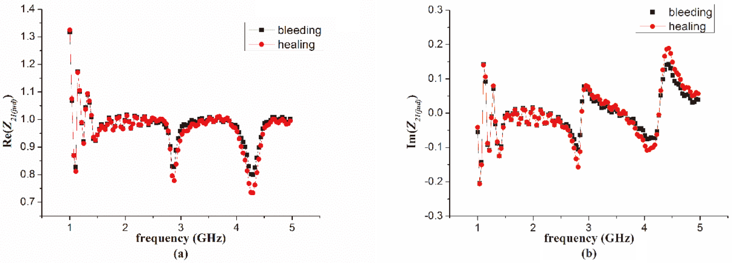
Figure 6.
The monitoring effect
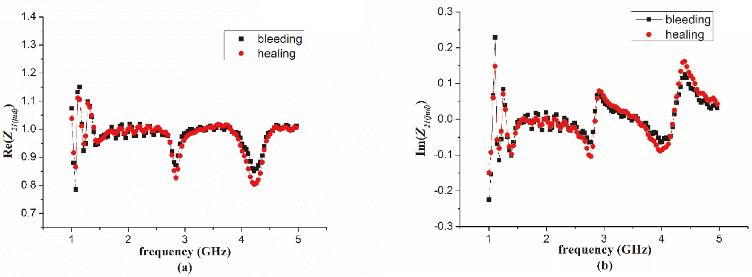
According to Eq. (3), the real part of normalization complex parameter
3.2Study of the monitoring effect Z 21(jud) W
The size parameters of the sensor designed by different team could be different. But most of the size parameters would not differ too much in order to make the characteristic impedance of the sensor equal to 50
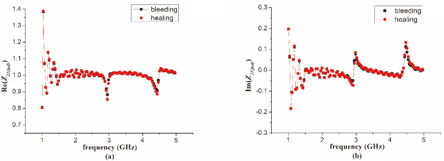
As shown in Figs 4–6, the real part and the imaginary part of
Comparing with Figs 4–6, it was found that the change of
3.3Study of the monitoring effect Z 21(jud) h 𝑏𝑎
Figures 7 and 8 show the monitoring effect
Figure 7.
The monitoring effect
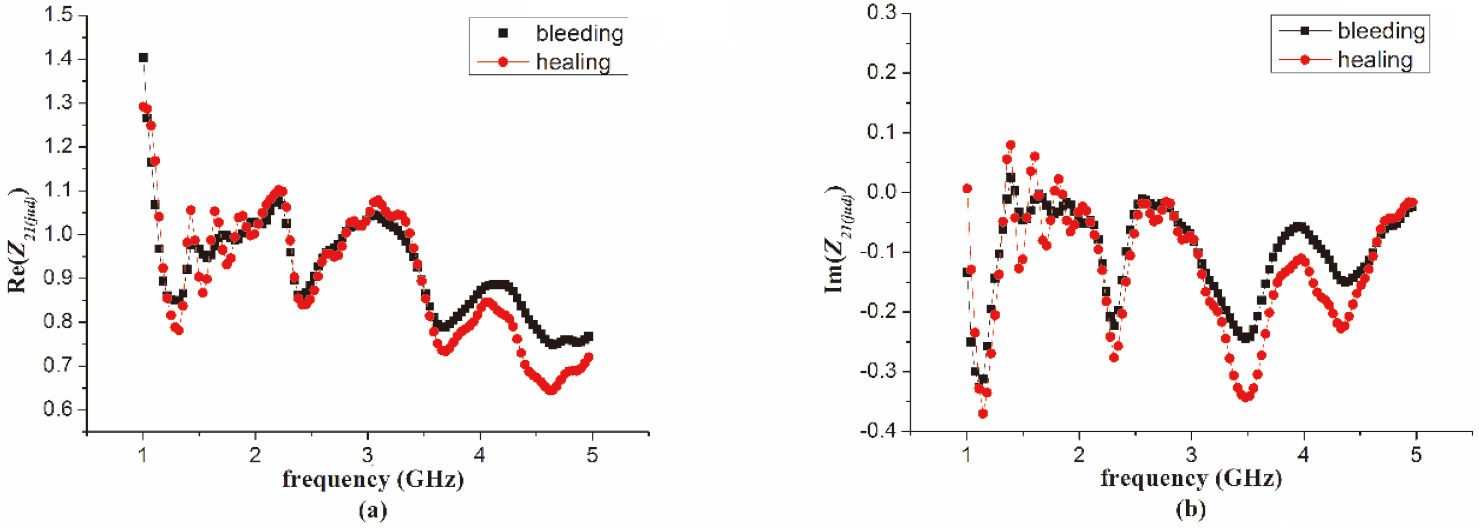
Figure 8.
The monitoring effect
As shown in Fig. 7, the best monitoring results of the sensor were achieved in the working frequency range, when the thickness of the bandage was thin (
3.4Study of the monitoring effect determined by Z 11 ( j u d )
According to the transmission line theory [17],
Figure 9.
The monitoring effect
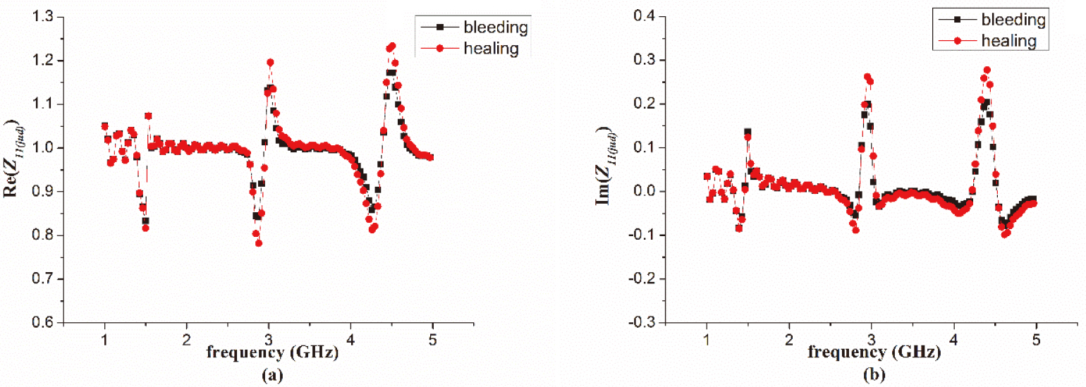
Figure 10.
The monitoring effect
As shown in Figs 9 and 10, there were also several resonance points at the high frequency band, where the sensor has also achieved better monitoring results. The resonance frequency points were consistent with the resonance frequency points in the monitoring results with
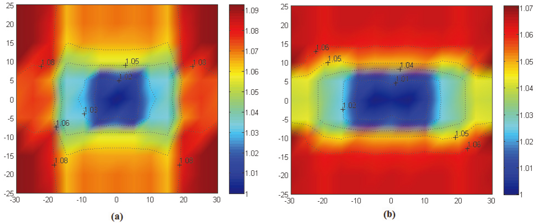
3.5Study on the range of the sensor monitoring area
In order to determine the effective monitoring area range of the sensor proposed in this paper, the monitoring effect
Figure 11.
The monitoring effect
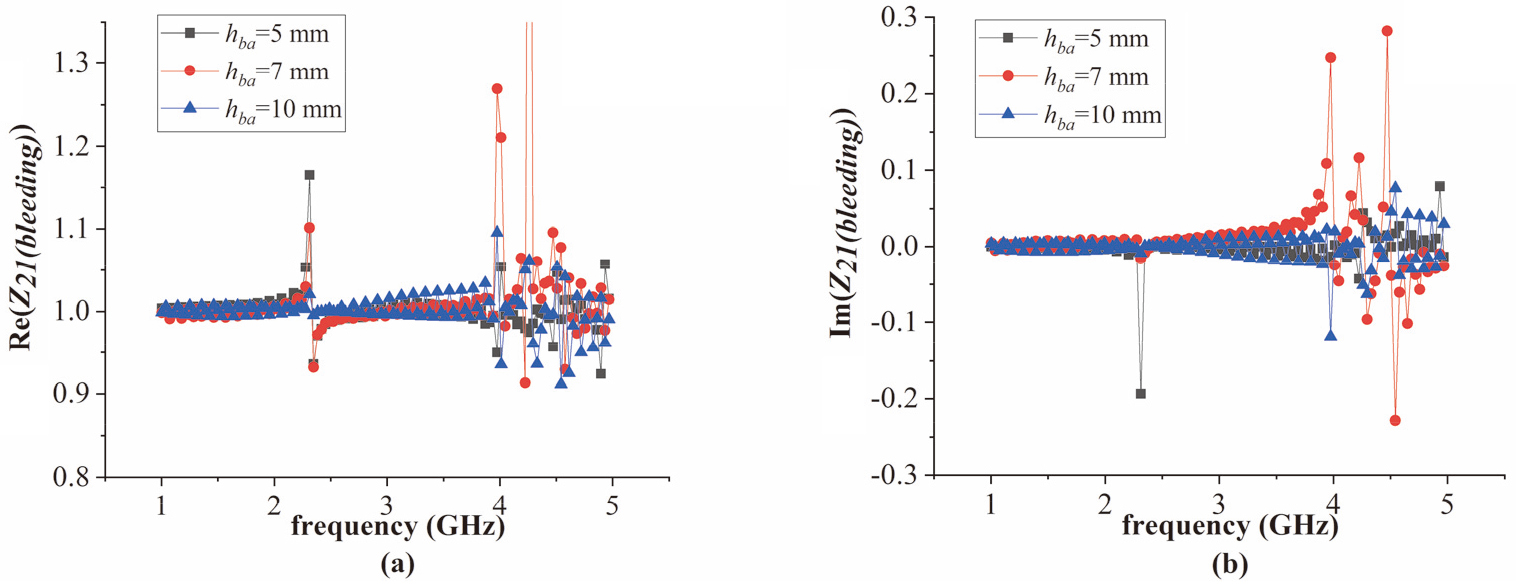
Figure 12.
The imaging results of real part of
As shown in Fig. 11, The real part and the imaginary part of
Sometimes the sensor may not be able to place on the center of the wound accurately. In order to determine the monitoring area size of the sensor, we changed the position of the sensor on the bandage plane in the simulation model in Fig. 3b and studied the monitoring effect. The thickness
In Fig. 12, the imaging results show the obvious numerical difference in the area of 30
4.Conclusion
According to the simulation results, the proposed sensor based on the CPW transmission principle in this paper has good wound monitoring potential. The sensor has a good monitoring effect due to the electromagnetic penetration in the low frequency band where is near the 1 GHz frequency point. The monitoring results would be influenced by the thickness of the bandage outside the wound. As a result, the thickness of the bandage should not be larger than 10 mm. The effective monitoring area of the sensor is 30
The results of the assessment of the wound monitoring ability of the sensor with
Acknowledgments
This research was supported by NSFC (No. 81671846), the National Key R&D Program (2019YFC0119103), and FSPTF (No. 2019-JCJQ-JJ-090).
Conflict of interest
None to report.
References
[1] | Gogia SB. A novel and accurate technique of photographic wound measurement. Indian Journal of Plastic Surgery. (2019) ; 45: (2): 425-429. |
[2] | Wang SC, Au Y, Ramirez JL, et al. The promise of smartphone applications in the remote monitoring of postsurgical wounds: a literature review. Advances in Skin & Wound Care. (2020) ; 33: (9): 489-496. |
[3] | Sattar H, Bajwa IS, Amin RU, et al. An IoT-based intelligent wound monitoring system. IEEE Access. (2019) ; 7: : 144500-144515. |
[4] | Smaropoulos E, Cremers NA. Medical grade honey for the treatment of paediatric abdominal wounds: a case series. Journal of Wound Care. (2020) ; 29: (2): 94-99. |
[5] | Pena G, Kuang B, Szpak Z, et al. Evaluation of a novel three-dimensional wound measurement device for assessment of diabetic foot ulcers. Advances in Wound Care. (2020) ; 9: (11): 623-631. |
[6] | Augustine R, Hasan A, Patan NK, et al. Titanium nanorods loaded PCL meshes with enhanced blood vessel formation and cell migration for wound dressing applications. Macromolecular Bioscience. (2019) ; 19: (7): e1900058-e1900072. |
[7] | Glinos GD, Verne SH, Aldahan AS, et al. Optical coherence tomography for assessment of epithelialization in a human ex vivo wound model. (2017) ; 25: (6): 1017-1026. |
[8] | Deegan A, Wang W, Men S, et al. Optical coherence tomography angiography monitors human cutaneous wound healing over time. Quantitative Imaging in Medicine and Surgery. (2018) ; 8: (2): 135-150. |
[9] | Chiu WK, Vien BS, Russ M, et al. Towards a non-invasive technique for healing assessment of internally fixated femur. Sensors. (2019) ; 19: (4): 857-870. |
[10] | Arshad S, Tahir FA, Rashid A, et al. Coplanar-waveguide fed circularly polarized antenna for wireless WLAN/LTE applications. Electromagnetics. (2020) ; 40: (5): 354-363. |
[11] | Nanda M, Kalavagunta Y, Rajareddy AV. A quad-band sierpenski based fractal antenna fed by coplanar waveguide. Microwave & Optical Technology Letters. (2020) ; 62: (2): 893-898. |
[12] | Mahajan RC, Parashar V, Vyas V, et al. Design and implementation of defected ground surface with modified co-planar waveguide transmission line. SN Applied Sciences. (2019) ; 1: (3): 251-262. |
[13] | Zhang L, Pang Y, Ding L, et al. The cole-cole model of porcine activity tissues in radio frequency. 10th International Congress on Image and Signal Processing & BioMedical Engineering and Informatics. (2017) ; 1-4. |
[14] | Gabriel S, Lau RW, Gabriel C. The dielectric properties of biological tissues: III. Parametric models for the dielectric spectrum of tissues. Physics in Medicine and Biology. (1996) ; 41: (11): 2271--2293. |
[15] | Sara A, Elham M, Karoliina K, et al. Design and optimization of mm-size implantable and wearable on-body antennas for biomedical systems. The 8th European Conference on Antennas and Propagation. (2014) ; 1-5. |
[16] | Jose A, Kappan SJ. High gain coplanar feed ultra-wide band wearable antenna using artificial magnetic conductors. 5th International Conference on Advances in Computing and Communications. (2015) ; 1-4. |
[17] | Harrington RF editors. Time-harmonic electromagnetic fields. 2ed. New York: McGraw-Hill; (1961) . pp. 398-402. |


