
Implementation of a 3D position detection system for a medical simulator
Abstract
BACKGOROUND AND OBJECTIVE:
Cardiovascular disorders are increasing because of poor eating habits, excessive drinking, and lack of exercise. Some of the typical cardiovascular surgical procedures utilize catheters. Catheter-based procedures require the surgeons to have extensive experience and high proficiency at performing vascular interventions. However, the learning period to acquire such proficiency is lengthy and the opportunities for practical training and mastery are insufficient. Therefore, due to insufficient skill, dangerous situations with damage or rupture of the patient’s blood vessels may occur, thereby increasing the risk of medical accidents. Hence, it is necessary to have experience and proficiency for performing vascular interventions. Thus, it is necessary to develop a simulator to shorten learning time and reduce medical accidents.
METHODS:
In this study, we developed a position detection system for the simulator to use physical models to learn cardiovascular surgical intervention techniques. The developed system uses changes in the output values of a Hall sensor based on the position of a permanent magnet.
RESULTS AND CONCLUSIONS:
From the changing output values, the distance calculation equation is derived, and the position of the permanent magnet is effectively estimated from the calculations. The performance of the position detecting system was tested, and the results proved that the system could be sufficiently used as a simulator.
1.Introduction
Cardiovascular disorders are increasing because of poor eating habits, excessive drinking, and lack of exercise [1]. In addition, the risk of cardiovascular disease is emphasized as the elderly population increases owing to a rapidly aging society [2]. Cardiovascular disease is identified as the second most common cause of death in Korea; cardiovascular mortality rates rose by 38.8% in 2014 compared to that in 2004 [3]. Catheters are commonly used in most cardiovascular surgical procedures because of advantages such as short surgical duration, minimal invasiveness, and shortened patient recovery times [4]. Approximately 18.9% of all medical disputes in the United States resulting from surgery was attributable to chest and cardiac surgery [5]. The primary cause of such disputes involve catheter-based procedures, which rely heavily on dexterity and are difficult to perform as they require advanced skills from extensive experience. Because insufficient proficiency can lead to dangerous damage or rupturing of the patient’s blood vessels, the risk of medical accidents is very high [6]. Consequently, the medical staff must have accumulated experience and high proficiency to prevent medical accidents.
The learning period to acquire such proficiency is generally lengthy, and there are insufficient practical training opportunities to develop mastery. To solve these problems, simulators have been utilized in medical training [7, 8, 9]. Most vascular intervention simulators have visible internal structures; therefore, medical training using such simulators is not very effective because the structures are different from those of the human body, whose internal environment is invisible and non-transparent. In other words, the two situations are different. Thus, in a vascular intervention simulator, detecting and manipulating the position of the catheter inside an invisible and non-transparent environment is very important. In surgical procedures involving catheters, generally the C-arm is used to detect the position of the catheter inside the patient’s body. However, the C-arm utilizes X-rays, which can cause genetic abnormalities and even cancer [10, 11, 12]. Therefore, 3D position detection methods for catheters that can avoid X-ray exposure are required in the medical simulator. To address this issue, position detection methods such as magnetic marker monitoring (MMM) and global positioning system (GPS) are used [13, 14]. The MMM technique is based on the superconducting quantum interference device (SQUID) and requires cooling; further, the measurements must be performed in a magnetically shielded room [15]. Accordingly, there is a disadvantage that high costs are incurred when detecting position via the MMM technology. The GPS cannot receive satellite signals indoors; therefore, it cannot be used in indoor environments. In addition, since the positional information of the GPS is inaccurate owing to large errors, it is inefficient for use in a field requiring precise position information [16]. Anisotropic magnetoresistance (AMR) sensors can detect changes in the Earth’s magnetic field via permanent magnets; thus, the position of a permanent magnet can be detected by its movement [17]. This method requires AMR sensors, which are more expensive than conventional magnetic sensors and require complicated data processing methods.
More recently, Kim et al. proposed a sensor system that recognizes the location of a magnet using a Hall sensor [18]. In their study, the system was constructed using relatively inexpensive Hall sensors compared to other magnetic sensors, but a large number of sensors were used by arranging the sensors at narrow intervals. As a result, data processing was complex because of the increased amounts of computations due to an excess of measurement data. Hu et al. proposed a magnetic localization and orientation system that uses AMR sensors to detect the magnet’s position [19]. In their study, since expensive sensors were used, the system configuration cost was large. In addition, their proposed algorithm was complicated.
In this paper, we propose a catheter position detection system for a medical simulator for cardiovascular intervention. To solve the problems of the aforementioned studies, a Hall sensor, which is a relatively inexpensive and highly sensitive magnetic sensor, that can minimize exposure to harmful radiation was used to construct the simulation system. To simplify the processing, the proposed system was constructed using a small number of sensors. In addition, the computations were simplified through an uncomplicated algorithm. Further, the proposed system was fabricated, and experiments were conducted to verify system performance.
2.Methods
2.1Proposed position detection system configuration
The proposed position detection system consists of a permanent magnet, Hall sensors, a data acquisition (DAQ) system including an analog-digital converter (AD converter), and software. The block diagram of proposed system is shown in Fig. 1.
Figure 1.
Block diagram of proposed position detection system.
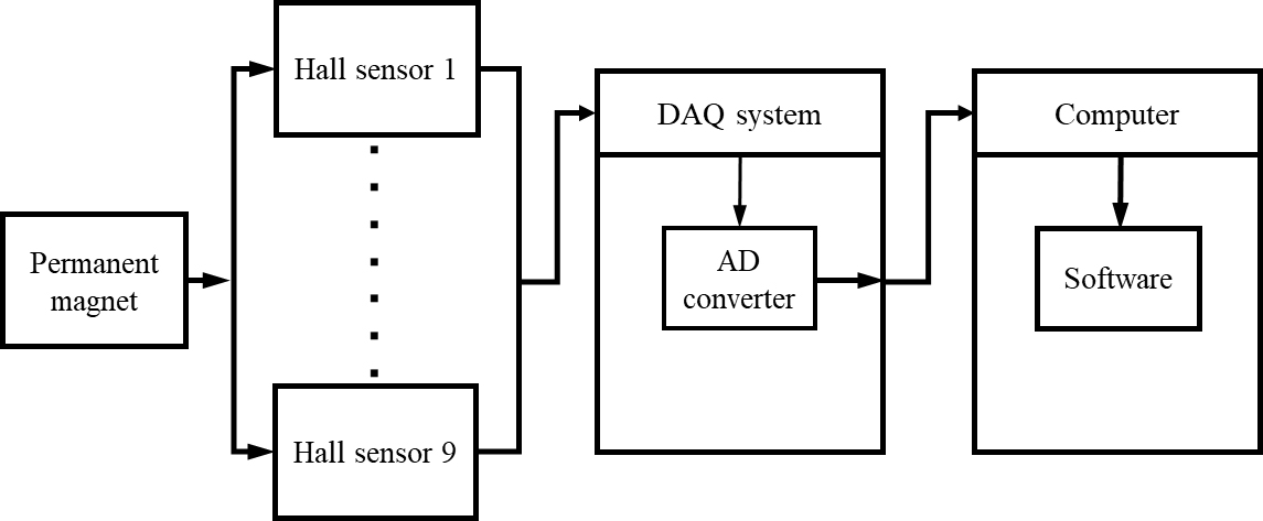
The output of each Hall sensor is measured according to the position of the permanent magnet by the DAQ system USB-6212 (National Instruments, USA). The measured analog output value is converted to its digital form using an AD converter in the DAQ system. The converted digital data is then transferred to a computer, and the position of the permanent magnet is estimated through the position detection algorithm, which is developed in LabVIEW (National Instruments, USA) software.
In the proposed system, a linear Hall sensor WSH138 (Winson, Taiwan) was used in consideration of the characteristic that the output value of the sensor changes according to the position of the permanent magnet in three-dimensional space. The sensor has a sensitivity of 8.7 mV per gauss and an output voltage between 0 and 5 V in the
We designed and fabricated an experimental apparatus to precisely position the permanent magnets. The fabricated apparatus consisted of a bottom surface, sensor fixture, column for fixing the bottom surface, and permanent magnet fixture. The bottom surface was perforated with 25 holes to fix the permanent magnets at 10 mm intervals in both the x and y axis directions, and the design allowed fixing of column by changing the angle by 30 degrees. The designed sensor fixture allowed the Hall sensors to be fixed in the x, y, and z axis directions at each vertex, and the magnet fixture was designed for various heights at intervals of 10 mm in the z axis direction. Aluminum was used as the material of the experimental apparatus as it does not affect the magnetic field.
2.2Proposed position detection algorithm
The proposed position detection algorithm estimates the distance between the permanent magnet and sensor using the intensity of the magnetic field measured by the Hall sensors. The estimated distance depends on the distance and angle between the permanent magnet and Hall sensor. Using the distance between three or more sensors and the permanent magnet, the solution of the spherical equation is obtained, and the three-dimensional position is estimated.
In order to obtain the data, the proposed system obtains measurements from 125 location points of the permanent magnet within the coordinates (1, 1, 1) to (5, 5, 5). The measured data is the intensity of the magnetic field on the Hall sensors arranged in the x, y, and z axis directions at each vertex. First, the output value is measured when the Hall sensor is not influenced by the magnetic field of the permanent magnet; in the case of an ideal Hall sensor, the output values when not influenced by the magnetic field would be the same. However, an error of the initial output value occurs in the case of the practical Hall sensor. The measured values are calibrated by subtracting the value that is not affected by the magnetic field. Further, the calibrated values are considered as absolute values so that only the magnitude of the magnetic field applied to the Hall sensor is obtained without information regarding the pole of the permanent magnet. The intensity of the magnetic field is measured by rotating through 360 degrees at angular intervals of 30 degrees around the z axis on the x-y plane at each point. Thus, the intensity of the magnetic field is measured at each coordinate point. The algorithm of the proposed position detection scheme is shown in Fig. 2a, and the corresponding LabVIEW program interface is shown in Fig. 2b.
Figure 2.
Proposed position detection algorithm; (a) flowchart of the proposed algorithm and (b) designed software for the algorithm using LabVIEW.
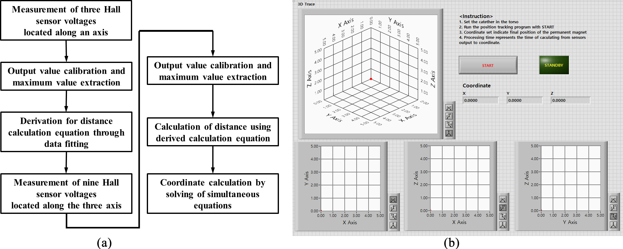
The proposed position detection algorithm is based on the distance calculation equation between the permanent magnet and sensor. The equation is derived from fitting data using Datafit 9.1 (Oakdale Engineering, USA) and by calculating the maximum output value at each point as well as the distances between the permanent magnet and vertex for all 125 coordinates in the three-dimensional space (1, 1, 1) to (5, 5, 5). After deriving the equation, when the permanent magnet is located at an arbitrary position in the three-dimensional space, the output value is obtained from nine Hall sensors that are located at the three vertexes. These values are input to the DAQ system and after AD conversion, the data is transferred to the computer. Through the data processing program implemented in LabVIEW, the maximum output value at each vertex is extracted and substituted into the derived equation to obtain the distances between the permanent magnet and the three vertexes. Thereafter, the position of the permanent magnet is calculated by solving the simultaneous equations for the distances between the three vertexes and the permanent magnet, and the distance values used are calculated from the derived equation. The simultaneous equations used are shown in Eqs (1) to (3).
(1)
(2)
(3)
In Eqs (1) to (3),
3.Experiment and results
3.1Proposed position detection system implementation
To verify the feasibility of the position detection system, an experimental apparatus was constructed and tested. The experimental setup for the verification of the proposed position detection system is shown in Fig. 3.
Figure 3.
Experimental environment for the verification of the proposed position detection system.
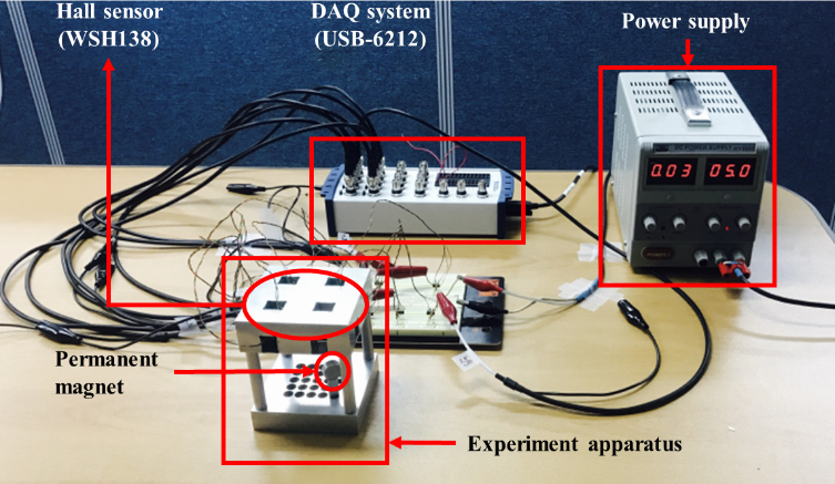
In the experiment, nine Hall sensors were affixed to the x, y, and z axes at three vertexes each in the experimental apparatus. The analog signal output from a 5.0 V input to the Hall sensor is applied to the DAQ system. The input signal is converted into a digital signal by the AD converter and transmitted to a computer. The transmitted data are detected by the data processing program implemented in LabVIEW and the position and distance of the permanent magnet are calculated.
3.2Distance between permanent magnet and Hall sensor
In order to derive the equation for the distance between the permanent magnets and Hall sensor, experiments were conducted; the permanent magnets were placed at 125 points in the range of (1, 1, 1) to (5, 5, 5), and output values were obtained from three Hall sensors in the x, y, and z axes. Thus, a total of 4500 values were obtained and calibrated to derive the distance calculation equation using Datafit.9.1 (Eq. (4)). The acquired constants and error values for Eq. (4) are shown in Table 1.
(4)
Table 1
Acquired constants and standard error values from data fitting
| Variable | Values | Standard error |
|---|---|---|
| a | 2.19550246603738 | 0.156527617152333 |
| b | 0.238274204048772 | |
| c | 0.191639355535731 | |
| d | 0.282576431319038 | |
| e | 0.125883149183374 | |
| f | 1.73157557680492E-02 |
The distances between the permanent magnets and the Hall sensors are then estimated by substituting the output values of the Hall sensor into the derived Eq. (4).
Experiments were conducted to assess the accuracy of the derived distance equation. When a permanent magnet was placed at an arbitrary point in the range of (1, 1, 1) to (5, 5, 5) in three-dimensional space, measurements were obtained from the Hall sensors placed at the three vertexes. Then, the measured values were substituted into Eq. (4) to calculate the distances between the magnet and sensor at each vertex. The experiments were performed for all 125 coordinates, and some of the results comparing the calculated and actual distance values are shown in Table 2.
Table 2
Distance between the magnet and three vertices for the selected measurements
| Position | (0, 0, 0) | (0, 6, 0) | (6, 0, 0) | ||||||
|---|---|---|---|---|---|---|---|---|---|
| Real distance (mm) | Calculated distance (mm) | Error (mm) | Real distance (mm) | Calculated distance (mm) | Error (mm) | Real distance (mm) | Calculated distance (mm) | Error (mm) | |
| (5, 3, 2) | 50.99 | 51.09 | 0.10 | 24.49 | 24.01 | 0.48 | 50.99 | 51.46 | 0.47 |
| (1, 4, 2) | 36.05 | 33.65 | 2.40 | 57.44 | 55.30 | 2.14 | 17.32 | 20.64 | 3.32 |
| (3, 3, 3) | 41.23 | 41.12 | 0.11 | 41.23 | 40.70 | 0.53 | 41.23 | 41.07 | 0.16 |
| (2, 5, 4) | 53.85 | 56.46 | 2.61 | 64.03 | 60.56 | 3.47 | 33.16 | 40.29 | 7.13 |
| (2, 1, 2) | 17.32 | 18.47 | 1.15 | 36.05 | 33.03 | 3.02 | 45.82 | 47.75 | 1.93 |
The mean error in distance was 2.82 mm at (0, 0, 0), 2.73 mm at (0, 6, 0), and 2.73 mm at (6, 0, 0). The average error of the three vertexes was 2.76 mm, and the accuracy of Eq. (4) was thus verified.
3.3Detecting position of permanent magnet
In order to calculate the positions of the permanent magnet, the distances were calculated using Eq. (4). Then, the calculated distances are assigned to simultaneous Eqs (1) to (3). Experiments were performed for all 125 coordinates, and some of the positions of the permanent magnet calculated from the simultaneous Eqs (1) to (3) and the distances from the origin (0, 0, 0) are shown in Table 3.
Table 3
The magnet’s position value and distance calculation value for the selected measurements
| Real value | Calculated value | Error | |||||||||
|---|---|---|---|---|---|---|---|---|---|---|---|
| X | Y | Z | Distance (mm) | X | Y | Z | Distance (mm) | X | Y | Z | Distance (mm) |
| 5 | 3 | 2 | 61.64 | 4.69 | 2.96 | 2.17 | 59.55 | 0.31 | 0.04 | 0.17 | 2.09 |
| 1 | 4 | 2 | 45.82 | 1.39 | 3.58 | 1.87 | 42.71 | 0.39 | 0.42 | 0.13 | 3.11 |
| 3 | 3 | 3 | 51.96 | 3.02 | 3.00 | 1.13 | 44.04 | 0.02 | 0.00 | 1.87 | 7.92 |
| 2 | 5 | 4 | 67.08 | 2.60 | 4.30 | 2.56 | 56.39 | 0.60 | 0.70 | 1.44 | 10.69 |
| 2 | 1 | 2 | 30.00 | 2.37 | 1.38 | 2.03 | 34.12 | 0.37 | 0.38 | 0.03 | 4.12 |
Using the measured data, the mean errors of the calculated positions are 7.35 mm for the x axis, 12.52 mm for the y axis, and 16.96 mm for the z axis when compared to the actual positions; moreover, the calculated distance from the origin to the permanent magnet position has an average error of 3.11 mm.
4.Conclusion
In this study, a 3D position detection system for a medical simulator was developed. The proposed system has advantages such as utilizing a relatively simple algorithm, small amount of computation, and high efficiency in terms of cost of system configuration. Further, it does not emit radiation and therefore does not cause harmful exposure. According to the experimental results, the mean error of the distance between the permanent magnet and the vertexes calculated from the derived distance equation was 2.76 mm; moreover, the derived position value has a mean error of 7.35 mm for the x axis, 12.52 mm for the y axis, and 16.96 mm for the z axis. In addition, the mean error of the distance between the calculated position of the permanent magnet and the origin (0, 0, 0) was 3.11 mm. From the experimental results, the proposed system shows high error compared to the other studies. The cause of this high error value is the generated electromagnetic noise in the process of measuring the outputs and the derived equation using the data fitting program. Another cause might be errors due to the z axis positioning, which can be measured only in one direction, unlike the x and y axes, which can be measured in multiple directions through sensors located on three sides.
In the future, considering the scope for extension, it is possible to detect the position in a wider range of three-dimensional space through additional arrangement of Hall sensors; further, we expect to carry out research on methods to increase the accuracy without increasing the complexity of the proposed system. Furthermore, if the position errors in the three-dimensional space can be reduced, it is expected that the proposed system can be used not only in medical simulators but also in actual surgical situations by sensitivity improvement and placement of the Hall sensor.
Acknowledgments
This research was supported by a grant from the Korea Health Technology R&D Project through the Korea Health Industry Development Institute (KHIDI), funded by the Ministry of Health & Welfare, Republic of Korea (grant no.: HI17C2594) and by the National Research Foundation of Korea (NRF) grant funded by the Korean government (MSIP) (grant no. NRF-2019R1A2C2004347).
Conflict of interest
None to report.
References
[1] | Shin AS, Lim SY, Sung JH, Shin HR, Kim JS. Dietary intake, eating habits, and metabolic syndrime in Korean Men. Journal of the AMERICAN DIETETIC ASSOCIATION. (2009) ; 109: (4): 633640. |
[2] | NIA, Informatization Planning Team; Ubiquitous Society Medical and Health Business Trend. (2006) ; 17. |
[3] | Cause of Death Statics [homepage on the Internet]. Statistics Korea; 2019 [updated 2015 March 12; cited 2019 March 12]. Available from: www.kosis.kr. |
[4] | Moon YJ, Choi JS. An Intuitive Teleoperation Method for Cardiovascular Intervention Assist Robot. Proceeding of the Fall Conference of the Institute of Control, Robotics and Systems. (2016) ; pp. 203-204. |
[5] | Jena AB, Seabury S, Lakdawalla D, Chandra A. Malpractice risk according to physician specialty. Journal of the New England Journal of Medicine. (2011) ; 367: (7): 629-636. |
[6] | Kim SH, Lee JW, Kim JH, Lee HW, Jung WG, Lee GK. Insertion path extraction of catheter for coronary angiography. Journal of the Korea Institute of Information and Communication Engineering. (2011) ; 15: (4): 951-956. |
[7] | Cooper JB, Taqueti VR. A brief history of the development of mannequin simulator for clinical education and training. Journal of Quality and Safety Health Care. (2004) ; 13: (1): 111-118. |
[8] | Ahn BM, Jung EY, Lee YH, Lim YS, Park RW, Kim J, et al. Needle insertion force of biological soft tissue for haptic based intravenous injection simulator. Journal of the Korean Society for Precision Engineering. (2012) ; 29: (2): 222-228. |
[9] | Koo YJ, Choi HY, Ahn WJ, Lee DY. Haptic Device for Catheter Simulation. Proceeding of the Fall Conference of the institute of Control, Robotics and Systems. (2008) ; pp. 444-446. |
[10] | Moon YJ, Choi JS. Development of Master Device for Catheter Tip Control of Robotic Cardiovascular Catheterization Intervention System Staun. Proceeding of the Fall Conference of the Korean Society for Precision Engineering. (2015) ; 62-63. |
[11] | Jayender J, Patel RV, Nikumb S. Robot-assisted active catheter insertion: algorithms and experiments. Journal of The International Robotics Research. (2009) ; 28: (9): 1101-1117. |
[12] | Cabral G, Amaral A, Campos L, Guimaraes MI. Investigation of maximum doses absorbed by people accompanying patients in nuclear medicine departments. Journal of Radiation Protection Dosimetry. (2002) ; 101: (1): 435-438. |
[13] | Weitschies W, Karaus M, Cordini D, Trahms L, Breikreutz J, Semmler W. Magnetic marker monitoring of disintegrating capsules. European Journal of Pharmaceutical Sciences. (2001) ; 13: (4): 411-416. |
[14] | Chadil N, Russameesawang A, Keeratiwintakorn P. Real-time Tracking Management System Using GPS, GPRS and Google Earth. Proceeding of the 5th International Conference on ECTI-CON. (2008) ; 1: : 393396. |
[15] | Hoenig HE, Daalmans G, Folberth W, Reichenberger H, Schneider S, Seifert H. Biomagnetic multichannel system with integrated SQUIDS and first order gradiometers operating in a shielded room. Cryogenics. (1989) ; 29: : 809-813. |
[16] | Kim SH, Park KS. A study on navigation sensor system for outdoor AGV using AMR sensors. Journal of Control, Automation, and Systems Engineering. (2003) ; 9: (2): 140-144. |
[17] | Choi HY, Lee HI. Design of anisotropic magnetoresistance sensor module for vehicle detection. Journal of the Korean Institute of Illuminating and Electrical Installation Engineers. (2011) ; 25: (8): 99-105. |
[18] | Kim EJ, Kim ES, Lim YC. Magnet position sensor system using hall sensors. Journal of the Korean Entertainment Industry Association. (2011) ; 5: (2): 166-172. |
[19] | Hu C, Li M, Song S, Yang W, Zhang R, Meng MQH. A cubic 3-axis magnetic sensor array for wirelessly tracking magnet position and orientation. Journal of the Institute of Electrical and Electronics Engineers Sensors. (2010) ; 10: (5): 903-913. |


