
Development of an actuation system to apply hydrogen storage alloy for the rehabilitative system
Abstract
BACKGROUND:
Hydrogen has advantages that can be used as energy, but research on safe use is needed.
OBJECTIVE:
In this study, an actuation system for rehabilitation is developed to drive the actuator using hydrogen storage alloy and to analyze the hydrogen release characteristics of the alloy.
METHODS:
The system is automatically control and report the pressure, temperature and hydrogen flow using LabVIEW-based modules and LabVIEW software. Zr
RESULTS:
The loads of 5 and 10 kg were raised by 87 and 19 mm at 70
CONCLUSIONS:
The actuation system in this paper can be applied to assistive device and rehabilitation system for assisting the movement of daily life of the elderly or people with disability.
1.Introduction
Hydrogen has much advantages as future energy. However, since hydrogen is a highly flammable material, continuous research on various technologies to safely storage and utilize hydrogen is needed. Using the hydrogen storage alloy has the advantage that the hydrogen storage alloy can compress 1000 times the initial volume safely and stored it at a very high density compared to the liquid or gaseous hydrogen storage methods. It can also be used by releasing the stored hydrogen adjusting the temperature and pressure. Using hydrogen storage alloys with these characteristics has attracted attention as this technology can be used in mobile distributed power sources due to the low operating pressure compared to other storage methods and has high consumer acceptance when used indoors [1, 2, 3]. The studies using hydrogen storage alloy as a driving source are outlined below.
Madaria used La
Ino used carbon fiber, aramid pulp, and LaNi
The actuation system using hydrogen storage alloy has been applied to the development of rehabilitation system for the daily life of the elderly because of the high power of the compact device. Hosono et al. measured lower-extremity blood flow during passive motion of the toe to design new rehabilitation equipment which is applying the soft MH actuator to toe joints for the purpose of preventing disuse syndrome, contractures, edema and bedsores [10, 11]. Ino developed CPM machine for a finger joint using metal hydride actuator that includes a small metal bellows [12]. Ino and Sato designed an elbow CPM machine using a pair of metal or laminate film bellows [13]. Existing rehabilitation systems using hydrogen storage alloys use only mechanical movements due to the movement of hydrogen gas, but studies on measuring the exact flow rate of hydrogen are insufficient. Accurate flow measurement of hydrogen is necessary to assist the daily life of the elderly and the disabled. In this study, an actuation system for rehabilitative system was developed to drive the actuator using hydrogen storage alloy and to analyze the hydrogen release characteristics of the alloy.
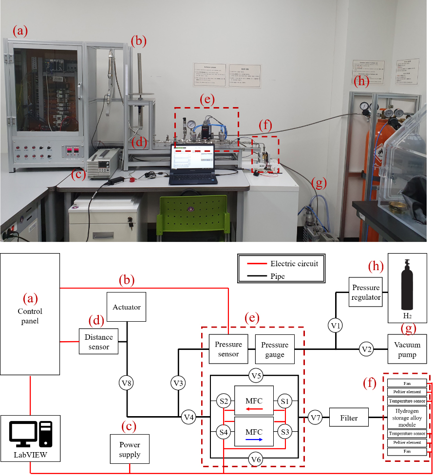
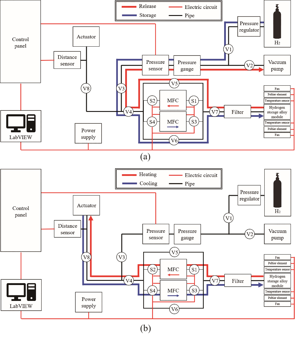
Figure 1.
Hydrogen storage alloy actuation system and block diagram of whole system; (a) Control panel, (b) Actuator, (c) Power supply, (d) Distance sensor, (e) Pressure and flow control part, (f) Hydrogen storage alloy module, (g) Vacuum pump, (h) Pressure regulator and hydrogen bomb.
2.System configuration
2.1Actuation system
In this study, hydrogen was desorbed and absorbed by heating and cooling by two of peltier elements in the hydrogen storage alloy module with hydrogen storage alloy, whose performance was evaluated by the actuator. Figure 1 shows the block diagram of the hydrogen storage alloy actuation system. V1-8 and S1-4 are the valves to regulate the flow of hydrogen, and S1-4 is a pneumatic solenoid valve that can be automatically opened and closed using nitrogen. As the flow direction of hydrogen changes, pneumatic valves are used to accurately check and integrate the flow rates for each heating and cooling state. Figure 1a is Control panel, which contains several modules and control PCBs, and system controlled by LabVIEW program. Figure 1b is actuator, and the diameter of actuator (TPC Mechtronics Corp., Korea) is 32 mm, and strokes is 150 mm. Power supply was used PSW 80-27 (GW Instek, Taiwan) (Fig. 1c). Distance sensor was used US18-PA-5-NO3-VH (Datalogic, Italy) (Fig. 1d). Figure 1e is “Pressure and flow control part,” and Fig. 1f is “Hydrogen storage alloy module”. Vacuum pump was installed with GHP-150K (Kodivac, Korea) and pressure regulator was used YR-5061 (Yamato Sangyo Co. Ltd., Japan) (Fig. 1g and h).
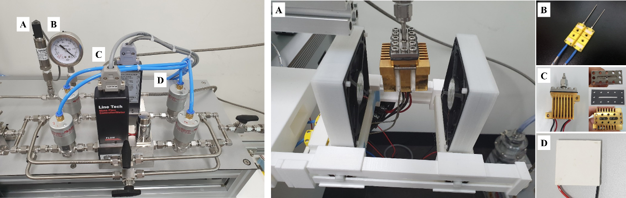
Figure 2.
(a) Pressure and flow control part; A-Pressure sensor, B-Pressure gauge, C-Mass flow controller (MFC), D-Pneumatic solenoid valves; (b) Hydrogen storage alloy module; A-Hydrogen storage alloy module part, B-Temperature sensor, C-Hydrogen storage module, D-Peltier elements.
2.2Pressure and flow control
Figure 2a is ‘Pressure and flow control part’. Two different mass flow controllers can be used to control the amount of hydrogen entering the hydrogen storage alloy and the amount of hydrogen flowing out of the hydrogen storage alloy. A pressure sensor (OMEGA, USA) and a pressure gauge (SIGMA Tech, Korea) were used to continuously check the pressure inside the system. Two different MFCs (Linetech, Korea) and four pneumatic solenoid valves (Hy-Lok, Korea) were used to control the amount of hydrogen entering and flowing out of the hydrogen storage alloy.
2.3Hydrogen storage alloy module
Figure 2b shows the hydrogen storage alloy module part. In hydrogen storage alloy module part, two temperature sensors (OMEGA, USA) check and control the temperature of the module and peltier elements (Wellen, China) change temperature of the module. The module consisted of module cover, sealing pad, peltier elements and power charging unit which is made of copper. The module cover distributes hydrogen gas in the two holes of hydrogen storage alloy power charging part. Sealing pad was made of 1 mm thick of teflon to prevent gas leakage. Besides, a hydrogen channel was inserted in order to shorten the activation time and increase the efficiency of hydrogen storage alloy. When the peltier element heats the module, hydrogen is released from the alloy in the module. Subsequently, when the peltier element and Fan cools the module, hydrogen is absorbed back into the alloy.
2.4System control program using LabVIEW
Figure 3a is a block diagram of the VIs placed to control the system by selecting either control mode or auto mode. In control mode, power, heating/cooling mode, fans, solenoid valves can be turned on/off by the button on the front panel. In auto mode, it is designed to automatically control the entire system according to each condition by selecting either time mode or temperature mode. When the heating/cooling mode is changed, the direction of the DC voltage is reversed and it reverse a heating/cooling function of the peltier element in the hydrogen storage alloy module as shown in Table 1. Figure 3b is a block diagram created using the DAQ of digital output module (NI 9472), which controls on/off power and fans, heating/cooling mode switching, and opening/closing of the solenoid valves when in control mode. In this study, NI 9427 was used to turn on/off or change the applied mode of the connected device.
Table 1
Automatic change of device setting by changing mode (heating/cooling)
| Mode | Power | Voltage | Fans | Solenoid valves | ||||
|---|---|---|---|---|---|---|---|---|
| Sol 1 | Sol 2 | Sol 3 | Sol 4 | |||||
| Auto mode | Heating | On | Forward | Off | On | On | Off | Off |
| Cooling | Reverse | On | Off | Off | On | On | ||
Figure 3.
(a) Block diagram for auto controlling all the functions, (b) Controlling power and fans on/off, heating/cooling mode change and solenoid valves open/close, (c) Block diagram of saving sensor values automatically, (d) Sensing values of pressure, load, and flow change, (e) Sensing value of the temperature change, (f) Block diagram of saving sensor values automatically.
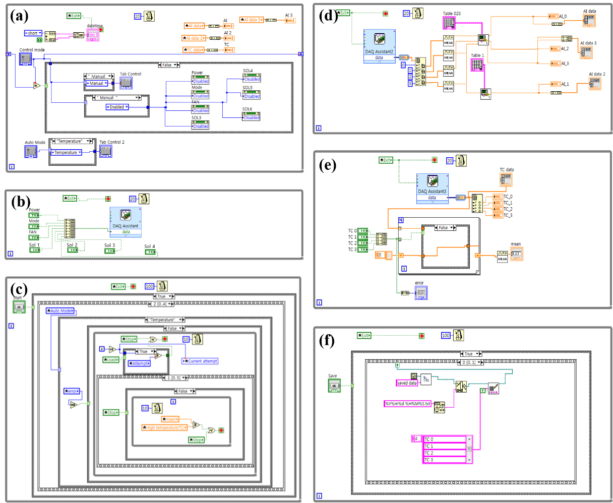
Figure 3c shows a block diagram that can control the system according to time/temperature mode when in auto mode. In time mode, heating and cooling times can be set, and in temperature mode, high and low temperatures can be set. The heating/cooling mode is automatically changed if the average temperature, reaches high or low temperatures. Figure 3d shows a block diagram created using the DAQ of an analog input module (NI 9221). Through this block diagram, graphs of the values detected from the pressure sensor, load cell, and MFC are displayed on the front panel. Figure 3e shows a block diagram created using the DAQ of a temperature input module (NI 9211). The values sensed from a temperature sensor is sent by NI 9211. The average of the selected values from the measured temperature is displayed on the front panel. Figure 3f is a block diagram of the VIs placed to automatically save the measured sensor values in the Notepad program.
3.Material characterization
3.1Preparation of the hydrogen storage alloy
Zr
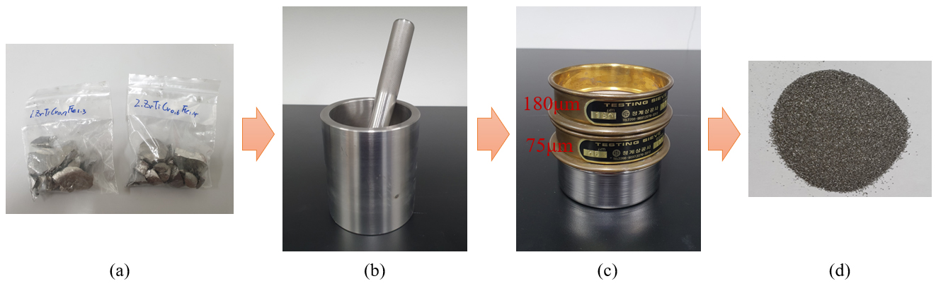
Figure 4.
Powdering stage of the hydrogen storage alloy; (a) Hydrogen storage alloy, (b) Grinding, (c) 75 and 180 sieves, (d) Hydrogen storage alloy powder.
3.2Characteristics analysis
3.2.1HRXRD (high-resolution X-ray diffraction)
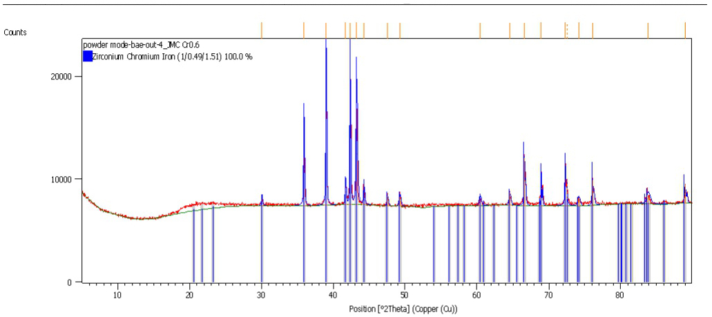
In this study, HRXRD (Empyrean, Malvern Panalytical, England) analysis was performed to determine if Zr
Table 2
Crystallographic parameters of Zr
| a (Å) | b (Å) | c (Å) | ||||
|---|---|---|---|---|---|---|
| Zr | 5.0060 | 5.0060 | 8.1930 | 90.0 | 90.0 | 120.0 |
Figure 5.
HRXRD result of Zr
3.2.2FE-SEM (field-emission scanning electron microscope)
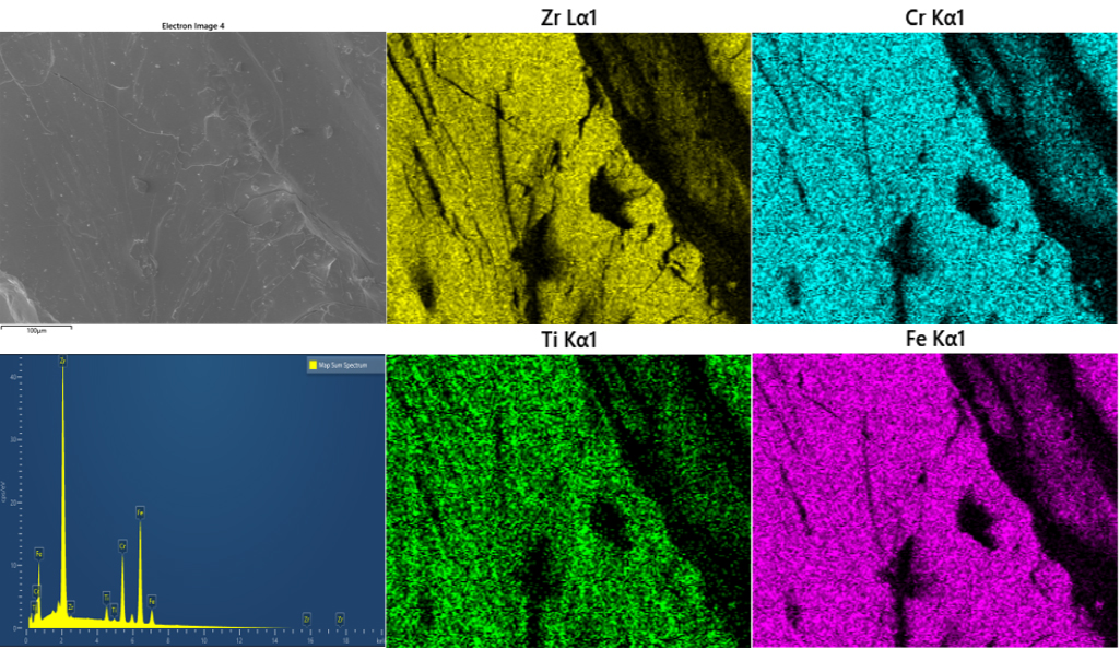
In this study, FE-SEM and EDS mapping were measured to confirm the surface composition of Zr
Table 3
FE-SEM/EDS mapping result of Zr
| Element | Zr | Ti | Cr | Fe | |
|---|---|---|---|---|---|
| 1 | Wt% | 41.01 | 2.43 | 15.95 | 40.61 |
| 2 | Wt% | 40.45 | 2.36 | 16.56 | 40.62 |
| 3 | Wt% | 41.13 | 2.18 | 16.18 | 40.51 |
| 4 | Wt% | 38.64 | 2.44 | 16.82 | 42.09 |
| Average | Wt% | 40.73 | 2.40 | 16.37 | 40.62 |
Table 4
Difference between average measurement value (wt%) with original value (wt%)
| Element | Average (%) | Difference (%) | |
| Zr | Zr | 40.73 | 1.10 |
| Ti | 2.40 | 0.04 | |
| Cr | 16.37 | ||
| Fe | 40.62 |
Table 5
ICP-OES analysis result of Zr
| Zr | Ti | Cr | Fe | Sum | |
|---|---|---|---|---|---|
| Average | 41.28% | 2.73% | 17.34% | 43.53% | 104.88% |
| 1 | 40.50% | 2.72% | 17.37% | 43.78% | 104.37% |
| 2 | 41.83% | 2.72% | 17.32% | 43.36% | 105.23% |
| 3 | 41.52% | 2.74% | 17.32% | 43.45% | 105.03% |
Figure 6.
FE-SEM and EDS mapping of Zr
3.2.3ICP-OES (inductively coupled plasma optical emission spectrometry)
In this study, ICP-OES was performed to analyze the quantitative determination of Zr
3.2.4Hydrogen absorption kinetics
Hydrogen absorption kinetics is a measure of the amount of hydrogen adsorbed by a hydrogen storage alloy at a certain pressure. The process of removing vacuum gas for 3 min at room temperature, introducing hydrogen gas of 1 MPa and maintaining for 1 min was repeated five times. This is a process for replacing the alloy with hydrogen gas. After that, the activation process was started. After vacuum degassing at room temperature for about 30 to 60 min, high pressure hydrogen was added to the sample and left until there was no pressure drop in the system. The vacuum gas removal treatment herein refers to a process for decomposing the metal hydride phase and returning it to the metal phase (hydrogen solid solution phase) by maintaining the pressure of the sample container at 1 kPa or less for several minutes. Thereafter, the reaction rate was repeatedly absorbed and desorbed at a temperature to measure the amount of hydrogen storage to speed up the reaction rate and stabilize the absorption and desorption properties. As a method for measuring the amount of hydrogen storage, vacuum origin was used. This is a method of absorbing hydrogen at the pressure to be measured to the activated sample and leaving it until the pressure inside the system shows an equilibrium value. The amount of hydrogen storage is obtained by calculating the percentage change in the weight percentage of the alloy (wt%) or the atomic ratio and the amount of change between the hydrogen and the alloy. In this study, the hydrogen storage in 4 MPa was measured using activated Zr
4.Actuation test
The activation treatment involved removal of oxides formed inside the powdered hydrogen storage alloy and solid-state storage of hydrogen on the hydrogen storage alloy loaded inside the module, so that hydrogen could be desorbed from the hydrogen storage alloy when heat was applied [14]. The hydrogen storage alloy was activated under 5 MPa pressure of hydrogen gas (room temperature was 19–21
Figure 7.
Movement of hydrogen in hydrogen storage alloy system: (a) Activation process, (b) Actuation test.
5.Results and discussion
The activation of Zr
Figure 8.
Curve of hydrogen absorption kinetics of Zr
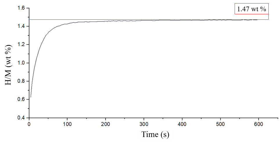
Figure 9.
Hydrogen releasing and absorbing.
Before start actuation test, hydrogen releasing and absorbing test was conducted. The hydrogen storage alloy module was heated by 80
Table 6
Pressure and Lifting force change by load
| 5 kg | 10 kg | 15 kg | 20 kg | |
|---|---|---|---|---|
| Pressure (MPa) | 0.125 | 0.175 | 0.235 | 0.315 |
| Lifting force (kgf) | 100.531 | 140.743 | 188.998 | 253.338 |
Table 7
Results of the actuation test
| Temperature ( | Load (kg) | Stroke (mm) | Lifting time (s) |
|---|---|---|---|
| 70 | 5 | 87 | 1,200 |
| 10 | 19 | 1,436 | |
| 15 | – | – | |
| 20 | – | – | |
| 75 | 5 | 131 | 130 |
| 10 | 70 | 200 | |
| 15 | 15 | 348 | |
| 20 | – | – | |
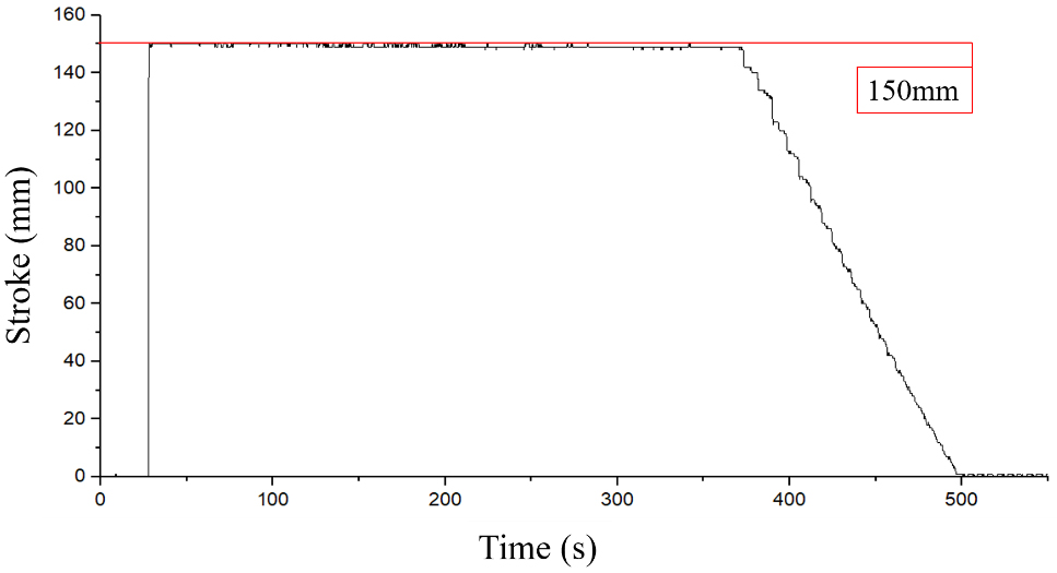
| 80 | 5 | 150 (Max.) | 373 |
| 10 | 83 | 397 | |
| 15 | 55 | 635 | |
| 20 | 28 | 755 |
Result of the stroke changing was measured after piston stopped completely. The results are shown in Table 7. As the results, the loads of 5 and 10 kg were raised by 87 and 19 mm at 70
However, this result is inconsistent with the PCT analysis in advanced research, which was referred to when selecting the alloy. In advanced research, Zr
6.Conclusion
In this study, a new actuation system of automatic type that can be driven by hydrogen storage alloy were developed and release experiments were also conducted. Performance of system using hydrogen storage alloy was upgraded than existing system to automatically control and measure the hydrogen flow. This is a very important issue in the development of rehabilitation devices where user safety is important. It is also expected that this system will be applied to the development of devices that use hydrogen storage alloys as hydrogen storage sources in the future. Through the experiment, the actual driving performance of the new actuation system was confirmed. In addition, it was confirmed that the hydrogen pressure that the hydrogen storage alloy can release increases with increased applied temperature. In future studies, it is necessary to conduct research for improving the quality of the alloy and miniaturizing the system. The actuation system in this paper can be applied to assistive device and rehabilitation system for assisting the movement of daily life of the elderly or people with disability. It is expected to be used as a rehabilitation device for joints such as fingers, hands and knees of stroke patients or as a driving force for standing aids for disabled people.
Acknowledgments
This study was supported by the Basic Science Research Program through the National Research Foundation of Korea (NRF) funded by the Ministry of Education (2018R1D1A3B07049251).
Conflict of interest
None to report.
References
[1] | Park CS, Kim JW, Bae KK, Jeong SU, Kang KS. Investigation of Thermal Management Parameters of Metal Hydride Based Hydrogen Storage System, Korean Hydrogen and New Energy Society. (2018) ; 29: (3): 251-259. |
[2] | Rusman NAA, Dahari MA. A review on the current progress of metal hydrides material for solid-state hydrogen storage application. Hydrogen Energy. (2016) ; 26: : 12108-12126. |
[3] | Lototskyy MV, Tolj I, Pichering L, Sita C, Barbia F, Yartys V. The use of metal hydrides in fuel cell applications, Progress in Natural Science: Materials International. (2017) ; 27: (1): 3-20. |
[4] | Madaria Y, Kumar EA. Effect of heat transfer enhancement on the performance of metal hydride based hydrogen compressor. International Journal of Hydrogen Energy. (2016) ; 41: : 3961-3973. |
[5] | Obara S, Matsumura K, Aizawa S, Kobayashi H, Hamada Y, Suda T. Development of a solar tracking system of a nonelectric power source by using a metal hydride actuator. Solar Energy. (2017) ; 158: : 1016-1025. |
[6] | Ino S, Sakaki K, Hosono M, Doi K, Shimada S, Chikai M. Application of Metal Hydride Paper to Simple Pressure Generator for Use in Soft Actuator Systems. presented at 37th Annual International Conference of the IEEE Engineering in Medicine and Biology Society (EMBC). Milan. Italy, Aug, 25–29, (2015) . |
[7] | Sato M, Yoshimura S, Hosono M, Yamashita K, Ino S. Development of a new portable rescue tool using metal hydride alloys. International Journal of Engineering Research and Development. (2017) ; 13: (5): 52-58. |
[8] | Jeon WS. SMH Actuator Development and Temperature-Pressure Characteristics Using a Peltier Module. M. S. thesis. Chonbuk National University, (2005) . |
[9] | Yan L. Study on module shape design of metal hydride-based hydrogen storage for medical system. M. S. thesis. Jeonbuk National University, (2018) . |
[10] | Hosono M, Ino S, Sato M, Yamashita K, Izumi T, Ifukube T. Design of a Rehabilitation Device using a Metal Hydride Actuator to Assist Movement of Toe Joints. Presented at Asia International Symposium on Mechatronics 2008. Hokkaido University. Japan, Aug, (2008) . |
[11] | Hosono M, Ino S, Sato M, Yamashita K, Izumi T. A system utilizing metal hydride actuators to achieve passive motion of toe joints for prevention of pressure ulcers: a pilot study. Rehabilitation Research and Practice. (2012) ; 2012: (541383): 1-7. |
[12] | Ino S, Sato M. Soft and Noiseless Actuator Technology Using Metal Hydride Alloys to Support Personal Physical Activity. Assistive Technologies. Dr. Fernando Auat Cheein (Ed.), ISBN: 978-953-51-0348-6, InTech, Available from: http//www.intechopen.com/books/assistive-technologies/soft-and-noiseless-actuator-technology-using-metal-hydride-alloys-to-support-personal-physical-activ. |
[13] | Ino S, Sato M. Human-Centered Metal Hydride Actuator Systems for Rehabilitation and Assistive Technology. In: Handbook of Research on Personal Autonomy Technologies and Disability Informatics. Pereira J. (Ed.), pp. 154-170, IGI Global, ISBN: 978-1-6056-6206-0, Hershey, New York. |
[14] | Kwon TK, Hong KJ, Kim K, Jeon WS, Pang DY, Lee SC, Kim NG. Development of SMH actuator system using hydrogen-absorbing alloy. Journal of Control, Automation and Systems Engineering. (2007) ; 13: (11): 1067-1073. |
[15] | Park JM. A Study on the Hydrogenation Characteristics of Zr-based Laves Phase Intermetallic Compounds. Ph. D. thesis. Korea Advanced Institute of Science and Technology. (1989) . |


