
Development of a low-cost six-axis alignment instrument for flexible 2D and 3D ultrasonic probes
Abstract
BACKGROUND:
The pulse-echo test is used to evaluate the performance of ultrasonic probes before manufacturing ultrasonic systems. However, commercial alignment instruments are very large and use complex programs with long operation times.
OBJECTIVE:
To develop a low-cost alignment instrument used in the pulse-echo test for evaluating the performance of various 2D and 3D ultrasonic probes.
METHODS:
The developed alignment instrument can be aligned with the X, Y, Z, azimuth, elevation, and tilt axes with manual structure to support mounting fixtures that hold 2D and 3D ultrasonic probes. Each axis has a manual lever and is designed to have no movement when fixed. In particular, tilt and azimuth directions are designed to move more than 5
RESULTS:
The probe mounted in the X, Y, and Z axes can move at above 50 mm. The probe mounted in the azimuth, elevation, and tilt axes can move more than 5
CONCLUSIONS:
Our developed alignment instrument can reduce costs by eliminating the need for shortening inspection times for probe manufacturers.
1.Introduction
Ultrasonic (ultrasound) systems have been used for various applications such as automotive ultrasonic sensors, nondestructive testing devices, and medical ultrasonic sensors [1, 2, 3, 4]. Among ultrasound systems, ultrasonic probes are one of the most important devices [5, 6]. However, the manufacturing of ultrasonic probes requires a large number of hands-on fabrication processes [7, 8, 9]. Therefore, systematic checks are very important to monitor the operations of all the elements in ultrasonic probes [10, 11, 12]. The pulse-echo test has been utilized to evaluate the performances of the ultrasonic probe before being integrated into ultrasonic systems [7, 13, 14, 15]. Ultrasonic probe production includes various inspection processes [16, 17]. Among these is the pulse-echo test, which is one of the fundamental testing methods [2, 18, 19]. The pulse-echo test is also a fundamental test for ultrasonic probe repairs such as sensor breakdown and incorrect wiring inside the piezoelectric materials of ultrasonic probes [16, 20]. An alignment instrument with a water tank system is the basic component of the pulse-echo test as the aligned ultrasonic probes need to be immersed in the water tank [21, 22, 23, 24]. In the pulse-echo test, the transmitting and receiving probes are used to obtain the transmitting and receiving ultrasonic waves properly [25, 26]. The alignment of the probes and target is required for the inspection of ultrasonic probes [27, 28]. Different types of probes are for different organs such as heart, stomach, colon, and small intestine [29, 30, 31, 32].
The pulse-echo test has been conducted using commercial alignment instruments with complex motion control boxes [24, 25, 33]. Because the support structures of complex motion control boxes in commercial alignment instruments are very large and require complex program setup with long operating times, the development and inspection of ultrasonic probes are difficult [16]. In addition, different types of fixtures are needed to hold and support different types of probes. The developed alignment instrument can be easily and conveniently aligned with a six-axes manual structure to support the mounting fixtures that hold 2D ultrasonic probes such as linear and convex probes as well as 3D ultrasonic probes. Moreover, the compact size of the developed instrument makes it easy to transport unlike conventional commercial alignment instruments.
2.Materials and methods
Figure 1 shows the design of the fixtures for travelling along the X, Y, Z, azimuth, elevation, and tilt axes. The traveling range along the X, Y, and Z axes is
Figure 1.
X, Y, Z, azimuth, elevation, and tilt directions of the (a) probes and (b) fixtures in the alignment instrument.
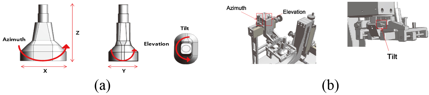
To manufacture the six-axis alignment instrument, the fixed-axis devices that can move in the vertical and horizontal directions must be mounted on the ultrasonic probe. The angle-shifting device must tilt the probe, and the device must move the azimuth and elevation angles. In the case of vertical movement, the target can be moved up and down with azimuth angles and the probe can be moved in the elevation direction. Each axis uses a manual lever and is designed to have no movement when fixed. The tilt and azimuth directions are designed to move more than 5
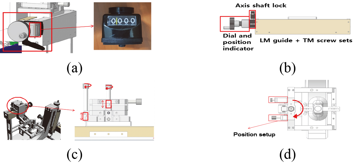
Figure 2a shows the indicators for operating the X, Y, and Z axes and how the right positions can be found using the manual dial. As the indicators were set with the ball screw pitch, we can confirm the exact moving distance. As shown in Fig. 2b, in the X, Y, and Z axes, the dial and position indicators with linear motion (LM) guide and trapezoidal metric (TM) screw sets have the same structures. In Fig. 2c, rotating the bolt part raises or lowers the shaft part. Rotating the LM guide in the direction indicated in Fig. 2d allows the entire structure to rotate with the lower shaft portion that moves forward and backward.
Figure 2.
(a) Indicators for X, Y, and Z-axis, (b) dial and position indicators with LM guide and TM screw sets, (c) shaft part movement, and (d) position setup.
The target axis has a structure in which X and Z axes can move. Therefore, the six axes supporting the X, Y, Z, tilt, azimuth, and elevation direction and the fixtures for mounting various probes such as 2D linear and convex as well as 3D-type probes were installed. Recently, rounded/curved 3D probes have been widely used; hence, fixtures need to be designed to fix three probe types for mounting. Figure 3 shows the 2D probe holders for linear and convex probes and 3D probe holders for 3D probes.
Figure 3.
(a) 2D and (b) 3D probe holders.
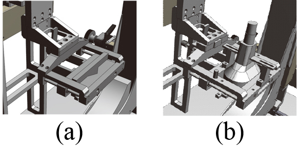
Figure 4.
(a) 2D probe insertion position, V-cut, and (b) 3D probe insertion holder with modeled 3D probe.
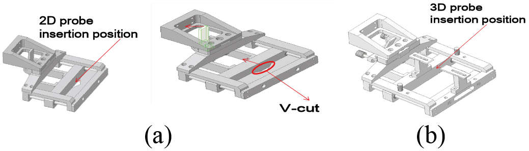
Figure 4 shows the probe holder operations. In Fig. 4a, the V-cut was used to securely hold 2D curved probes. When the displayed lever is snapped back, the probe-fixing frame moves back with it. When the lever is released using the spring, the fixing frame of the probe fixes the probe by the spring forces. Figure 4b shows how the 3D ultrasonic probe is held in the structure. The fixing method is the same as that of the 2D probe. However, because 3D probes are larger than 2D probes, they are also firmly fixed by supporting structures in the lower and upper fixing frames as shown in Fig. 4b.
Figure 5.
(a) X and Z-axis support; (b) Y-axis support; (c) front and (c) side-views of the water tank with alignment instruments.
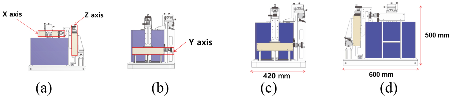
As shown in Fig. 5, in water tank the lens of the ultrasonic probes were attached to the fixed device can be submerged with 80% water filled inside the water tank based on the underwater condition similar to human temperature [34]. The specifications of the water tank are as follows. The width, depth, height, and thickness of the water tank are 400, 300, and 300 mm, and 1 cm (10 T), respectively. The water tank is made of transparent material so that the interior can be checked for alignment. The acrylic water tank was welded to prevent leakage. A stainless steel reflector was manufactured to transmit (Tx) and receive (Rx) ultrasonic waves and minimize wave deformation; a structure for mounting the reflector in the water tank was also manufactured [28, 35]. Figure 5 shows the location of the X, Y, and Z axes as well as the dimensions of the front and side of the water tank with the alignment instrument.
3.Results and discussion
As the pulse-echo test examines the characteristics of entire probe channels, the probes need to be aligned with the reflector in the instrument [32, 36]. The distance between the reflector and probe must be maintained to accurately characterize each channel [37, 38]. Therefore, it was concluded that the stator must be configured for moving for moving the intake axis of the reflector along the straight line of the X, Y, Z axes and the rotation axis of the azimuth, tilt, and elevation axes. The linear movement can be included in the structural design so that the movement distance can be confirmed by mounting the position indicator. Figure 6a and b show the waterproofing test for the water tank. More than 70% of the human body is water; hence, the lenses of the ultrasonic probes should be submerged [39]. The test for water tank leakage was conducted for approximately 10 min using a timer and it was confirmed that there was no water leakage. Figure 6c shows the drain lever of the water tank to drain contaminated water.
Figure 6.
(a) Start and (b) end time of the water tank leakage test with smartphone timer; (c) the drain lever of the water tank.
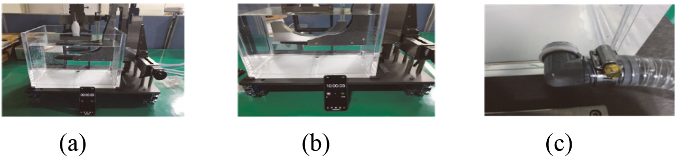
Figure 7.
Mounting position for (a) 2D (b) 3D ultrasonic probes.
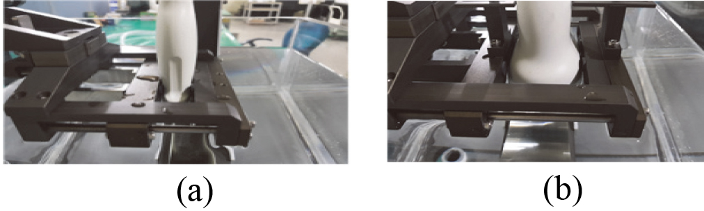
Figure 7 shows the mounting positions of the 2D and 3D-type ultrasonic probes on the alignment instrument. The probe must remain fixed when the axis of the instrument mounting the linear and convex-type probes moves. Therefore, the spring can be used to firmly hold the probe. As shown in Fig. 7a, the 2D-type probe can be pulled out using the lever shown on the right side of the picture. When the lever is released, the spring is once again fixed Unlike the 2D-type probe, the 3Dtype probe has a large body shape; hence, the 3D-type probe position is incompatible with the position of the 2D-type probe in the intake part. Therefore, the position of the 3D-type probe was also set using the support for firmly mounting the upper part. It can be seen that the 3D-type probe is firmly mounted even in coaxial movement as shown in Fig. 7b.
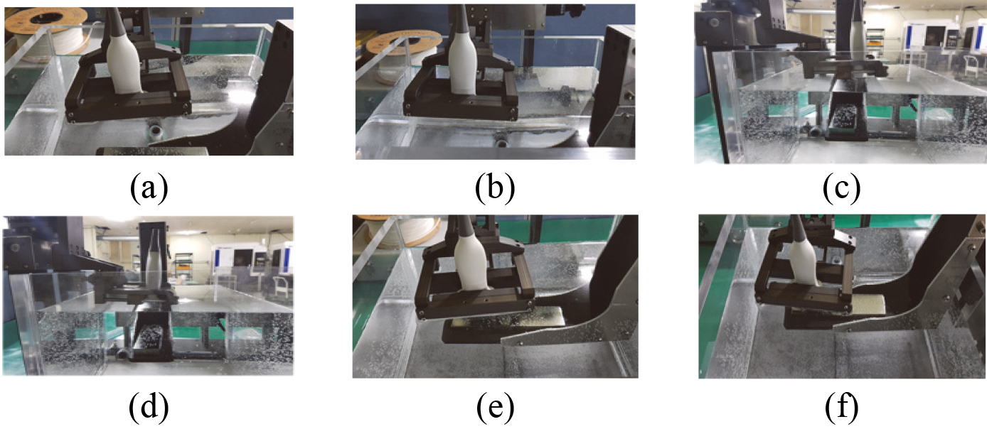
As shown in Fig. 8a and b, the probe mounted in the X-axis moves approximately 100 mm at above 50 mm from the right and left direction. As shown in Fig. 8c and d, the probe mounted in the Y-axis moves approximately 140 mm at above 50 mm from the rear and front direction. As shown in Fig. 8e and f, the probe mounted in the Z-axis moves approximately 160 mm at above 50 mm from the rear and front direction.
Figure 8.
(a) Right and (b) left movement in the X-axis; (c) rear and (d) front position movement in the Y-axis; (e) top and (f) bottom position movement in the Z-axis.
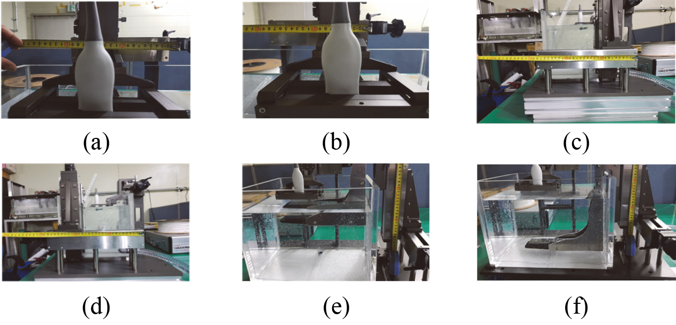
Figure 9.
Maximum angles for (a) positive and (b) negative azimuth axis; (c) maximum angles for (c) positive and (d) negative elevation axis; maximum angles for (e) positive and (f) negative tilt axis.
As shown in Fig. 9a–f, the instrument was manufactured with a structure in which the probe mounted in the azimuth, elevation, and tilt axes can move more than 5
Figure 10.
(a) Echo waveform obtained from 32-channel 2D probes and (b) their spectrum data.
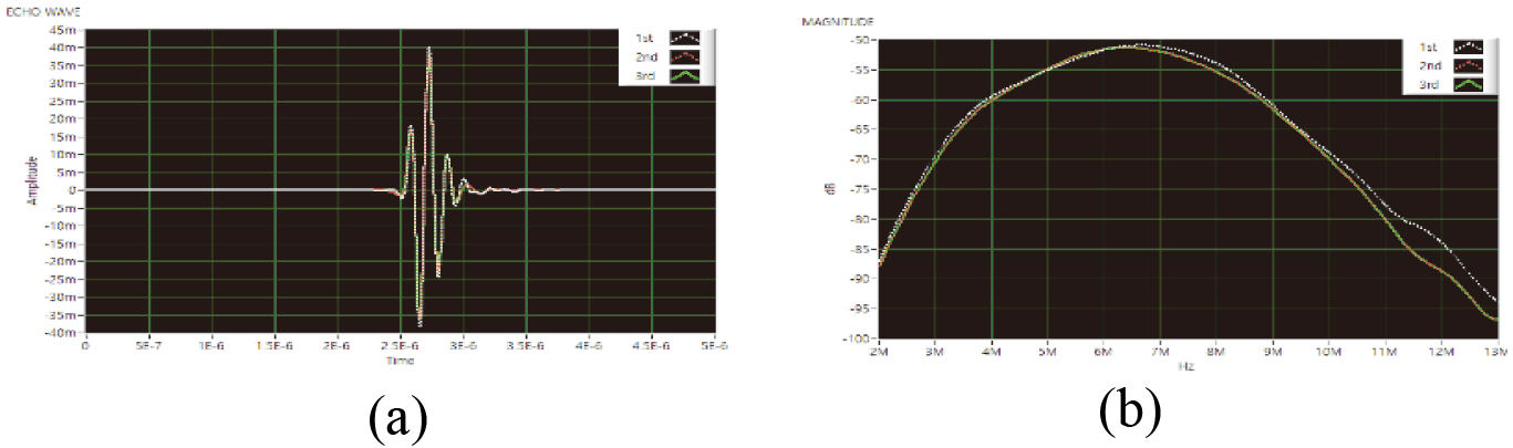
Compared with existing equipment, our alignment instrument can mount all 2D linear and convex-type probes as well as 3D-type probes. Therefore, it is expected to reduce costs by shortening inspection times and eliminating the need for additional inspection devices. The pulse-echo test is the fundamental test for ultrasonic probes, and provides various data, such as incorrect wiring between transducer elements and cables, improper doping levels of the matching and backing layers for piezoelectric materials, and mismatched electrical matching circuit design [40, 41, 42, 43]. Therefore, we performed the pulse-echo test using ultrasonic probes to evaluate the alignment instrument performance. A single-cycle pulse generated from the function generator was sent to the tested ultrasonic probes, and the echo waveform was received without any amplification. The received echo waveform was displayed in the oscilloscope; then, after fast Fourier transform, the received echo waveforms and their spectrum were obtained using LabVIEW Program. Figure 10a shows the echo waveform received at the time coordinates, which were averaged by measuring the 32-channel 10 MHz 2D probes three times. Figure 10b shows the spectrum data after fast Fourier transform. After each test, the probe was remounted and measured, and the alignment of the probe and reflected wave was repeated. After three measurements, the maximum repeat error rate of less than 5% was obtained; a similar error rate of less than 5% was also obtained for 3D probes. The measurement data indicate no mechanical interference from the instrument.
4.Conclusion
The pulse-echo test is one of the methods to evaluate the probe operation. The alignment instrument with a water tank is the basic component of the pulse-echo test. Commercial alignment instruments are very large and use complex programs along with long operation time. In addition, the fixtures for transmitting and receiving probes need to hold and support different types of ultrasonic probes. Therefore, a low-cost six-axis (X, Y, Z, azimuth, elevation, and tilt direction) alignment instrument with a water tank for mounting various 2D linear and convex and 3D probes was manufactured. The 2D probe can be pulled out using a lever on the right side of the instrument. When the lever is released, the spring is fixed again. Unlike the 2D- probe, the 3D probe has a large body shape; hence, it is possible to mount the probe in the intake part.
The probe mounted in the X-axis moves approximately 100 mm at above 50 mm from the right and left direction. The probe mounted in the Y-axis moves approximately 140 mm at above 50 mm from the rear and front direction. The probe mounted in the Z-axis moves approximately 160 mm at above 50 mm from the rear and front direction. The probe mounted in the azimuth, elevation, and tilt axes can move more than 5
Acknowledgments
This work was supported by the National Research Foundation of Korea (NRF) grant funded by the Korea government (MSIT) (No. 2020R1A2C4001606), the project for ‘Customized technology partner’ funded Korea Ministry of SMEs and Startups in 2019. (Project No. S2761601), and in part by the National Research Foundation of Korea (NRF-2018R1D1A1B07048264). The authors also thank IMP System (www.impsystem.co.kr) for fabricating the alignment instruments with the water tank.
Conflict of interest
None to report.
References
[1] | Takeda K, Erdogan H, Hansen J, Abut H. In-vehicle corpus and signal processing for driver behavior. Berlin, Germany: Springer Science & Business Media; (2009) . |
[2] | Choi H. Development of negative-group-delay circuit for high-frequency ultrasonic transducer applications. Sens Actuators, A. (2019) ; 299: : 111616. |
[3] | Daniels JM, Hoppmann RA. Practical Point-of-care Medical Ultrasound. New York, NJ, USA: Springer; (2016) . |
[4] | You K, Choi H. Wide bandwidth class-s power amplifiers for ultrasonic devices. Sensors. (2020) ; 20: (1): 290. |
[5] | Kim J, Kim K, Choe S-H, Choi H. Development of an accurate resonant frequency controlled wire ultrasound surgical instrument. Sensors. (2020) ; 20: (11): 3059. |
[6] | You K, Kim S-H, Choi H. A class-j power amplifier implementation for ultrasound device applications. Sensors. (2020) ; 20: (8): 2273. |
[7] | Shung KK. Diagnostic Ultrasound: Imaging and Blood Flow Measurements. Boca Raton, FL, USA: Taylor & Francis; (2015) . |
[8] | Sun S, Wu D, Zhu B, Zhang Y, Chen S, Yang X. Novel fabrication of a 2D ring array for real-time volumetric endoscopic ultrasound imaging. Ultrasonics. (2015) ; 60: : 6-10. |
[9] | Li J, Lan X, Lei S, Ou-Yang J, Yang X, Zhu B. Effects of carbon nanotube thermal conductivity on optoacoustic transducer performance. Carbon. (2019) ; 145: : 112-8. |
[10] | Shin S-H, Yoo W-S, Choi H. Development of public key cryptographic algorithm using matrix pattern for tele-ultrasound applications. Mathematics. (2019) ; 7: (8): 752. |
[11] | Sun P, Zhou Q, Zhu B, Wu D, Hu C, Cannata JM, et al. Design and fabrication of PIN-PMN-PT single-crystal high-frequency ultrasound transducers. IEEE Trans Ultrason Ferroelectr Freq Control. (2009) ; 56: (12): 2760-3. |
[12] | Choe S-w, Choi H. Suppression technique of hela cell proliferation using ultrasonic power amplifiers integrated with a series-diode linearizer. Sensors. (2018) ; 18: (12): 4248. |
[13] | Jeong JJ, Choi H. An impedance measurement system for piezoelectric array element transducers. Measurement. (2017) ; 97: : 138-44. |
[14] | Lam KH, Li Y, Li Y, Lim HG, Zhou Q, Shung KK. Multifunctional single beam acoustic tweezer for non-invasive cell/organism manipulation and tissue imaging. Sci Rep. (2016) ; 6: : 37554. |
[15] | Choi H, Ryu J-M, Choe S-w. A novel therapeutic instrument using an ultrasound-light-emitting diode with an adjustable telephoto lens for suppression of tumor cell proliferation. Measurement. (2019) ; 147: : 106865. |
[16] | Nakamura K. Ultrasonic Transducers: Materials and Design for Sensors, Actuators and Medical Applications. Amsterdam, The Netherlands: Elsevier; (2012) . |
[17] | Soni NJ, Arntfield R, Kory P. Point of Care Ultrasound. Oxford, United Kingdom: Elsevier Health Sciences; (2014) . |
[18] | Brunner E. How ultrasound system considerations influence front-end component choice. Analog Dialogue. (2002) ; 36: (3): 1-4. |
[19] | Choi H. Stacked transistor bias circuit of class-b amplifier for portable ultrasound systems. Sensors. (2019) ; 19: (23): 5252. |
[20] | Qiu W, Yu Y, Chabok HR, Liu C, Tsang FK, Zhou Q, et al. A flexible annular-array imaging platform for micro-ultrasound. IEEE Trans Ultrason Ferroelectr Freq Control. (2013) ; 60: (1): 178-86. |
[21] | Ou-Yang J, Zhu B, Zhang Y, Chen S, Yang X, Wei W. New KNN-based lead-free piezoelectric ceramic for high-frequency ultrasound transducer applications. Appl Phys A. (2015) ; 118: (4): 1177-81. |
[22] | Lam KH, Ji HF, Zheng F, Ren W, Zhou Q, Shung KK. Development of lead-free single-element ultrahigh frequency (170–320 MHz) ultrasonic transducers. Ultrasonics. (2013) ; 53: (5): 1033-8. |
[23] | Choi H, Choe S-w. Acoustic stimulation by shunt-diode pre-linearizer using very high frequency piezoelectric transducer for cancer therapeutics. Sensors. (2019) ; 19: (2): 357. |
[24] | Choi H. Prelinearized class-b power amplifier for piezoelectric transducers and portable ultrasound systems. Sensors. (2019) ; 19: (2): 287. |
[25] | Suri JS, Kathuria C, Chang R-F, Molinar F, Fenster A. Advances in Diagnostic and Therapeutic Ultrasound Imaging. Norwood, MA, USA: Artech House; (2008) . |
[26] | Choi H, Choe S-w. Therapeutic effect enhancement by dual-bias high-voltage circuit of transmit amplifier for immersion ultrasound transducer applications. Sensors. (2018) ; 18: (12): 4210. |
[27] | Weibao Q, Yanyan Y, Fu Keung T, Lei S. A multifunctional, reconfigurable pulse generator for high-frequency ultrasound imaging. IEEE Trans Ultrason Ferroelectr Freq Control. (2012) ; 59: (7): 1558-67. |
[28] | Choi H, Park C, Kim J, Jung H. Bias-voltage stabilizer for HVHF amplifiers in VHF pulse-echo measurement systems. Sensors. (2017) ; 17: (10): 2425. |
[29] | T.L.Szabo. Diagnostic Ultrasound Imaging: Inside Out. London, UK: Elsevier Academic Press; (2013) . |
[30] | Lumb P. Critical Care Ultrasound. Oxford, United Kingdom: Elsevier Health Sciences; (2014) . |
[31] | Hoskins PR, Martin K, Thrush A. Diagnostic Ultrasound: Physics and Equipment. Cambridge, United Kingdom: Cambridge University Press; (2019) . |
[32] | Choi H. Development of a class-c power amplifier with diode expander architecture for point-of-care ultrasound systems. Micromachines. (2019) ; 10: (10): 697. |
[33] | Choi H, Yeom J-Y, Ryu J-M. Development of a multiwavelength visible-range-supported opto-ultrasound instrument using a light-emitting diode and ultrasound transducer. Sensors. (2018) ; 18: (10): 3324. |
[34] | Shung KK, Thieme GA. Ultrasonic Scattering in Biological Tissues. Boca Raton, FL, USA: CRC press; (1992) . |
[35] | Choi H. Class-c linearized amplifier for portable ultrasound instruments. Sensors. (2019) ; 19: (4): 898. |
[36] | Choi H, Yoon C, Yeom J-Y. A wideband high-voltage power amplifier post-linearizer for medical ultrasound transducers. Appl Sci. (2017) ; 7: (4): 354. |
[37] | Chen R, Wu J, Lam KH, Yao L, Zhou Q, Tian J, et al. Thermal-independent properties of PIN-PMN-PT single-crystal linear-array ultrasonic transducers. IEEE Trans Ultrason Ferroelectr Freq Control. (2012) ; 59: (12): 2777-84. |
[38] | Choi H, Ryu J-M, Yeom J-Y. Development of a double-gauss lens based setup for optoacoustic applications. Sensors. (2017) ; 17: (3): 496. |
[39] | Choi H, Jeong JJ, Kim J. Development of an estimation instrument of acoustic lens properties for medical ultrasound transducers. J Healthcare Eng. 2017: (Sup1): 7. |
[40] | Zhu B, Chan NY, Dai J, Shung KK, Takeuchi S, Zhou Q. New fabrication of high-frequency (100-MHz) ultrasound PZT film kerfless linear array. IEEE Trans Ultrason Ferroelectr Freq Control. (2013) ; 60: (4): 854-7. |
[41] | Choi H, Choe S-w, Ryu J-M. A macro lens-based optical system design for phototherapeutic instrumentation. Sensors. (2019) ; 19: (24): 5427. |
[42] | Wang X, Seetohul V, Chen R, Zhang Z, Qian M, Shi Z, et al. Development of a mechanical scanning device with high-frequency ultrasound transducer for ultrasonic capsule endoscopy. IEEE Trans Med Imaging. (2017) ; 36: (9): 1922-9. |
[43] | Choi H, Woo PC, Yeom J-Y, Yoon C. Power MOSFET linearizer of a high-voltage power amplifier for high-frequency pulse-echo instrumentation. Sensors. (2017) ; 17: (4): 764. |


