
Development of a transcranial direct current stimulation (tDCS) device based on polarity interchangeable electrodes
Abstract
BACKGROUND:
Transcranial direct current stimulation (tDCS) is a noninvasive brain stimulation technique that can help modulate cortical excitability by transmitting direct current (DC) between a pair of scalp electrodes. To date, most studies on tDCS have been relatively short-lived, and the DC stimulations only lasted a few minutes. Conventional tDCS devices usually have some problems such as needing a lot of patches and lead lines.
OBJECTIVE:
Since conventional tDCS devices are unsuitable for use in long-term stimulations, we developed a new tDCS which can easily be used by unskilled persons.
METHODS:
We developed a new tDCS device that does not have lead lines for tDCS electrodes and has a simple structure.
RESULT:
This device can achieve stimulation with polarity interchangeable DC without physically swapping the anode and cathode. The performance of the proposed device was verified through an experiment.
CONCLUSION:
The developed tDCS device can contribute to long-term research as it uses neuroelectric stimulation.
1.Introduction
Two methods of non-invasive electromagnetic stimulation of the human brain have dominated research studies in the past few decades: transcranial magnetic stimulation (TMS), which activates axons via short-pulsed stimulation and thereby eliciting new action potentials; and transcranial electric stimulation, which is the more predominant method [1]. Although the effect of transcranial direct current stimulation (tDCS) is similar to that of repetitive TMS (rTMS), tDCS has garnered attention in the neurosciences because of its advantages over rTMS, including better mobility, increased safety, and lower cost [2, 3, 4].
Recently, transcranial stimulation paradigms have received increased interest as tools for modulating cortical excitability and behavior in diverse clinical settings and experimental conditions. tDCS is a paradigm that holds particular promise in both settings as it is noninvasive, painless, and tolerated well [1]; it is capable of modifying neuronal resting membrane potentials and the level of spontaneous neuronal firing in the area of stimulation as well as in interconnected neural networks [5]. tDCS has shown to have beneficial therapeutic effects for various diseases such as stroke, refractory epilepsy, chronic depression, drug cravings, fibromyalgia, and traumatic spinal cord injury [6, 7, 8, 9, 10, 11, 12].
The behavioral effects from these studies were relatively short-lived, and the direct current (DC) stimulations only lasted a few minutes. Several studies have shown that early evidence for spaced sessions might increase the durations of these behavioral effects to several weeks in both healthy controls and patients [9, 13, 14]. Recent advances in the field have renewed and expanded interest in long-term DC stimulations and spaced sessions; thus, further research is needed. However, most of the conventional tDCS devices are hard to use for unskilled operators because they need to attach a lot of patches and lead lines to the subjects, which requires precision and experience. Therefore, there is need to develop a tDCS device that can be easily used by everyone.
In order to overcome this operational issue, we developed a new polarity interchangeable tDCS device. This device has a simple structure to enable easy usage, and it can stimulate polarity interchanges using an interchange circuit unit. The performance of the proposed device is verified through an experiment, where the output current is measured.
2.Theory and methods
2.1 Theory of tDCS
The application of tDCS produces polarizing currents, and the effects of weak polarizing currents are critically dependent on the strength and the duration of the applied current [1]. DC stimulation is generally described in terms of the current density. Current density is defined as the electric current flow per unit cross-sectional area; then, the current density
(1)
where
(2)
Thus, when
(3)
Since the total charge and active area are inversely proportional to each other, the electrode size of the tDCS device that is commonly applied at the forehead needs a larger area. Besides, it is very important to decide on not only the active area but also the current direction because tDCS induces polarization of the brain tissue. The current direction for the tDCS is determined by the positions of the anode and cathode.
2.2Concept of the proposed tDCS device
Figure 1 shows the conceptual schematic of the proposed tDCS device. The device consists of three main parts: display, microcontrol unit (MCU), and power supply. The proposed device is operated by a 3.7-V lithum-ion battery, and the liquid crystal display (LCD) is represented by the serial peripheral interface (SPI) of the MCU. The main printed circuit board (PCB) and power PCB simulate the direct current by the input and output (I/O) signals.
Figure 1.
Schematic of the proposed tDCS device: (a) signal and power flowchart, and (b) mode of attachment of the proposed tDCS device.
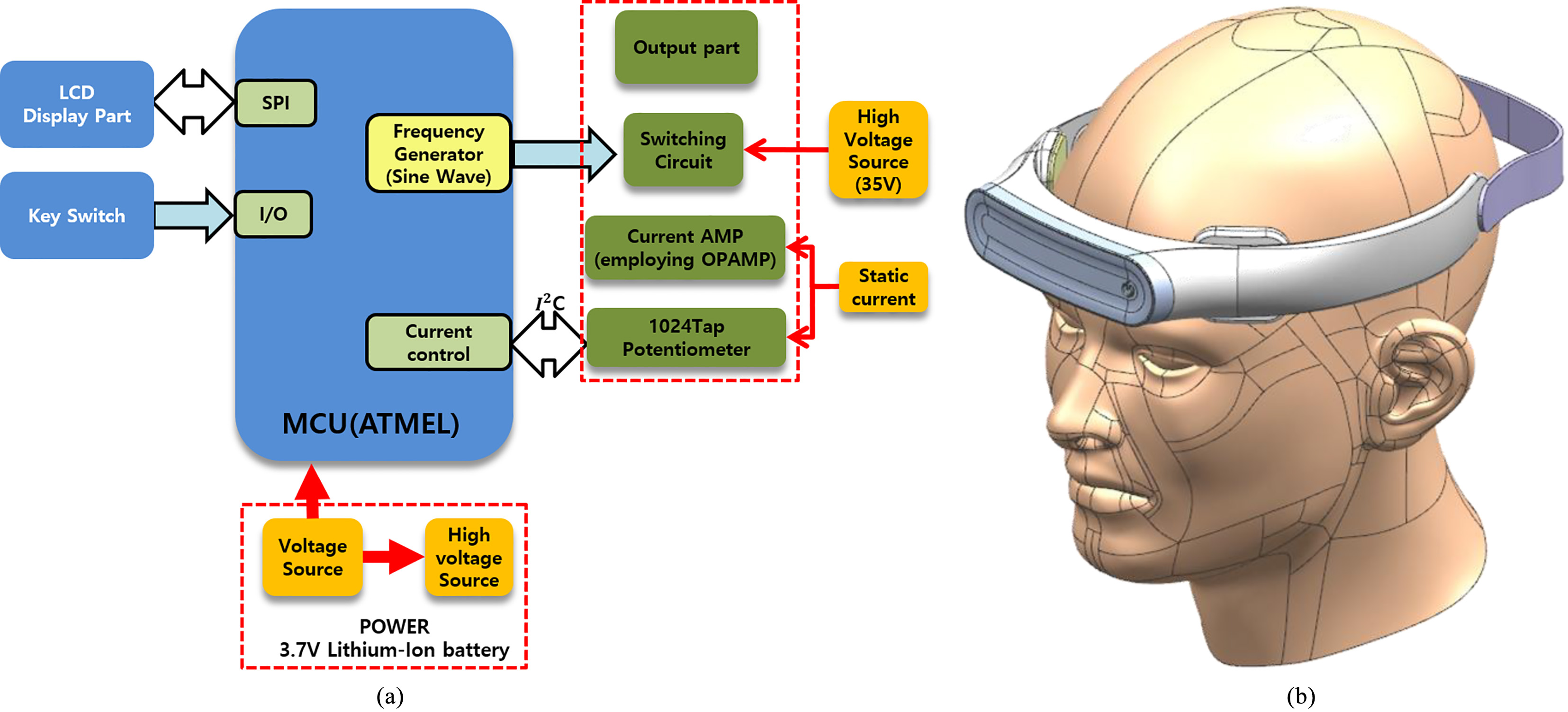
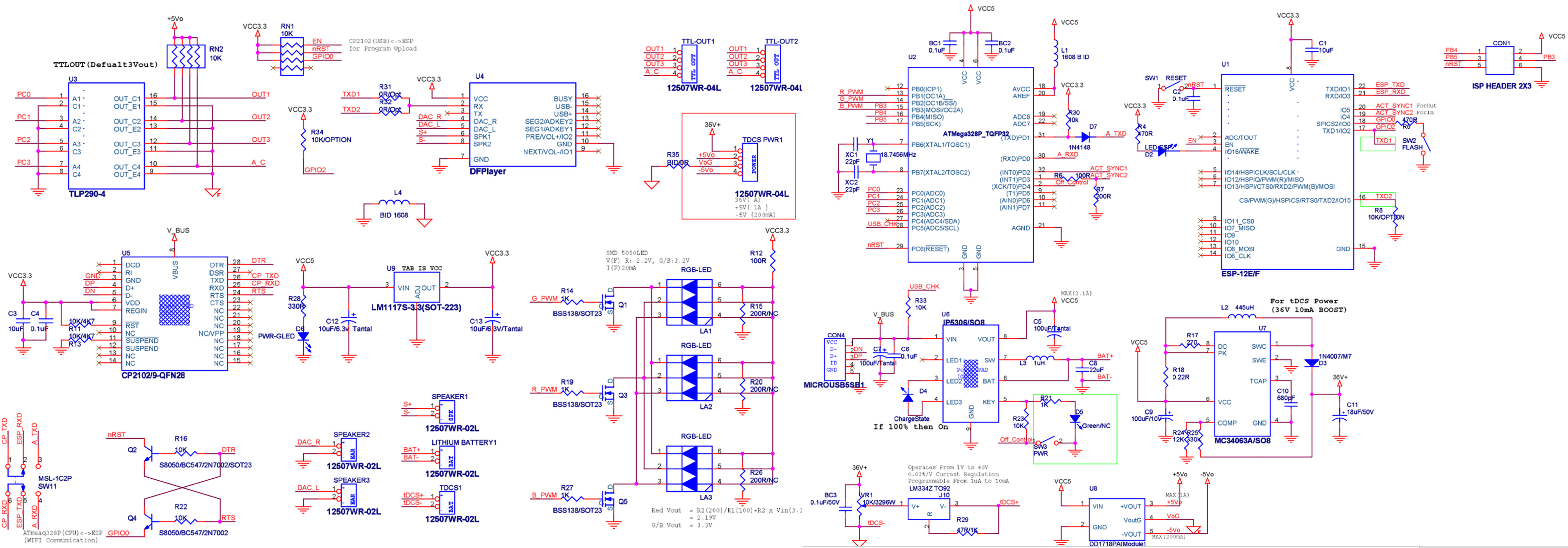
Figure 2 shows the circuit diagram of the main PCB. It consists of the MCU, power unit, battery unit, light emitting diode (LED) unit, and Wi-Fi unit. The power unit operates by receiving 3.7-V input from the battery. Then, the MCU controls the LED and Wi-Fi units, and DC is generated at the I/O pin of the MCU connected to the power PCB. Figure 3 shows the circuit diagram, layout, and assembled PCB of the power unit. The power unit consists of a constant current chip, connector, switch chip, and so on. The constant current chip operates by receiving a constant voltage through the switch and produces output currents at three steps, namely 0.6 mA, 1.2 mA, and 1.8 mA. The switch controls the on and off for receiving the signal of 3.3–5 V through the connector. The layout has a 6 mm wire gauge, two printed layers, 1.6 T, and a finished PCB size of 34.92
2.3Implementation of the polarity interchangeable tDCS
Figure 4 shows the circuit diagram, layout, and assembled PCB of polarity interchangeable PCB. The polarity interchange circuit works on 3.3–5 V, and the output signal can interchange the separating anode and cathode to operate the switch according to the signal. The layout has a 6 mm wire gauge, two layers, 1.6 T, and a finished size of 34.92
2.4Manufacturing of the proposed tDCS device
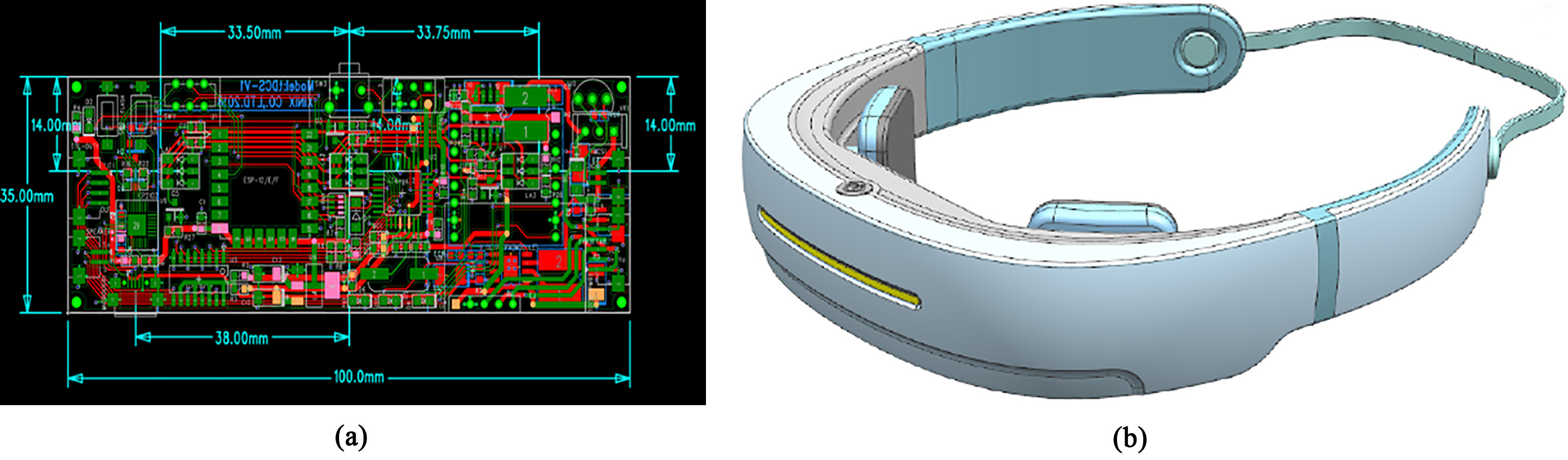
A combined layout is designed from the circuits. Figure 5a shows the layout of the combined main control equipment. The layout has 6 mm of wire gauge, 2 layers, 1.6 T, and is of the size of 100 mm
Figure 2.
Schematic of the main PCB.
the battery, connector, and battery charging IC chip are located at the back. Figure 5b shows the design of the proposed tDCS device. The final design had a fixed band and was easy to attach to a stimulation pad. The proposed device has an LED display at the center in the front, the power button is at the center on the top of the device, and the DC stimulation pad is at the face and it touches the forehead.
Figure 3.
Schematic of the power unit.
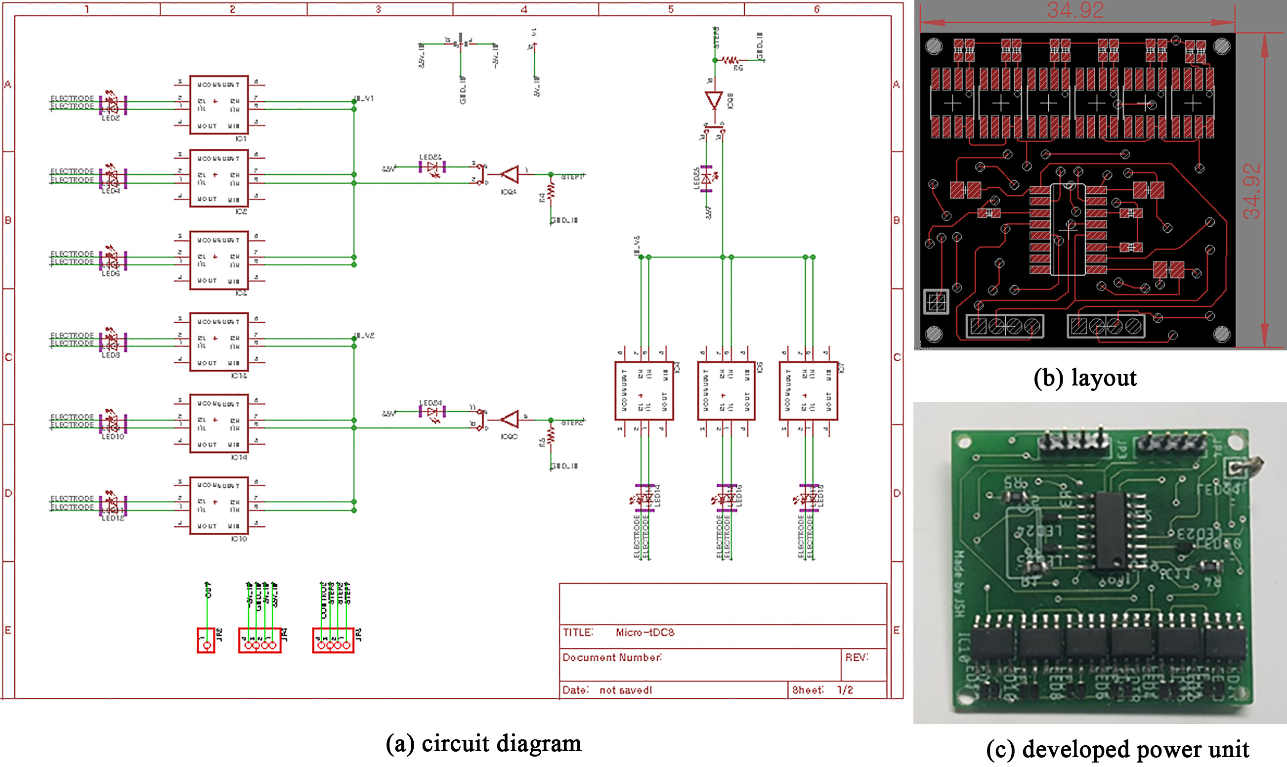
Figure 4.
Schematic of the polarity interchange PCB.
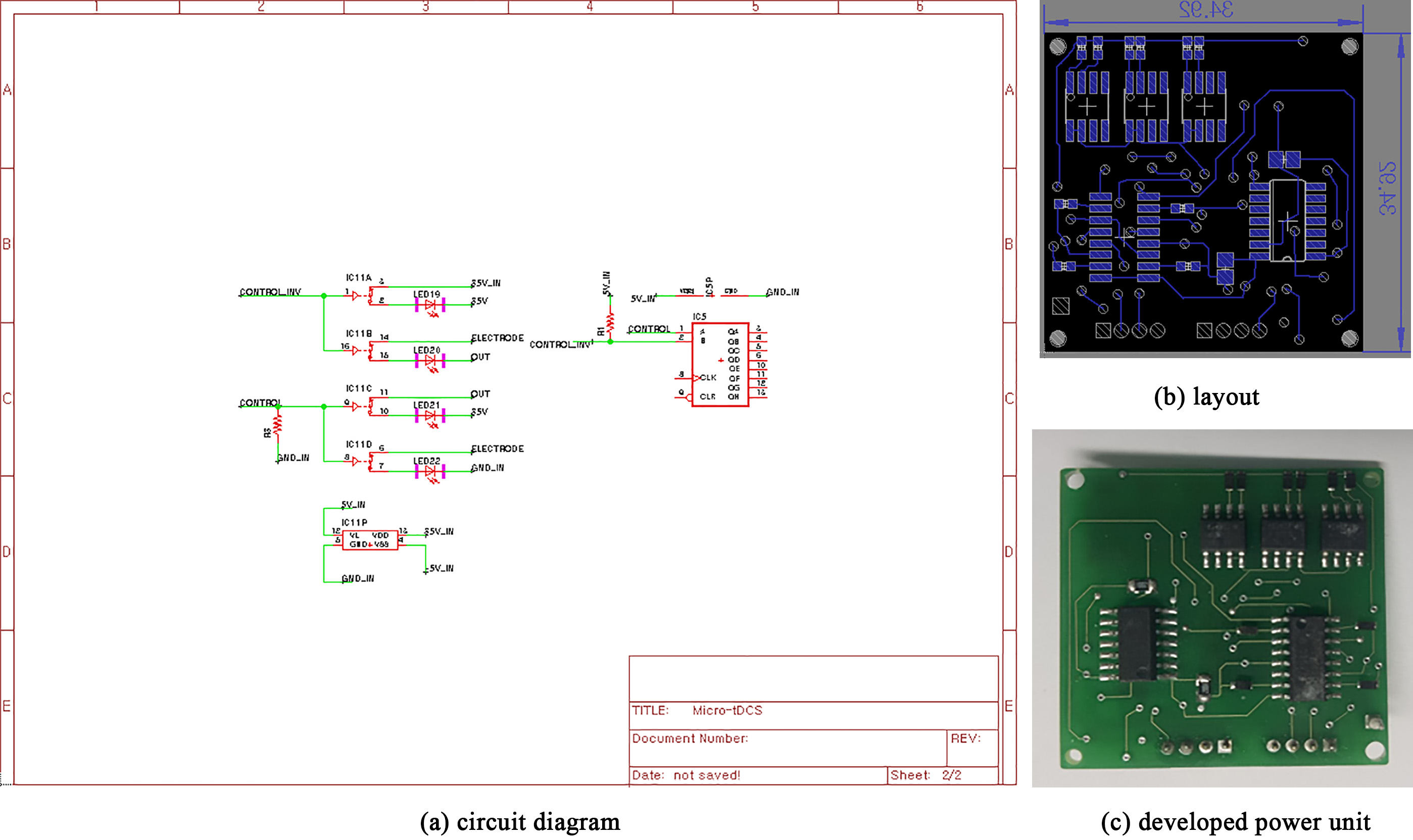
Table 1
Accuracy of the output current
| Ideal value | Average value | Mean of error | STD of error | |
|---|---|---|---|---|
| Current step1 | 600 | 599.9 | 0.0120% | 0.0076 |
| Current step2 | 1200 | 1201.0 | 0.0863% | 0.0041 |
| Current step3 | 1800 | 1801.2 | 0.0667% | 0.0036 |
Figure 5.
Proposed tDCS device: (a) layout of the main control PCB, and (b) design of the device.
3.Results
3.1tDCS hardware system
Figure 6.
Developed tDCS device: (a) main controller, and (b) assembled device.
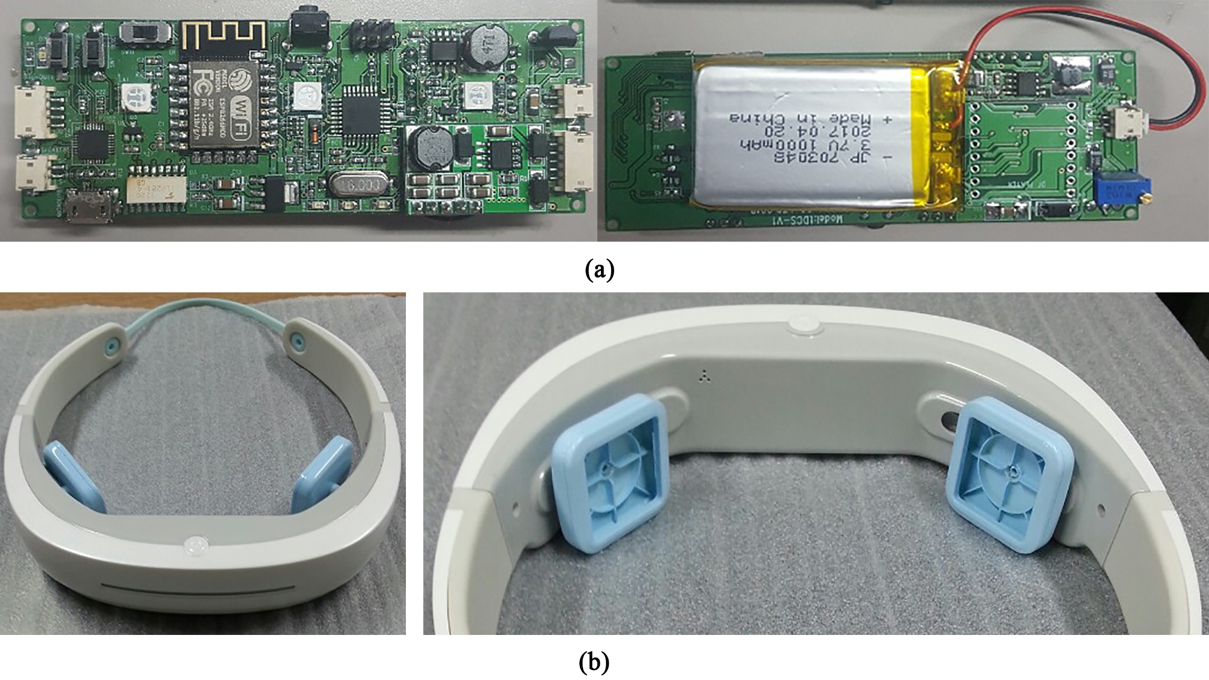
Figure 7.
Result of the current interchange.
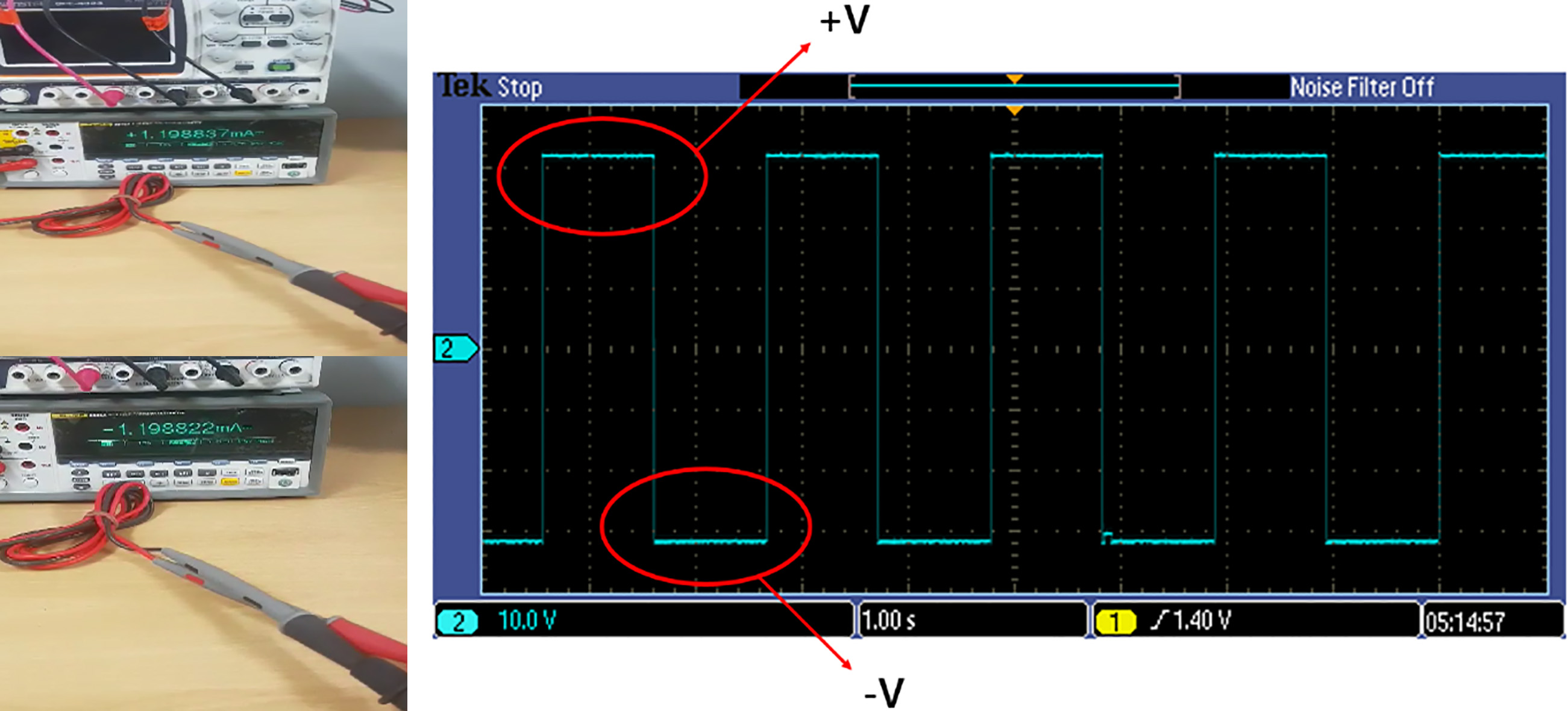
Figure 8.
tDCS simulation result from COMETs software. The first column shows the electrode location and shape (3 cm
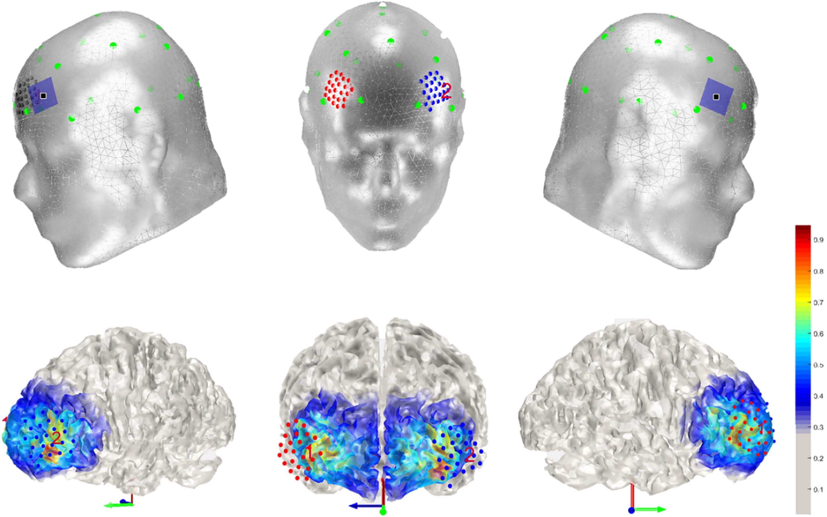
Figure 6 shows the assembled main control PCB. Figure 6a shows the developed main controller using the designed PCBs of size 100 mm
3.2Evaluation of tDCS current stimulation
In order to evaluate the performance of the developed tDCS, the output current was measured over 25 times in the experiment with the various conditions. The accuracy of the output current is presented in Table 1. The result shows very high accuracy and the total current error is extremely low (0.0589%). Figure 7 shows the features of the proposed tDCS system, where interchangeable electrodes with one physical electrode can also be used. When the ideal current is
3.3tDCS simulation for forehead stimulation using COMETs software
In order to understand the simulated area on the brain cortex, COMETs software was employed to show 3D stimulated images. The tDCS electrode has a rectangular shape of the size 3.0 cm
4.Conclusion
In this study, we developed a new tDCS device that can be worn with polarity interchangeable electrodes. The developed device had a minimized main controller, 3.7 V battery, and horizontal movable case of a stimulation pad. The performance of the proposed device showed extremely high accuracy (the STD of error was under 0.01%). A very low STD of error implies that the proposed device has the potential for simultaneous use of EEG and the tDCS system because the proposed system can enhance the SNR of the EEG signal during the tDCS stimulation on the brain.
Since the developed device does not need any lead lines for the electrode and is easy to wear, we expect that it can be easily used by not only experts but also unskilled persons. Moreover, it can stimulate the polarity interchangeable DC without moving the position of the anode and cathode. As a result, the developed tDCS device can contribute to the research by using tDCS stimulation in spaced sessions and long-term stimulation.
Acknowledgments
This research was supported in part by the Brain Research Program through the National Research Foundation of Korea (NRF) funded by the Ministry of Science, ICT and Future Planning (no. NRF-2015M3C7A1031969), the National Research Foundation of Korea (NRF) grants funded by the Korean Government (MSIP) (no. NRF-2017R1A2A1A05000730), the strengthening competitiveness of industrial clusters through the Korea Industrial Complex Corporation (no. RKN18004), and the BB21
Conflict of interest
None to report.
References
[1] | Stagg CJ, Nitsche MA. Physiological basis of transcranial direct current stimulation. The Neuroscientist. (2011) ; 17: (1): 37-53. |
[2] | Williams JA, Imamura M, Fregni F. Updates on the use of non-invasive brain stimulation in physical and rehabilitation medicine. Journal of Rehabilitation Medicine. (2009) ; 41: (5): 305-11. |
[3] | Nitsche MA, Cohen LG, Wassermann EM, Priori A, Lang N, Antal A, et al. Transcranial direct current stimulation: State of the art 2008. Brain Stimulation. (2008) ; 1: (3): 206-23. |
[4] | Jung Y-J, Kim J-H, Im C-H. COMETS: A MATLAB toolbox for simulating local electric fields generated by transcranial direct current stimulation (tDCS). Biomedical Engineering Letters. (2013) ; 3: (1): 39-46. |
[5] | Villamar MF, Santos Portilla A, Fregni F, Zafonte R. Noninvasive brain stimulation to modulate neuroplasticity in traumatic brain injury. Neuromodulation: Technology at the Neural Interface. (2012) ; 15: (4): 326-38. |
[6] | Fregni F, Boggio PS, Mansur CG, Wagner T, Ferreira MJ, Lima MC, et al. Transcranial direct current stimulation of the unaffected hemisphere in stroke patients. Neuroreport. (2005) ; 16: (14): 1551-5. |
[7] | Hummel F, Celnik P, Giraux P, Floel A, Wu W-H, Gerloff C, et al. Effects of non-invasive cortical stimulation on skilled motor function in chronic stroke. Brain. (2005) ; 128: (3): 490-9. |
[8] | Fregni F, Thome-Souza S, Nitsche MA, Freedman SD, Valente KD, Pascual-Leone A. A controlled clinical trial of cathodal DC polarization in patients with refractory epilepsy. Epilepsia. (2006) ; 47: (2): 335-42. |
[9] | Boggio PS, Rigonatti SP, Ribeiro RB, Myczkowski ML, Nitsche MA, Pascual-Leone A, et al. A randomized, double-blind clinical trial on the efficacy of cortical direct current stimulation for the treatment of major depression. International Journal of Neuropsychopharmacology. (2008) ; 11: (2): 249-54. |
[10] | Fregni F, Liguori P, Fecteau S, Nitsche MA, Pascual-Leone A, Boggio PS. Cortical stimulation of the prefrontal cortex with transcranial direct current stimulation reduces cue-provoked smoking craving: A randomized, sham-controlled study. Journal of Clinical Psychiatry. (2008) ; 69: (1): 32-40. |
[11] | Fregni F, Boggio PS, Lima MC, Ferreira MJ, Wagner T, Rigonatti SP, et al. A sham-controlled, phase II trial of transcranial direct current stimulation for the treatment of central pain in traumatic spinal cord injury. Pain. (2006) ; 122: (1-2): 197-209. |
[12] | Fregni F, Gimenes R, Valle AC, Ferreira MJ, Rocha RR, Natalle L, et al. A randomized, sham-controlled, proof of principle study of transcranial direct current stimulation for the treatment of pain in fibromyalgia. Arthritis & Rheumatism: Official Journal of the American College of Rheumatology. (2006) ; 54: (12): 3988-98. |
[13] | Reis J, Schambra HM, Cohen LG, Buch ER, Fritsch B, Zarahn E, et al. Noninvasive cortical stimulation enhances motor skill acquisition over multiple days through an effect on consolidation. Proceedings of the National Academy of Sciences. (2009) ; 106: (5): 1590-5. |
[14] | Boggio PS, Nunes A, Rigonatti SP, Nitsche MA, Pascual-Leone A, Fregni F. Repeated sessions of noninvasive brain DC stimulation is associated with motor function improvement in stroke patients. Restorative Neurology and Neuroscience. (2007) ; 25: (2): 123-9. |
[15] | Heald MA, Marion JB. Classical electromagnetic radiation: Courier Corporation; (2012) . |


