
The manufacturing procedure of 3D printed models for endoscopic endonasal transsphenoidal pituitary surgery
Abstract
BACKGROUND:
Endoscopic endonasal transsphenoidal pituitary surgery is usually difficult and risky. With limited sources of cadaveric skulls, traditional methods of using virtual images to study the surgery are difficult for neurosurgeons and students because the surgery requires spatial imagination and good understanding of the patient’s conditions as well as practical experience. The three-dimensional (3D) printing technique has played an important role in clinical medicine due to its advantages of low cost, high-efficiency and customization.
OBJECTIVE:
CT images are used as the source data of 3D printing. The data obtained directly from the CT machine has limited accuracy, which cannot be printed without processing. Some commercial platforms can help build an accurate model but the cost and customization are not satisfactory. In this situation, a tactile, precise and low-cost 3D model is highly desirable.
METHODS:
Three pieces of computer software are used in the manufacturing of medical 3D models and the processing procedure is easy to understand and operate.
RESULTS:
This study proposes a practical and cost-effective method to obtain the corrected digital model and produce the 3D printed skull with complete structures of the nasal cavity, sellar region and different levels of pituitary tumors. The model is used for the endoscopic endonasal transsphenoidal pituitary surgery preparation.
CONCLUSION:
The 3D printed medical model can directly help neurosurgeons and medical students to practice their surgery skills on both general and special cases with customized structures and different levels of tumors.
1.Introduction
Skull base tumors are tumors of the skull base and neighboring structures, of which pituitary tumors are the most common, with a population prevalence rate of about 17% [1]. The complications contain acromegaly, Cushing’s syndrome and hyperpituitarism, which will cause severe loss of life and social ability.
Endoscopic endonasal transsphenoidal pituitary surgery aims to remove pituitary tumors through the nose and sphenoid sinus and is assisted by the endoscope and other operative tools [2]. The tools are used to go through the nasal cavity to the sellar region, and then break the bone to reveal the sphenoid sinus. Dealing with pituitary tumors in the sellar region is challenging, due to the intricate structure of the nose, as well as the location of the sphenoid sinus [3]. The sphenoid sinus is a cavity located roughly in the middle of the skull, behind the nose and eyes [4]. In 1992, the endoscope in the pituitary surgery was first introduced by Jankowski et al., using the endonasal transsphenoidal endoscopic technique in removal of three pituitary adenomas [5]. In 1996 and 1998, Jho and Carrau [6] and Cappabianca et al. [7] standardized transsphenoidal endoscopic guided pituitary surgery in actual clinical practice. The endoscope technique has become a significant method in pituitary surgery, which is favored by most neurosurgeons for the most kinds of pituitary tumors surgery [8].
Minimally invasive surgeries require neurosurgeons to have a good spatial imagination of body structures and understanding of patients’ conditions [9]. Specifically, to complete the endoscopic endonasal transsphenoidal pituitary surgery successfully, neurosurgeons should be familiar with the structure of the sellar region, which needs the combination of theoretical knowledge and practical experience. However, the opportuniy of practicing endoscopic endonasal transsphenoidal pituitary surgery is rare [10]. In this situation, it is beneficial for neurosurgeons to do the medical training and surgical planning on a medical model. Basically, the types of the medical model are images and cadaveric skulls. Neither virtual 3D images nor 2D atlases are sufficient for the practice and training of specific operation in the real surgery. A cadaveric skull is a good tool for the practice. However, cadaveric skulls are not efficient for the conservation and usage due to the material, the cost, and ethical concerns. Hence, the 3D printed model can be a good alternative.
The 3D printing technique, or additive manufacturing, was invented by Charles W. Hull in 1986 and has been extensively used around the world [11]. The 3D printing technology aims to convert a 3D model into slices and builds up the tactile models by depositing the material in the plane layer by layer [12]. It has recently come to the attention of the medical field, ranging from pharmaceutics and drug delivery devices to basic anatomy [13, 14], surgical simulation and further studies, due to its precise reconstruction, decreasing costs and increasing availability [15]. Yu et al. demonstrate that 3D printing technique can be helpful for the development of novel pharmaceutical products, as well as drug delivery devices [13, 14]. The applications of 3D printing are rapidly developing in different areas of clinical medicine, such as medical education and model-assisted surgeries [16, 17]. Processing the digital medical images and producing the precise and useful models has drawn the attention of both engineers and neurosurgeons. Nowadays, some companies produce the commercial medical image processing platform (like Sectra’s 3D Core and Synapse 3D) to help create the correct digital model. However, the expense and the customization could be the problems.
Over the last decade, the medical image processing and the 3D reconstruction for medical models have been developed and applied in biomedical applications. Basically, CT scanning is a popular way to get original 3D data. Sun et al. summarize the study of Computer-Aided Tissue Engineering (CATE), which contains biomimetic design and bio-manufacturing for tissue and organ regeneration [18]. They also propose the CAD-based bio-tissue informatics model, which consists of two steps: (i) image acquisition, processing and 3D reconstruction, and (ii) reverse engineering-based CAD model generation [19, 20]. The CAD-based model can provide tissue biological and biophysical information [21]. Harryson and Rose [22] propose multi-material 3D models for temporal bone surgical simulation. The image processing is done in a slice by slice style by the software Materialise Interactive Medical Image Control System (Mimics). Viana and Bartolo [23] prove that 3D data acquisition, modelling, and printing techniques can be used to obtain biometric information from cattle. The processing is done by the software MeshLab and the printed model shows minor difference [24].
In this paper, an easily-understood medical image processing method and a 3D printed model for endoscopic endonasal transsphenoidal pituitary surgery research or simulation are proposed. The novelties of our study are as follows: first, the processing operation consists of three pieces of software that tackle the inaccuracy problem of the model directly obtained from the CT scanner due to the limited accuracy of the machine; second, compared to other specialized medical image processing methods and platforms for reconstruction, this study provides a low-cost, customized and maneuverable solution for making skull models and soft tissues, which can be done by surgeons themselves; third, the model can be used directly for simulation of the surgery.
The primary goal of this study is two-fold: (i) propose a general, efficient and low-cost procedure to fix the problems of original 3D digital model due to the accuracy limitation of CT technology; (ii) make an equal size model with hard structures (skull, nasal cavity and sinuses) and soft tissues (pituitary, tumors, internal carotid arteries and optic nerves), which can be reliably used for teaching, training and preoperative planning purposes.
To obtain the initial digital model, the human head is scanned horizontally by Siemens SOMATOM Force CT scanner in the axial plane, with a slice width of 1 mm, a helical pitch of 0.9, and an image production interval of 1 mm, which is not fine enough for 3D printing.
A detailed procedure of processing the digital model is presented in Section 2. In Section 3 we describe the manufacturing process of the model, including 3D printing, making models for pituitary, tumors, internal carotid arteries and optic nerves through the molds, and how to build up the whole skull model. In Section 4 we show the results and illustrate the significance of this study. In Section 5 we discuss the results and conclude the paper. The study presents a maneuverable and low-cost approach for making a precise model with different sizes of pituitary tumors for the endoscopic endonasal transsphenoidal pituitary surgery preparation.
2.Digital model processing
2.1Overview
The accuracy of the skull’s structure is essential for a medical model. Nevertheless, the result of CT scanning technology is not accurate enough and format transformation may lead to some missing of the structure [13]. These inaccuracies and missing might result in failure during the printing [12, 24, 25]. Hence, we use 3D manipulation tools to process the original data to make sure that the printing can be done successfully. In this section, we present the method of processing the digital model and drawing the molds used for making soft tissue models. The main goals of this section are shown in Fig. 1. The figure shows the main processing operations with specific purposes and corresponding tools to make correct the 3D printed model for endoscopic endonasal transsphenoidal pituitary surgery.
Figure 1.
Overview of the main goals and operations in digital model processing.
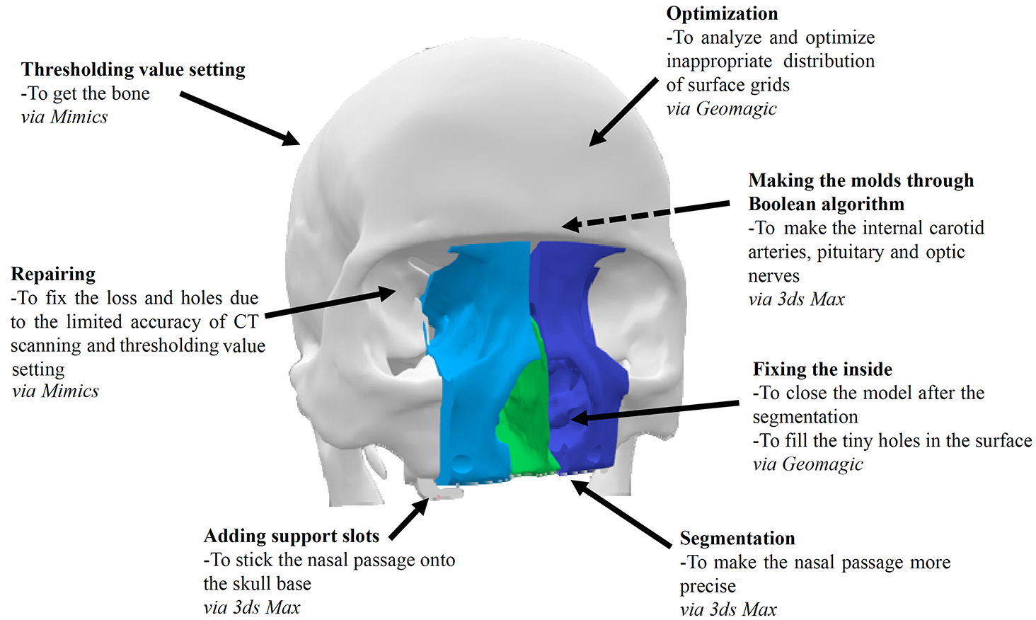
The white part of the digital model is the skull base, which is segmented from the CT data for the entire head using the ‘Thresholding’ tools of Mimics. Mimics also helps repair the holes on the base, caused by the limited accuracy of the CT scanning and the thresholding. The green part represents the septum and the blue ones represent the right and left parts of the turbinate, which are segmented by 3ds Max. These three parts make up the whole surgical area. Besides, there are two support slots at the bottom of the model, which is made by 3ds Max, to stick the nasal passage. The Geomagic software helps optimize and fix both the skull base and the surgical area. In addition, the dotted arrow refers to the soft tissues behind the nasal passage, like carotid arteries, pituitary and optic nerves, which are created by 3ds Max.
2.2Specific methods and operations
2.2.1Initial digital model segmentation
The goal of segmentation is to extract the parts we need from the medical data. Specifically, we are interested in the bone of the skull, especially the surgical area, including the nasal cavity and the sellar region.
Figure 2.
Set the thresholding value for Bone (CT). We select Menu bar
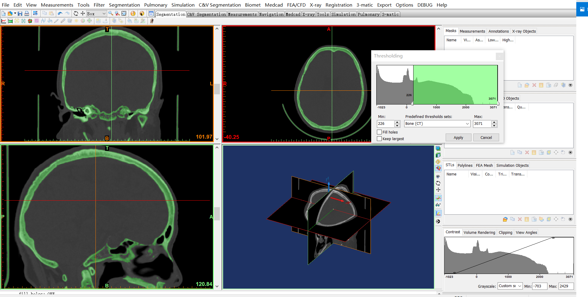
The automatic threshold segmentation tool is an effective and common tool to easily distinguish the bone from CT images based on the thresholding value [26], which can be completed in Mimics (see Fig. 2). Mimics is developed by Materialise, a Belgian company specialized in 3D printing technology. Mimics is a 3D medical image processing software with advanced segmentation and mask editing tools. Besides, the scanned data is exported to a DICOM file, which can be loaded by Mimics. The limited accuracy of CT scanning and threshold segmentation may cause missing features and unexpected holes in the digital model. To complete the file format transformation and segmentation at the very beginning, we choose Mimics, which can convert DICOM file into STereoLithography (STL) file.
Specifically, the ‘Thresholding’ tool is used to create a first definition of the segmentation object. The segmentation object will contain all pixels in the images with a value higher than or equal to the thresholding value [27].
Figure 3.
Keep the surgical area (the nasal cavity and the sellar region) section and remove other parts. (a) Select Menu bar
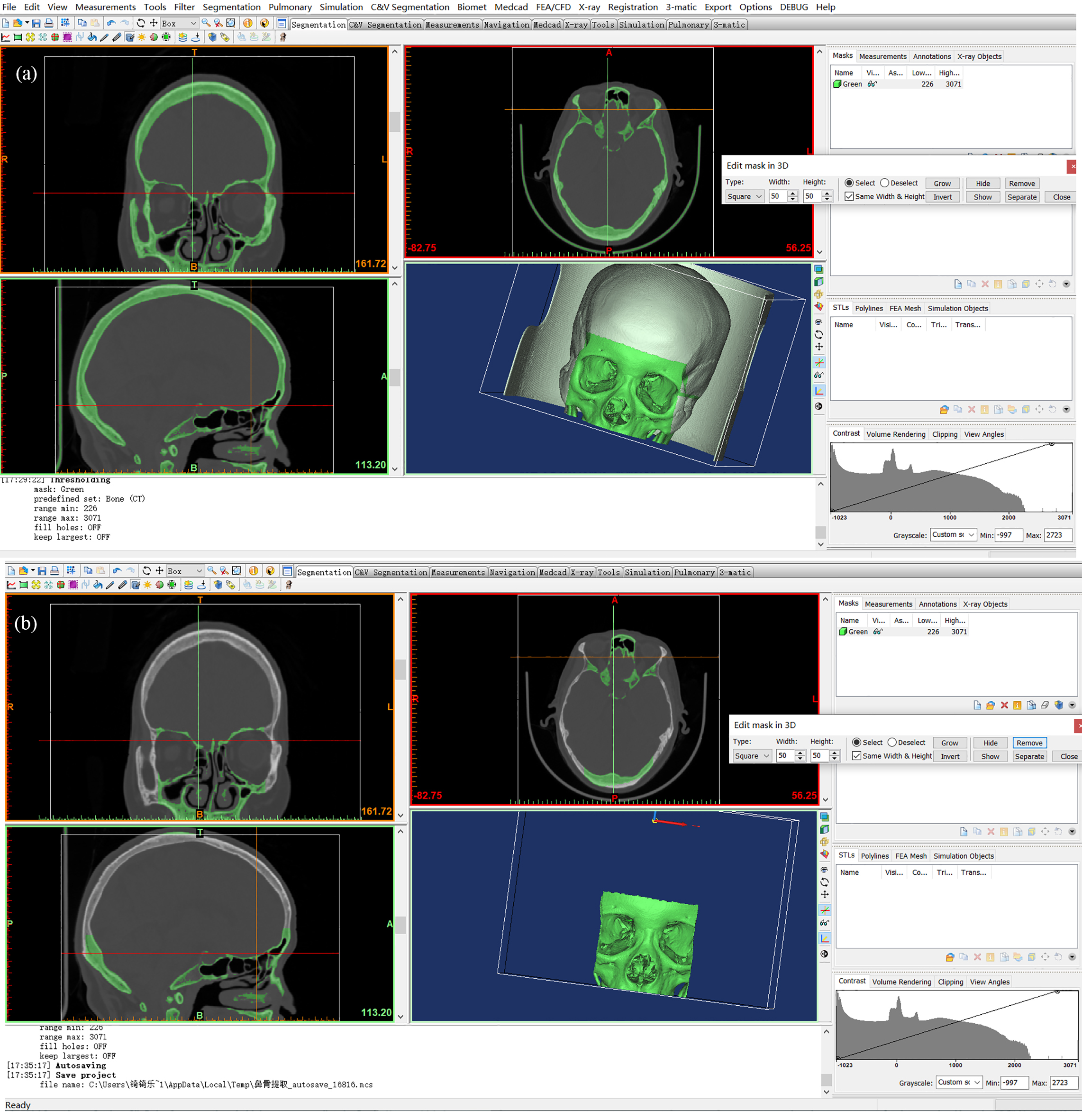
After segmentation, the model is exported directly as the base. We extract the part for the surgical area separately, as we focus on this part in this study (see Fig. 3).
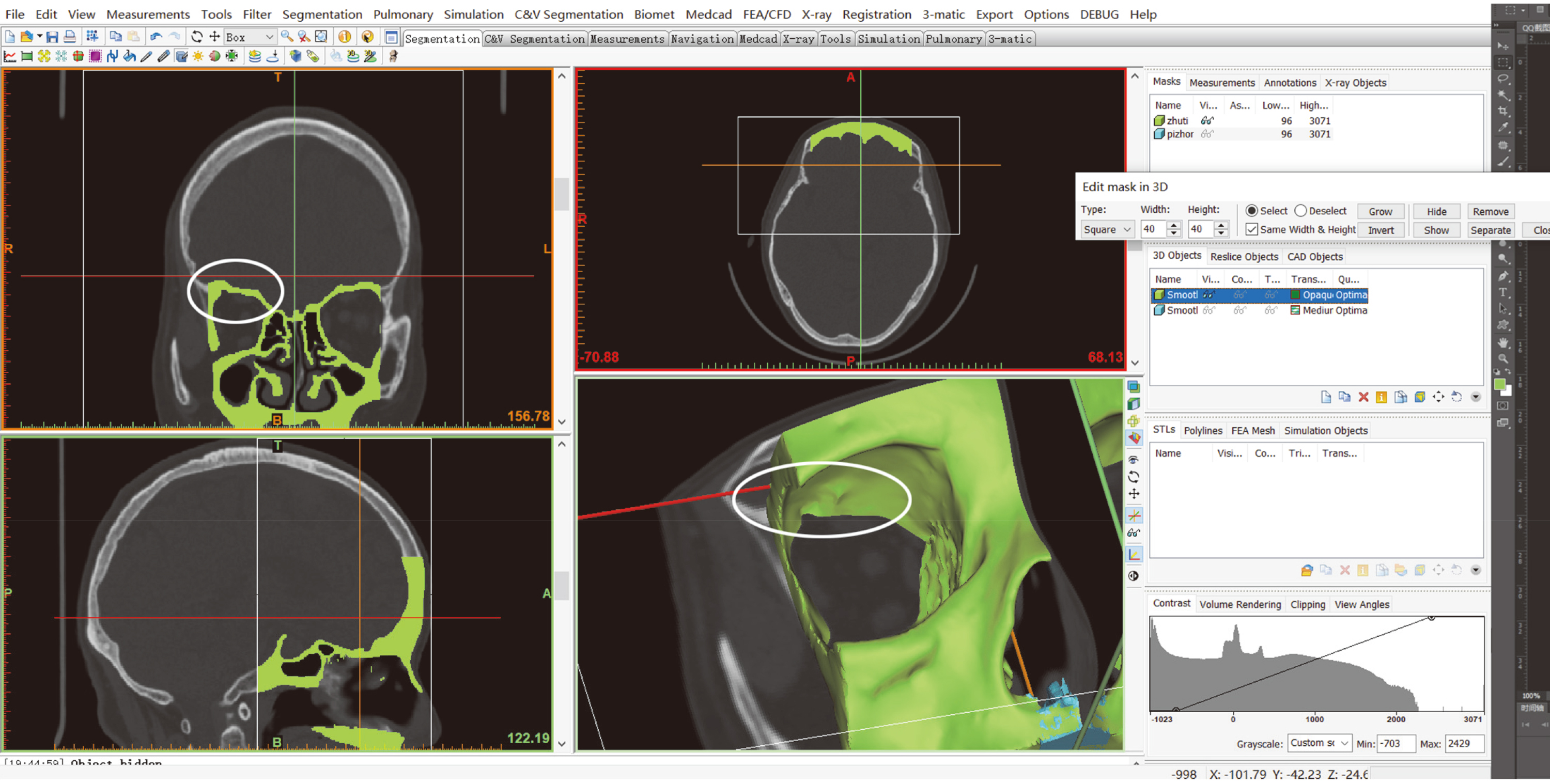
In the ‘Edit Mask in 3D’ tool, we can visualize and edit the mask in 3D. On this 3D preview we can specify a region. The pixels that correspond to this selection can be removed from the mask or separated into a new mask [27].
2.2.2Digital model repairing
Once we extract the part needed, we must repair it to meet the requirement for the surgery simulation. Some unexpected holes are obvious, like the ones in Fig. 4 on both the section slice and the 3D object.
Figure 4.
An unexpected hole on the model.
The 3D object is the result of many slices overlaying, in which case we complete the hole repairing slice by slice. We show the operation in Fig. 5 and the corresponding result in Fig. 6.
Figure 5.
Fix the hole by drawing slice by slice. We use Menu bar
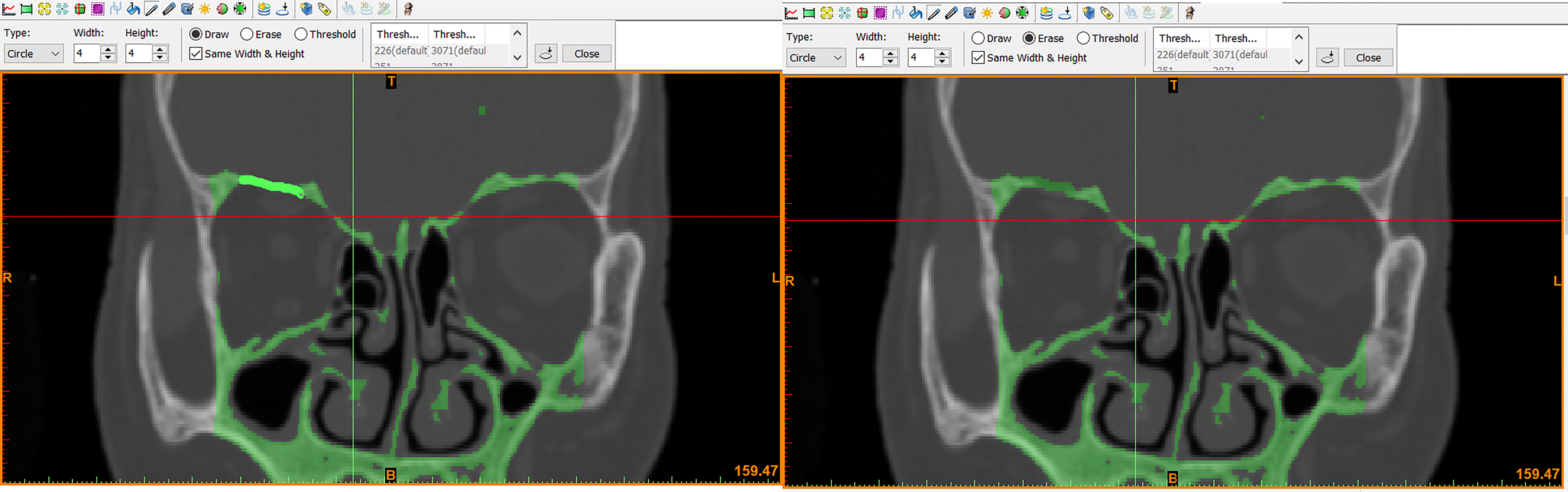
Figure 6.
The hole is fixed.
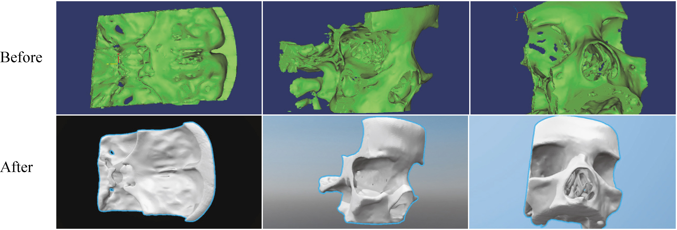
Similarly, we fix other holes, especially on the pituitary nest, the orbital bone of the eye and the middle turbinate position and obtain an integral model of nasal cavity (see Fig. 7).
Figure 7.
Comparison of the surgical area model before and after the repair.
After the repair, the nasal septum section is exported and removed from this model for further segmentation. Subsequently, the complete corrected surgical area model can be saved as an STL file.
2.2.3Further segmentation
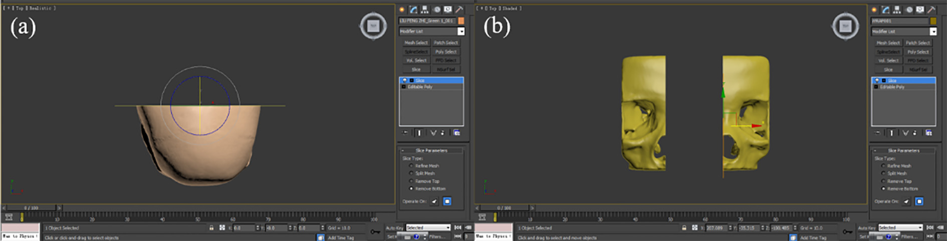
To check the inner structure and save the cost, only the front half part of the skull is kept. Also, the real turbinate is soft, which requires more processes to simulate the surgery better. Hence, we further split the model.
‘Cut’ is a direct way to achieve our goals and there is a very convenient ‘Cutter’ tool in 3ds Max to do so. This tool provides many options to slice and dice one set of objects with another [28]. Here we use the tool to process the surgical area, with details below.
For this study, we use 3ds Max mainly for the segmentation and the mold manufacturing.
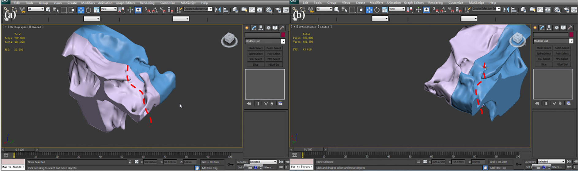
The corrected surgical area model and the skull base can be converted to an editable polygon. Since the surgical area is kept, the ‘Slice’ function is used to remove the back of the skull (Fig. 8a). For the nasal cavity model, as the turbinate and the septum need processing later, the model is cut in half, through the ‘Slice’ operation (Fig. 8b).
Figure 8.
Slicing operations on the skull base and the nasal cavity.
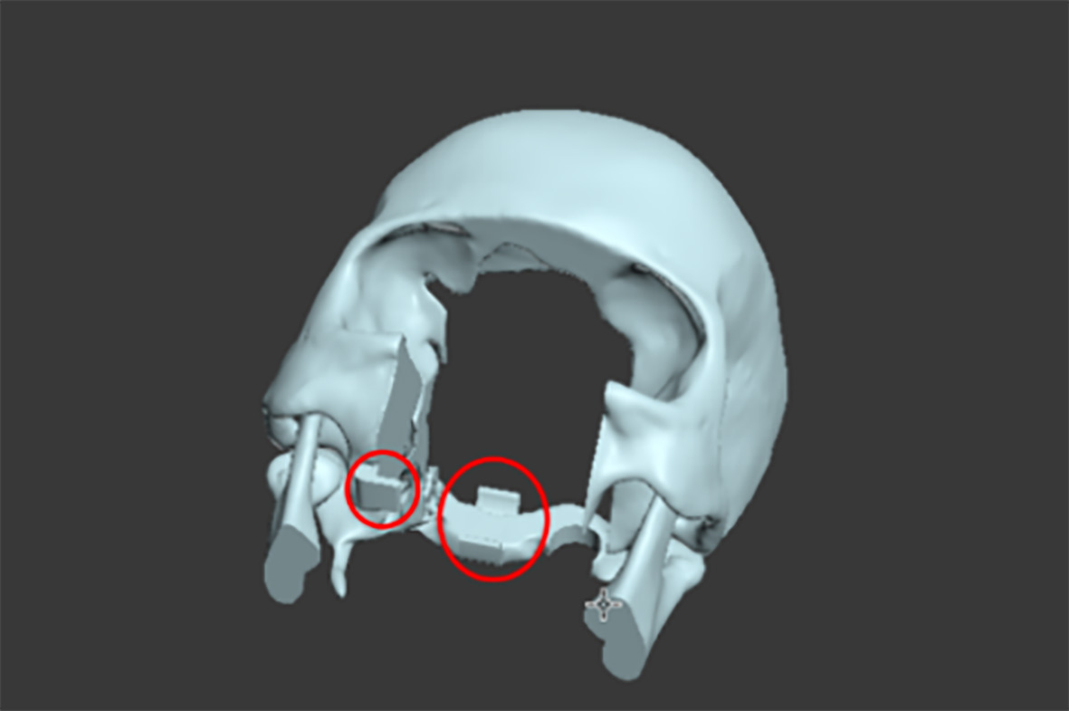
To stick the nasal cavity and sellar region parts on the skull base, some supports are added on the skull base (Fig. 9).
Figure 9.
The skull base with supports.
2.2.4Soft tissues and corresponding molds design
During the real operation, internal carotid arteries are exposed, which should not be touched in the surgery. Hence, there must be visible parts of the arteries to help simulate the surgery better.
Basically, there are trajectories for the internal carotid arteries on the back of the skull model (in Fig. 10) which can be followed when drawing the arteries.
Figure 10.
The trajectories for the internal carotid arteries.
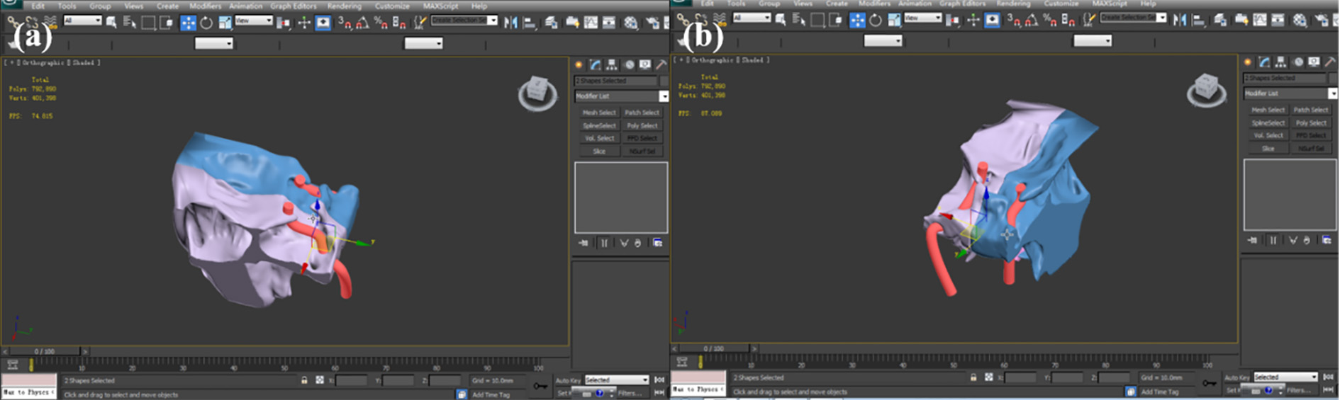
Then the ‘Line’ of the drawing toolbox is applied. The line is drawn with several inflection points which are selected and moved to make the line fit the trajectory and the skull. Subsequently, right-click the line to select the ‘Smooth’ to make it a curve and use ‘Rendering’ to set the parameters for the diameter and color of the line, making it like a real artery (Fig. 11). Similarly, optic nerves can be made.
Figure 11.
The complete internal carotid arteries. (a) Top left perspective. (b) Top right perspective.
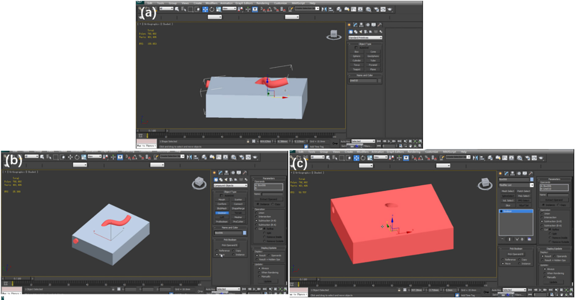
Since printing soft tissues directly is complicated and highly costly, we choose molding as an alternative [29, 30]. The material is poured into the mold and is taken out after the solidification. We take the internal carotid arteries for an example.
First, make a box, which can contain the artery part we want. Second, put the box and the artery together and make them overlapping (in Fig. 12a). Then select Compound Objects
Figure 12.
(a) Make the box and artery overlaying. (b) Run the Boolean algorithm. (c) Get the mold.
Similarly, make molds for the face and the pituitary with optic nerves (Fig. 13).
Figure 13.
Molds for (a) the face and (b) the pituitary with optic nerves.
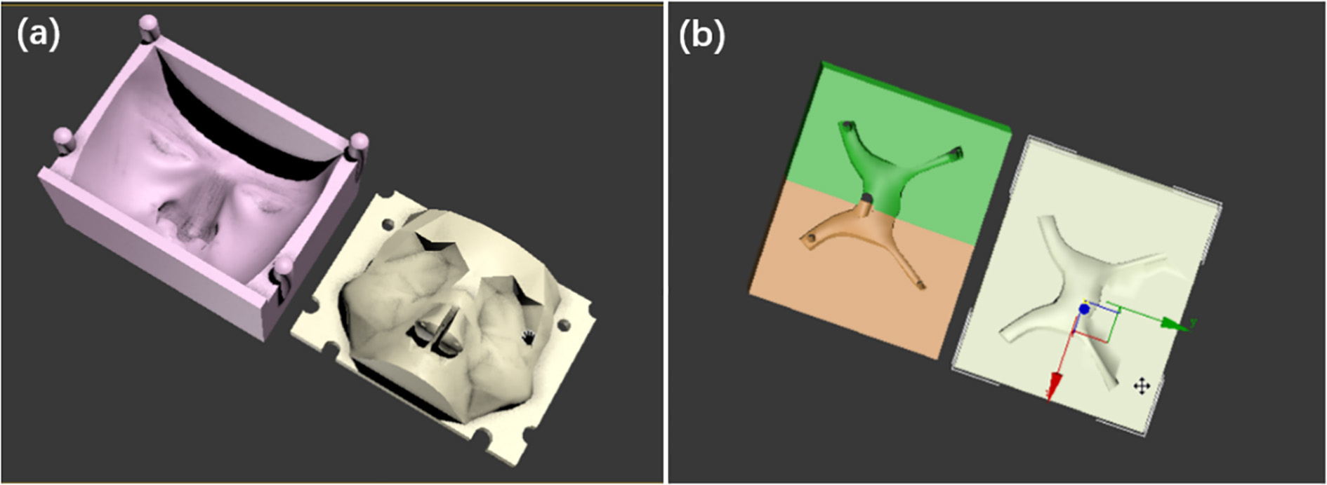
Note: (i) To pour the liquid into the mold, there should be a hole on the box. (ii) To take out the solid model, the mold should be detachable for at least two parts. (iii) The artery is a line so we should convert it to an editable polygon for the Boolean operation.
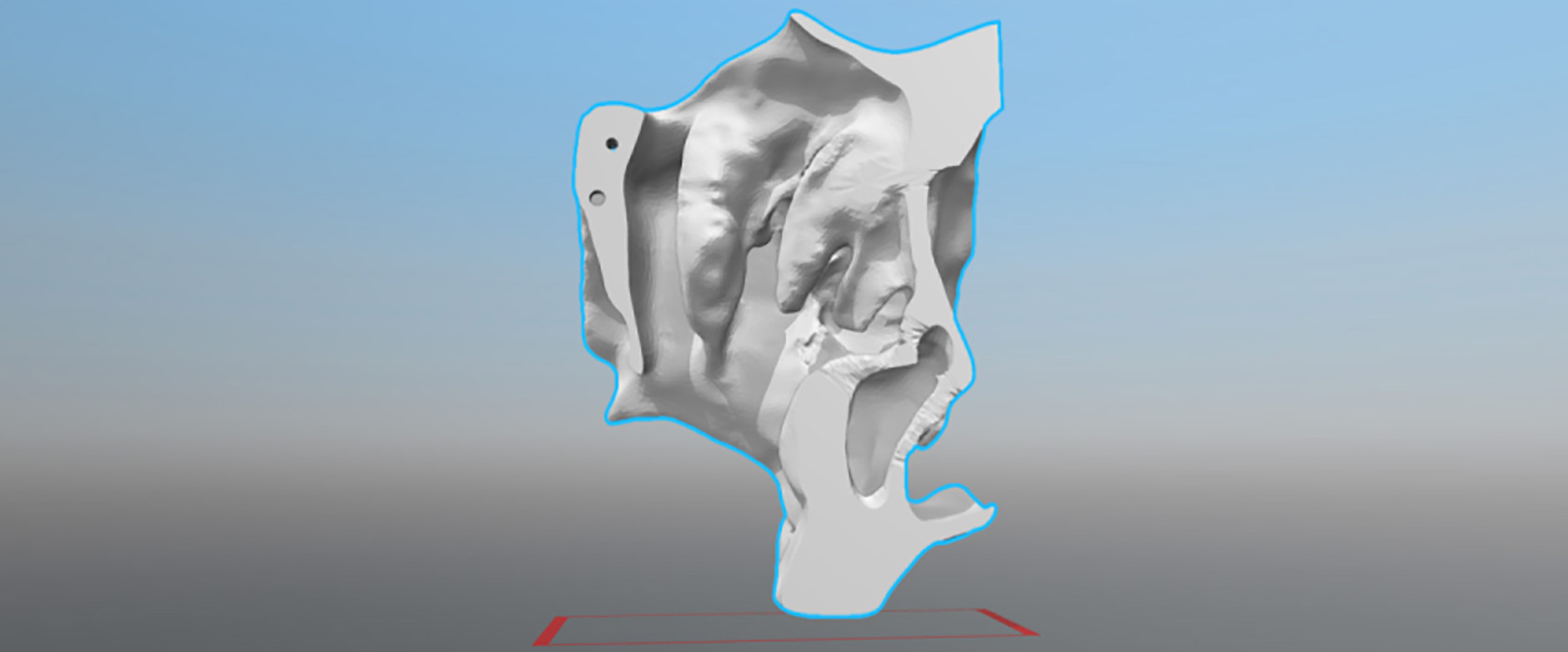
2.2.5The inner holes repairing
After slicing, the model may not be an enclosure, which cannot be printed. The top half and the bottom halves of the mold model are exported to Geomagic, which has an advanced function of filling holes.
Figure 14.
Fill up the holes. (a) The yellow shows that the model is not an enclosure. (b) Make a ‘Bridge’ between two edges of the hole. (c) Select the holes to fill. (d) Complete the filling.
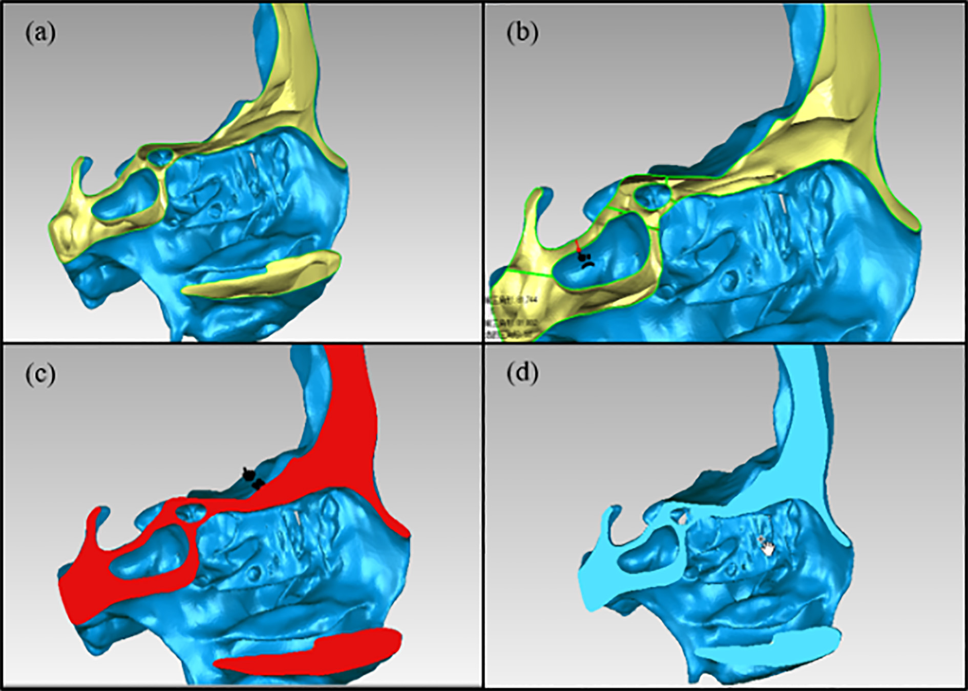
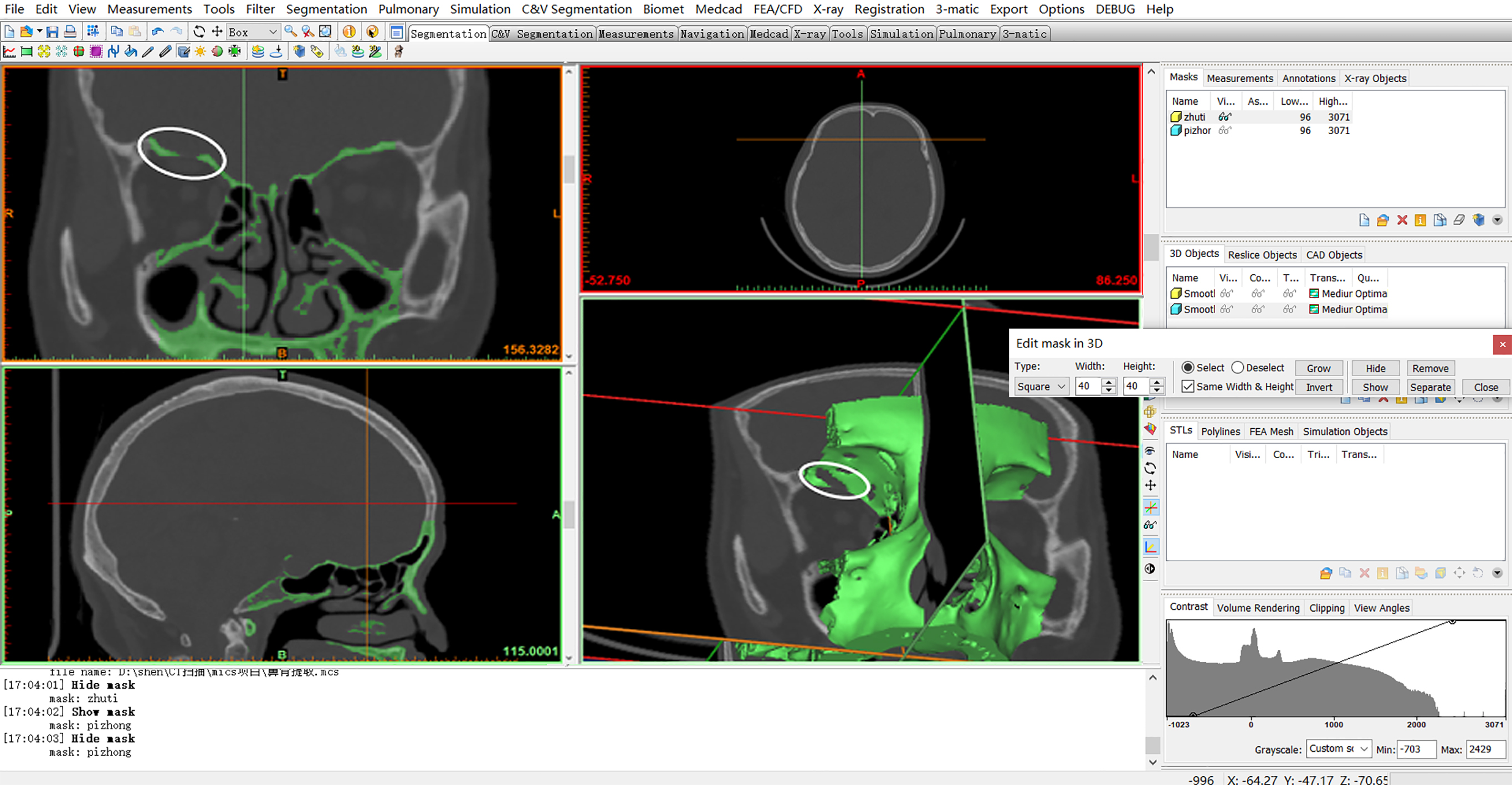
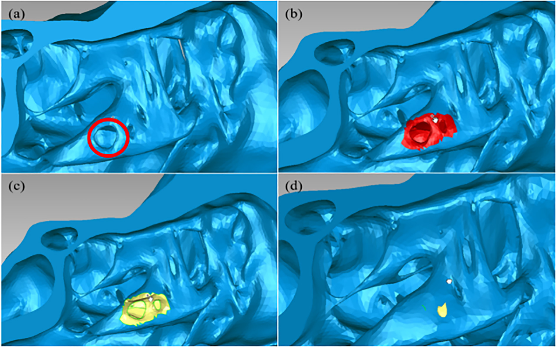
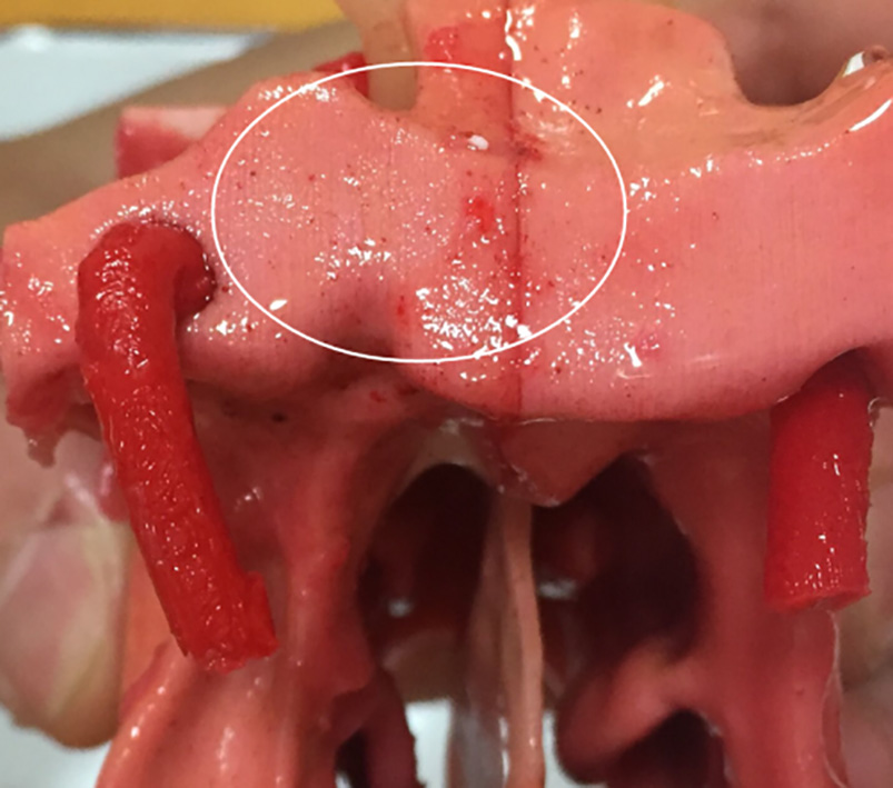
Figure 15.
Fix the hole in the surface. (a) A hole is circled in red. (b) The hole, as well as the surroundings, is selected. (c) Delete the selection to make it a recognizable hole for the software. (d) Select Fill Holes
The Geomagic Studio, owned by 3D System Inc., provides powerful 3D point cloud editing and advanced surfacing tools in an automated, user-friendly application. It has a very useful tool for filling the holes of the model.
Opening the digital model, we can see the obvious holes (in yellow) on the side due to the slicing (in Fig. 14a). Hence, we make it close by the following steps:
(a) Use Fill Holes
(b) Select Fill Holes
(c) Select the holes that need to be repaired (in Fig. 14c).
(d) The holes are filled up.
Using simple thresholding technique to distinguish compact bone and cancellous bone will produce some small holes on the surface of the model. Zooming in the model, some unexpected holes are still found inside the structure. An example can be found in Fig. 15.
2.2.6Triangular facets optimization
Once zoom to see the model, the triangular facets of the current model are disordered. For instance, some triangular facets are so close that they may make the quality of the printed model bad. The tools in ‘Polygons’ are helpful for improving the quality of the surface (Fig. 16). The surface is much smoother in Fig. 17. Finally, all prepared models, including the skull base, the molds and the surgical area are ready for printing.
Figure 16.
Improve the quality of model surface. Polygons
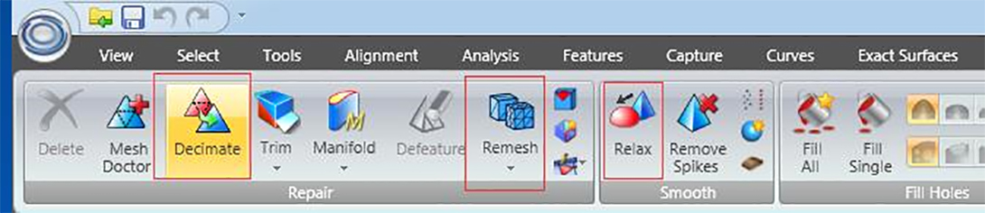
Figure 17.
The smoother surface of the left part of the surgical area.
2.3Summary of 3D image processing
For our endoscopic endonasal transsphenoidal pituitary surgery models, the problems in digital model processing and solutions are summarized in Table 1.
Table 1
Summary of main problems and corresponding solutions for the digital endoscopic endonasal transsphenoidal pituitary surgery model
| Problem | Cause | Solution | 3D manipulation tools | Tools |
|---|---|---|---|---|
| File format transformation | DICOM file cannot be edited directly | Upload the DICOM file and save it as STL file | Mimics (17.0) | File |
| Non-skull parts | The result of CT scanning includes all compositions of the head | Set the thresholding value Select the parts in 3D and delete them | Menu bar | |
| Missing structure | The limited accuracy of CT scanning and automatic threshold segmentation | Paint the parts slice by slice | Menu bar | |
| The surgical area should be printed by the breakable and low-cost material (plaster) | The sellar region will be broken during the surgery | Segment the skull | 3ds Max (2014) | Slice |
| Make internal carotid arteries, optic nerves and corresponding molds | The soft tissues should be protected carefully during the real surgery | Draw the objects and use Boolean operation | Compound Objects | |
| Wrong positions of holes | The limitation of CT scanning and automatic threshold segmentation | Fill the holes | Geomagic Studio (13.0) | Fill Holes |
| Inappropriate distribution of grids | The limitation of CT scanning | Analyze and optimize | Polygons |
3.3D model manufacturing
3.13D printing
Considering the accuracy requirements of the skull base and the molds, we choose a cost-efficient desktop 3D printer – Ultimaker2 with polylactide filament and fused deposition model method to print the skull base and molds. For the surgical area, in this study, 3D Systems ProJet 660 Pro with plaster and binder jetting method is used for printing. For the practice, the surgical area should be printed by the breakable and low-cost material (like plaster), as the sellar region will be broken during the real surgery.
3.2Making soft tissues (face, internal carotid arteries, pituitary and optic nerves)
The soft tissues might be obtained through 3D printing directly. However, the cost is high. In this case, we use molds, which are easier to print. First, smear the vaseline on the inner wall of the molds to help take out the model easily later. Second, mix different proportion of pigment and silica gel (simulation of human silicone) as face, pituitary, optic nerves and internal carotid arteries. The weight proportion of yellow pigment and silica gel is set as 0.01
Figure 18.
Small red dots, which look like capillaries.
3.3Building up the integral model
After building up all the parts of the model, we must process the surface of the surgical area part to make its texture close to the real. The operation is described as follows.
(a) Paint 5-degree silicone on the surface of the surgical area model to make the texture like skin.
(b) Pinch the turbinate off to simulate the situation during the surgery that the surgeon should stir the turbinate to insert surgical instruments into the nasal cavity. Please note that after the solidification, there is a malleable membrane on the surface. When we pinch the turbinate off, the broken parts will still be connected.
(c) Stick up two sides of nasal meatus and nasal septum with adhesive 502.
(d) Mount the internal carotid arteries, pituitary tumor and optic nerves onto their positions.
(e) Paint 0-degree silicone with a little red color paste. On one hand, since it is sticky, 0-degree silicone can be used to simulate the excretion in the nose, and, the red color with some red dots (shown in Fig. 18), which are diluted unevenly, can simulate capillaries in the nasal cavity and the sellar region. On the other hand, it can help fix the internal carotid arteries, the pituitary tumor and optic nerves.
Figure 19.
The complete surgical area. (a) Front. (b) Side. (c) Back.
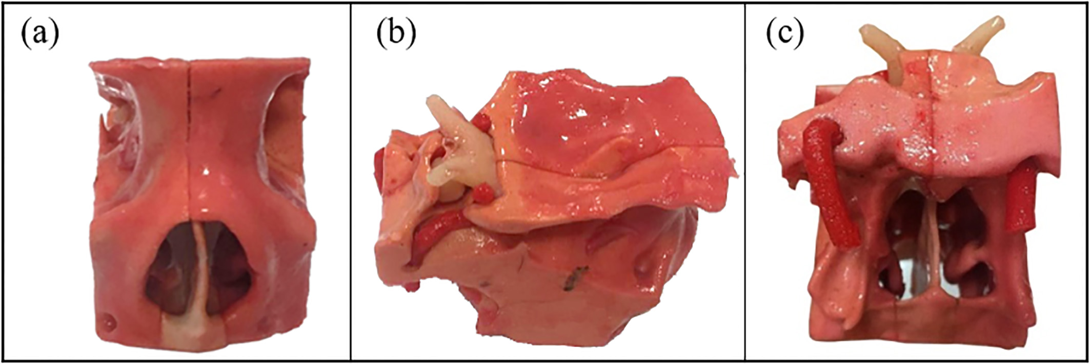
(f) Put the surgical area part onto the skull base (Fig. 19).
4.Results
The first part of the paper helps us obtain a digital 3D model for endoscopic endonasal transsphenoidal pituitary surgery. As shown in Fig. 20, the model contains all the structures and tissues involved in the real surgery which can be customized according to special requirements. Basically, the whole processing procedure can be implemented in the manufacturing process for other kinds of medical models. This process can be simplified as a general and standard case, which is shown in Fig. 21.
Figure 20.
Cutaway view of the digital model. (The surgical area contains the nasal cavity and the sellar region.)
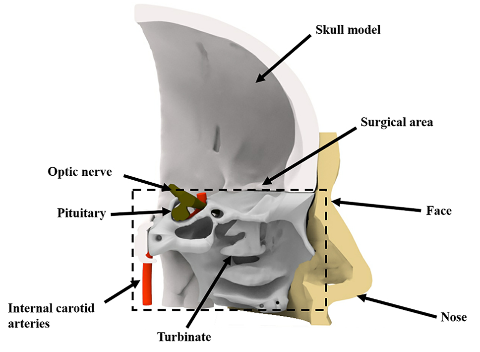
Figure 21.
A general procedure for the 3D printed medical model.
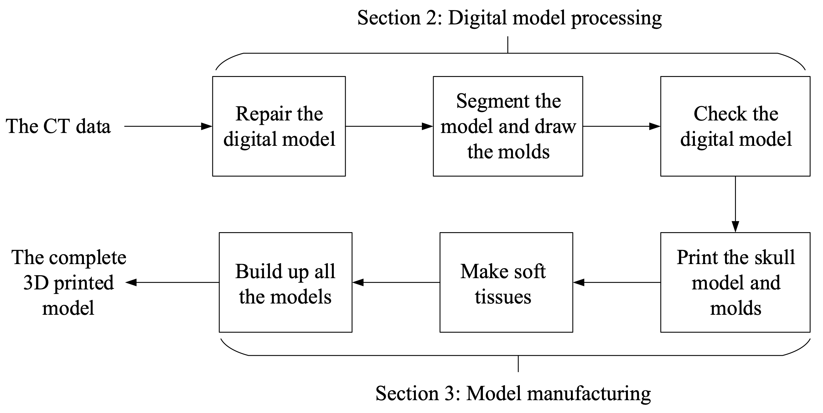
The main target of this procedure is to reduce the limitation caused by the inaccuracy of CT scanning and make the models ready for 3D printing. In addition, the influence of soft issues, like internal carotid arteries and optic nerves, which are obstacles and challenges during the real surgery, is considered.
Figure 22.
The complete model and the face.
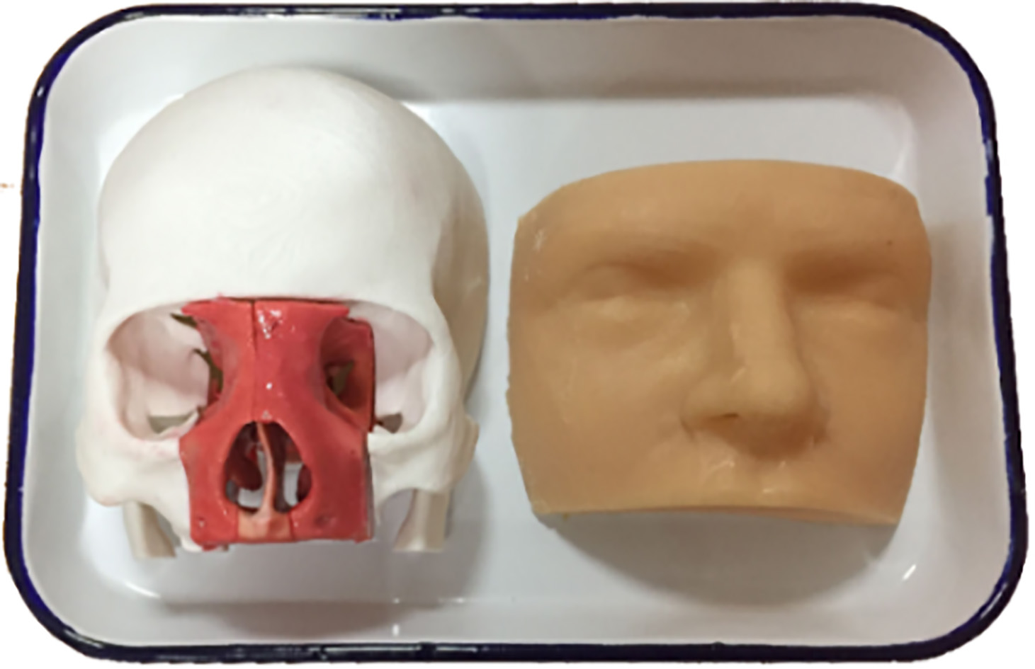
Finally, CT medical images have been successfully converted to correct digital models in the previous steps and till now, we produce printed models in 1:1 (Fig. 22) for hard structures (skull, nasal cavity and sinuses) and molds for soft tissues. We build up the whole model for the endoscopic endonasal transsphenoidal pituitary surgery. The weight of the model (excluding the face) is 260.767 g. Printing the skull base and molds by Ultimaker 2 takes 16 hours and printing one nasal cavity takes 3.5 hours by 3D Systems ProJet 660 Pro.
Figure 23.
Simulation of the endoscopic endonasal transsphenoidal pituitary surgery using a printed model. (a
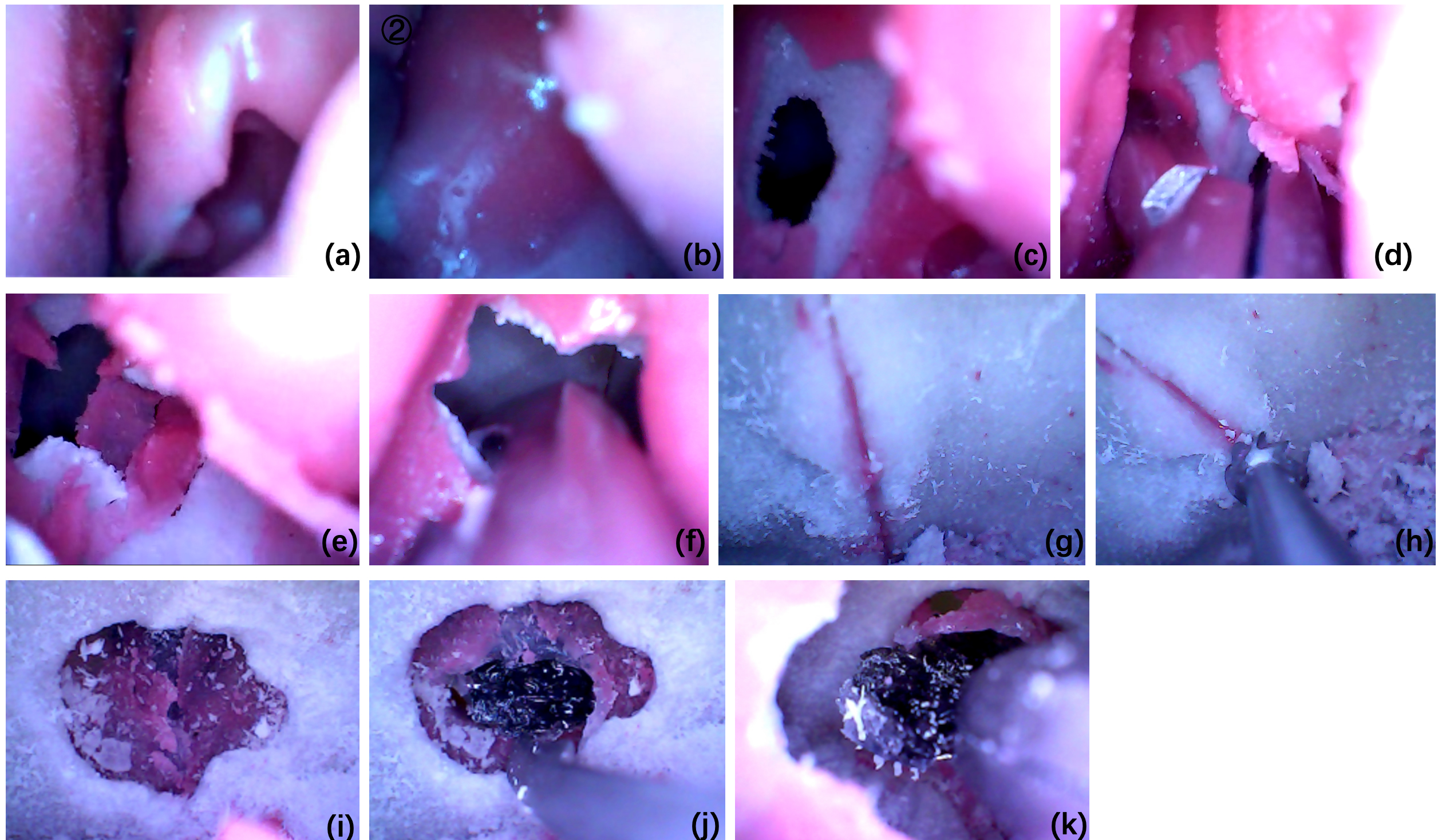
Furthermore, the printed model is used to simulate the real endoscopic endonasal transsphenoidal pituitary surgery and the result proves that the model works. The simulation of the surgery is shown in Fig. 23. The simulated procedure is the same as the real surgery.
5.Discussions and conclusions
Since the pituitary tumor is located near the internal carotid arteries and the optic nerves, the endoscopic endonasal transsphenoidal pituitary surgery is challenging, with a high risk of death and morbidity. For the adequate preparation and simulation, there should be “pituitary tumors”, “internal carotid arteries” and “nerves” in the model. Hence, we draw different invasion levels of pituitary tumors in 3ds Max, which are shown in Fig. 24.
Figure 24.
Different levels of tumors drawn in 3ds Max. (a) The tumor is bigger than the normal. (b) The tumor jacks up the optic nerve. (c) The tumor touches the internal carotid arteries. (d) The tumor wraps around some parts of the arteries. (e) The tumor surrounds the entire arteries.
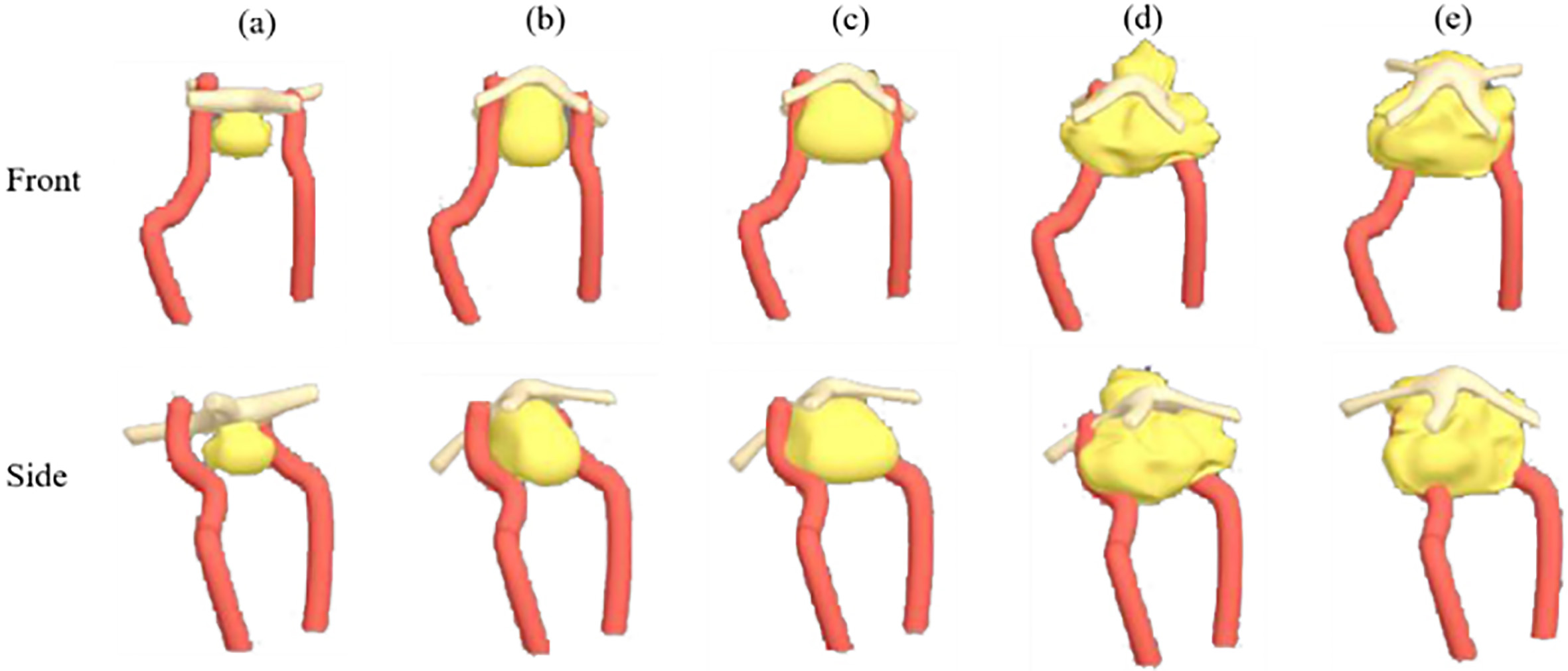
Figure 25.
Surgical area models with different levels of tumors.
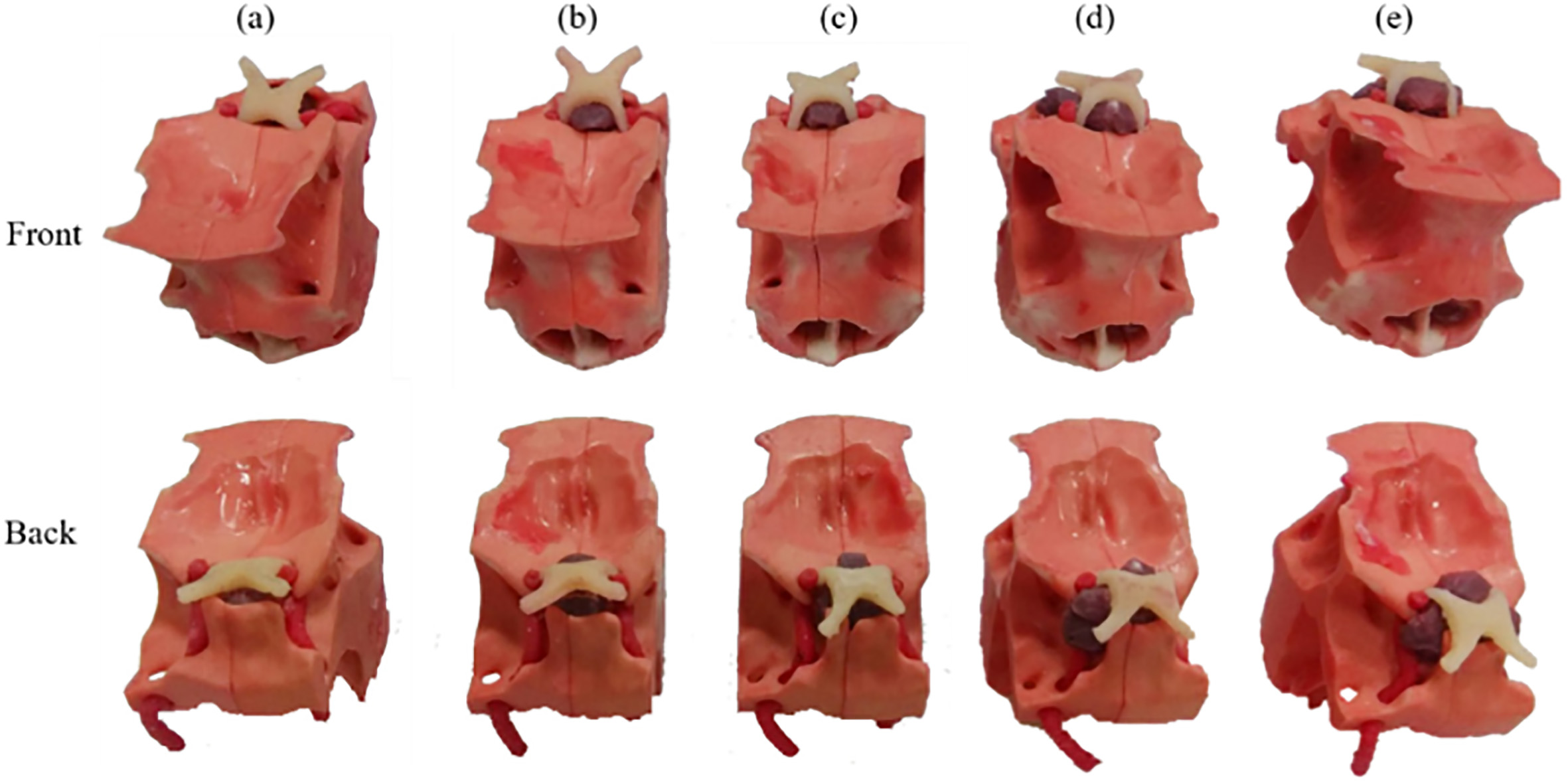
Like other soft tissues, we print the molds and pour the mixture of black pigment and silica gel to make the tumors. To simulate the situation that the pituitary tumor tops up the optic nerve, we set the tumor under the optic nerve and use adhesive 502 to stick them up. Subsequently, fix them with 0-degree silicone (shown in Fig. 25).
Through these models with different levels of tumors, neurosurgeons and medical students are able to do more targeted surgical simulations. Specifically, for those patients, the personal medical models can help analyze the conditions and make accurate plans for the surgery and therapy. With the assistance of 3D printed medical models, the surgery can be practiced repeatedly. The surgical safety can be improved and the risk of death and morbidity can be reduced. In addition, the 3D printed medical model can be a good tool for the patient or their family members to learn about the disease, the condition and the risk of the surgery, which can promote the communication between the patients and neurosurgeons.
The process shown in the paper can be repeated similarly to manufacture other 3D medical models. Even though the digital sources may not be suitable to print directly, the described operations can be helpful to fix the digital model and make the complete model with soft tissues. The process can be a normal and standard procedure in 3D medical model production. In previous research of Peking Union Medical College [25], the 3D printed skull model is used in a randomized controlled trial (RCT), for comparison of the learning effect of 3D printed skulls with that of cadaveric skulls and the atlas. The outcomes demonstrate that the 3D printed skull model is able to improve the structure recognition learning. This case proves that the 3D printed anatomical model is worthy of use. Obviously, the model for specific surgery is able to improve the understanding of students or neurosurgeons on the specific or special situations.
Furthermore, by converting virtual digital medical resources into the tactile models, 3D printing technology can play more important parts in other areas of neurosurgery [31], like individual skull repair, bio-printed internal carotid arteries for vascular grafts and individualized chemotherapy drugs or radioactive substances for the treatment of malignant nervous system tumors.
For the technical aspect, the digital model processing can be more automatic and intelligent. With the calibration, the original medical data can be corrected by one integrated manipulation tool or platform and can be reviewed easily via 3D projection technology.
However, there are still some limitations of 3D printing technology in the medical application: (i) the image processing procedure is complicated and takes a long time, which requires neurosurgeons and engineers working on it together; (ii) the accuracy of CT scanning technique is limited, which is 1 mm in this study [32].
In conclusion, this study presents the whole process of converting medical 3D data to the complete model with the skull, the nasal cavity, the pituitary tumor, the blood vessel and the optic nerves. With precise organ structures, the model can be reliably used for endoscopic endonasal transsphenoidal pituitary surgery preparation, including teaching, training and preoperative planning. The process is operable, efficient and effective, and also has great reference value for the production of other medical models.
Acknowledgments
The work was supported in part by the National Natural Science Foundation of China under Grants 61773382, U1909218, 61773381, 61872365 and U19B2029, CAS Key Technology Talent Program (Zhen Shen), Chinese Guangdong’s S&T Project 2017B090912001, Dongguan’s Innovation Talents Project (Gang Xiong), Hunan Province Science and Technology Program 2018GK1040, Capital Characteristic Clinic Project (Z141107002514051), Young Teacher Training Program (2014zlgc0721), Education Reform Program (2014zlgc0141), and Peking Union Medical College Hospital Young Teacher Training Program (2015zlgc0714).
Conflict of interest
The authors declare no competing financial interest.
References
[1] | Ezzat S, Asa SL, Couldwell WT, et al. The prevalence of pituitary adenomas: a systematic review. Cancer. (2004) ; 101: (3): 613-9. doi: 10.1002/cncr.20412. |
[2] | Kabil MS, Eby JB, Shahinian HK. Fully endoscopic endonasal vs. transseptal transsphenoidal pituitary surgery. min-Minimally Invasive Neurosurgery. (2005) ; 48: (6): 348-354. doi: 10.1097/01.wnq.0000173449.78221.3e. |
[3] | Lindert EJ, Grotenhuis JA. Endoscopic endonasal transsphenoidal surgery of pituitary tumors. Contemporary Neurosurgery. (2011) ; 33: (1): 1-8. doi: 10.1097/01.CNE.0000392953.27024.f5. |
[4] | Wikipedia contributors. Sinus (anatomy). Wikipedia, The Free Encyclopedia. Available from: https://en.wikipedia.org/w/index.php?title=Sinus_anatomy)&oldid=859197797. |
[5] | Jankowski R, Auque J, Simon C, et al. How I do it: Head and neck and plastic surgery: Endoscopic pituitary tumor surgery. The Laryngoscope. (1992) ; 102: (2): 198-202. doi: 10.1288/00005537-199202000-00016. |
[6] | Jho HD, Carrau RL. Endoscopy assisted transsphenoidal surgery for pituitary adenoma. Acta neurochirurgica. (1996) ; 138: (12): 1416-1425. doi: 10.1007/BF01411120. |
[7] | Cappabianca P, Alfieri A, De Divitiis E. Endoscopic endonasal transsphenoidal approach to the sella: towards functional endoscopic pituitary surgery (FEPS). MIN-Minimally Invasive Neurosurgery. (1998) ; 41: (2): 66-73. doi: 10.1055/s-2008-1052019. |
[8] | Gondim JA, Schops M, de Almeida JPC, et al. Endoscopic endonasal transsphenoidal surgery: surgical results of 228 pituitary adenomas treated in a pituitary center. Pituitary. (2010) ; 13: (1): 68-77. doi: 10.1007/s11102-009-0195-x. |
[9] | Fuchs KH. Minimally invasive surgery. Endoscopy. (2002) ; 34: (2): 154-159. doi: 10.1007/s11548-009-0327-9. |
[10] | Winkelmann A. Anatomical dissection as a teaching method in medical school: A review of the evidence. Medical Education. (2007) ; 41: (1): 15-22. doi: 10.1111/j.1365-2929.2006.02625.x. |
[11] | Hull CW. Apparatus for production of three-dimensional objects by stereolithography, U.S. Patent No. 4,575,330. Washington, D.C.: U.S. Patent and Trademark Office, (1986) . |
[12] | Friedman T, Michalski M, Goodman TR, et al. 3D printing from diagnostic images: A radiologist’s primer with an emphasis on musculoskeletal imaging – putting the 3D printing of pathology into the hands of every physician. Skeletal Radiology. (2016) ; 45: (3): 307-321. doi: 10.1007/s00256-015-2282-6. |
[13] | Yu DG, Zhu LM, Branford-White CJ, et al. Three-dimensional printing in pharmaceutics – promises and problems. Journal of Pharmaceutical Sciences. (2008) ; 97: : 3666-3690. doi: 10.1002/jps.21284. |
[14] | Yu DG, Branford-White C, Ma ZH, et al. Novel drug delivery devices for providing linear release profiles fabricated by 3DP. International Journal of Pharmaceutics. (2009) ; 370: (1-2): 160-166. doi: 10.1016/j.ijpharm.2008.12.008. |
[15] | Levy RA, Guduri S, Crawford RH. Preliminary experience with selective laser sintering models of the human temporal bone. American Journal of Neuroradiology. (1994) ; 15: (3): 473-477. doi: 10.1007/BF00588144. |
[16] | Cohen A, Laviv A, Berman P, et al. Mandibular reconstruction using stereolithographic 3-dimensional printing modeling technology. Oral Surgery, Oral Medicine, Oral Pathology, Oral Radiology, and Endodontology. (2009) ; 108: (5): 661-666. doi: 10.1016/j.tripleo.2009.05.023. |
[17] | Rengier F, Mehndiratta A, von Tengg-Kobligk A, et al. 3D printing based on imaging data: review of medical applications. International Journal of Computer Assisted Radiology and Surgery. (2010) ; 5: (4): 335-341. doi: 10.1007/s11548-010-0476-x. |
[18] | Sun W, Starly B, Nam J, Darling A. Bio-CAD modeling and its applications in computer-aided tissue engineering. Computer-Aided Design. (2005) ; 37: (11): 1097-1114. doi: 10.1016/j.cad.2005.02.002. |
[19] | Starly B, Fang Z, Sun W, et al. Three-dimensional reconstruction for medical-CAD modeling. Computer-Aided Design and Applications. (2005) ; 2: (1-4): 431-438. |
[20] | Sun W, Lal P. Recent development on computer aided tissue engineering – a review. Computer Methods and Programs in Biomedicine. (2002) ; 67: (2): 85-103. doi: 10.1016/s0169-2607(01)00116-x. |
[21] | Sun W, Darling A, Starly B, et al. Computer-aided tissue engineering: overview, scope and challenges. Biotechnology and Applied Biochemistry. (2004) ; 39: (1): 29-47. doi: 10.1042/BA20030108. |
[22] | Rose AS, Kimbell JS, Webster CE, Harrysson OLA, Formeister EJ, Buchman CA. Multi-material 3D models for temporal bone surgical simulation. Annals of Otology, Rhinology & Laryngology. (2015) ; 124: (7): 528-536. doi: 10.1177/0003489415570937. |
[23] | Viana JHM, Bartolo PJDS. New applications of three-dimensional data acquisition, modelling, and printing in animal sciences: A case report. Proceedings of the 2nd International Conference on Progress in Additive Manufacturing (Pro-AM 2016), 122-127. |
[24] | Shen Z, Yao Y, Xie Y, et al. The process of 3D-printed skull models for the anatomy education. Computer Assisted Surgery. (2019) ; 24: (Sup 1): 121-130. doi: 10.1080/24699322.2018.1560101. |
[25] | Chen S, Pan Z, Wu Y, et al. The role of three-dimensional printed models of skull in anatomy education: a randomized controlled trail. Scientific Reports. (2017) ; 7: : 575. doi: 10.1038/s41598-017-00647-1. |
[26] | Vincent L, Soille P. Watersheds in digital spaces: an efficient algorithm based on immersion simulations. IEEE Transactions on Pattern Analysis & Machine Intelligence. (1991) ; (6: ): 583-598. doi: 10.1109/34.87344. |
[27] | MaterialiseInc., Mimics Reference Guide 17, 0. 2017. |
[28] | AUTODESK. AUTODESK 3DX MAX 2016 HELP. [updated 2015; cited 2019 Sep 17] Available from: http//help.autodesk.com/view/3DSMAX/2016/ENU/. |
[29] | Wang XY, Jin ZH, Gan BW, et al. Engineering interconnected 3D vascular networks in hydrogels using molded sodium alginate lattice as the sacrificial template. Lab Chip. (2014) ; 14: (15): 2709-2716. doi: 10.1039/c4lc00069b. |
[30] | Mashiko T, Otani K, Kawano R, et al. Development of three-dimensional hollow elastic model for cerebral aneurysm clipping simulation enabling rapid and low cost prototyping. World Neurosurgery. (2015) ; 83: (3): 351-361. doi: 10.1016/j.wneu.2013.10.032. |
[31] | Shui W, Zhou M, Chen S, et al. The production of digital and printed resources from multiple modalities using visualization and three-dimensional printing techniques. International Journal of Computer Assisted Radiology and Surgery. (2017) ; 12: (1): 13-23. doi: 10.1007/s11548-016-1461-9. |
[32] | Fredieu JR, Kerbo J, Herron M, et al., Anatomical models: a digital revolution. Medical Science Educator. (2015) ; 25: (2): 183-194. doi: 10.1007/s40670-015-0115-9. |


