
Study on an actuation system development using temperature control of metal hydrides
Abstract
BACKGROUND:
Hydrogen storage using metal hydride (MH) offers various advantages so the global research and development using MH alloys keeps growing.
OBJECTIVE:
In this paper, we developed a new actuation system using temperature control of the MH module.
METHODS:
The actuation system consisted of an MH module, fan, mass flow controller (MFC), solenoid valve, actuator, and a temperature and pressure sensor. The MH module, two fans and temperature sensors were set for heating and cooling the MH power by electricity. Two MFCs and four pneumatic solenoid valves were used for controlling the direction and measuring hydrogen flow. Two actuators were used to evaluate performance of the MH alloy, and all the results were measured by LabVIEW software. Hydrogen was absorbed by the MH alloy by pressurizing at 1 MPa, and the absorbed hydrogen was desorbed using a vacuum pump.
RESULTS:
The temperature condition of the driving test was 20–50
CONCLUSION:
It is confirmed that the actuation system is suitable for the evaluation of characteristics of MH alloy. Future studies are planned to develop MH alloys and test the actual driving performance using this system.
1.Introduction
The global research and development efforts into various actuators and actuation systems using hydrogen absorption-desorption characteristics of metal hydride (MH) alloy keeps growing. Hydrogen storage and usage methods based on hydrogen absorption-desorption characteristics are as follows: when hydrogen pressure is higher than the hydrogen absorption, equilibrium pressure is applied on MH alloy, and the hydrogen molecules on the surface of MH alloy dissociate, causing hydrogen to be stored inside MH alloy in the form of hydrogen atoms. There are two methods for using the stored hydrogen: one is hydrogen desorption by decreasing the pressure inside the hydrogen storage container to below the hydrogen desorption equilibrium pressure and the other is hydrogen desorption by increasing the temperature of the alloy to cause the pressure inside the container to be higher than the hydrogen desorption equilibrium pressure [1]. It was determined that the second method would be most useful when making devices more compact, so this device was designed and developed based on this method.
Hydrogen storage using MH alloy offers various advantages. First, hydrogen does not produce pollutants during combustion. Second, hydrogen is an excellent energy storage medium, as well as a simple fuel that can easily transition into other forms of energy [2, 3]. Third, hydrogen equivalent to approximately 1,000 times the existing hydrogen gas volume can be safely compressed, stored, and used in MH alloy. When hydrogen is stored inside MH alloy, solid-state storage of gaseous hydrogen takes place on the hydrogen site of the metal in the form of a MH, and because these hydrogen atoms are stored without touching the Van der Walls radius of the hydrogen molecules, a large volume of hydrogen can be stored safely [3]. Hence, hydrogen storage using MH alloy offers the advantages of high hydrogen storage capacity per unit volume at room temperature, does not need a high-pressure or heat-insulating vessel, allows long-term storage, and is able to desorb high-purity hydrogen [4, 5].
Hydrogen storage using MH alloy attracts attention for use in hydrogen storage technology for mobile distributed power and has a high consumer acceptance with lower operating pressure than that of other storage methods when used indoors [6, 7]. Various types of driving systems have been developed using such MH alloys. Ino [8] used carbon fiber, aramid pulp, and LaNi
As mentioned, various systems using MH alloy have been developed and fundamental studies on changes in hydrogen absorption-desorption and heat transfer efficiency using each system have been conducted. However, not much data on quantitative analysis of the performance of driving systems using MH alloy are available. Therefore, the present study developed a driving system based on the hydrogen absorption-desorption characteristics of MH alloy according to heating and cooling and established a system that can quantitatively assess the driving system.
2.Methods
2.1System configuration
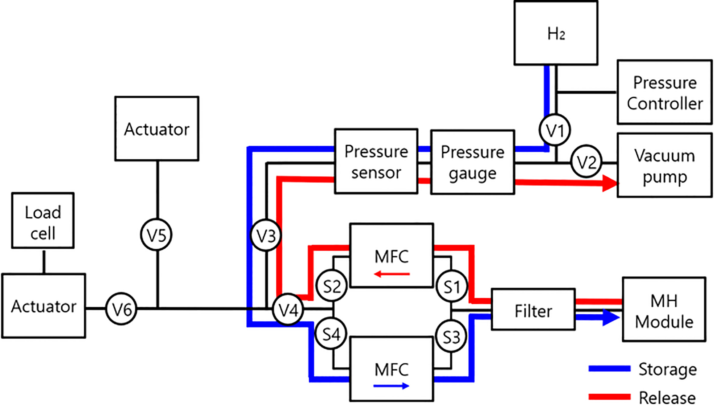
Figure 1 shows the block diagram of the driving system used for the recycling system. In the present study, electricity was applied to the Peltier elements within the MH module to desorb hydrogen by heating and cooling, which was then used to drive the actuator for assessment of the performance of the module. V1-6 and S1-4 shown in Fig. 1 represent valves used to control the flow of hydrogen; V1-6 are manually controlled and valves and S1-4 are pneumatic solenoid valves that can automatically open and close using nitrogen. Because the direction of hydrogen flow changes according to the changes in temperature applied to the MH alloy, pneumatic valves were used for precise identification and calculation of flow rate under heating and cooling conditions. For future precision experiments, all valves will be switched to pneumatic valves to automate the entire experimental process.
Figure 1.
Block diagram of the metal hydride actuation system.
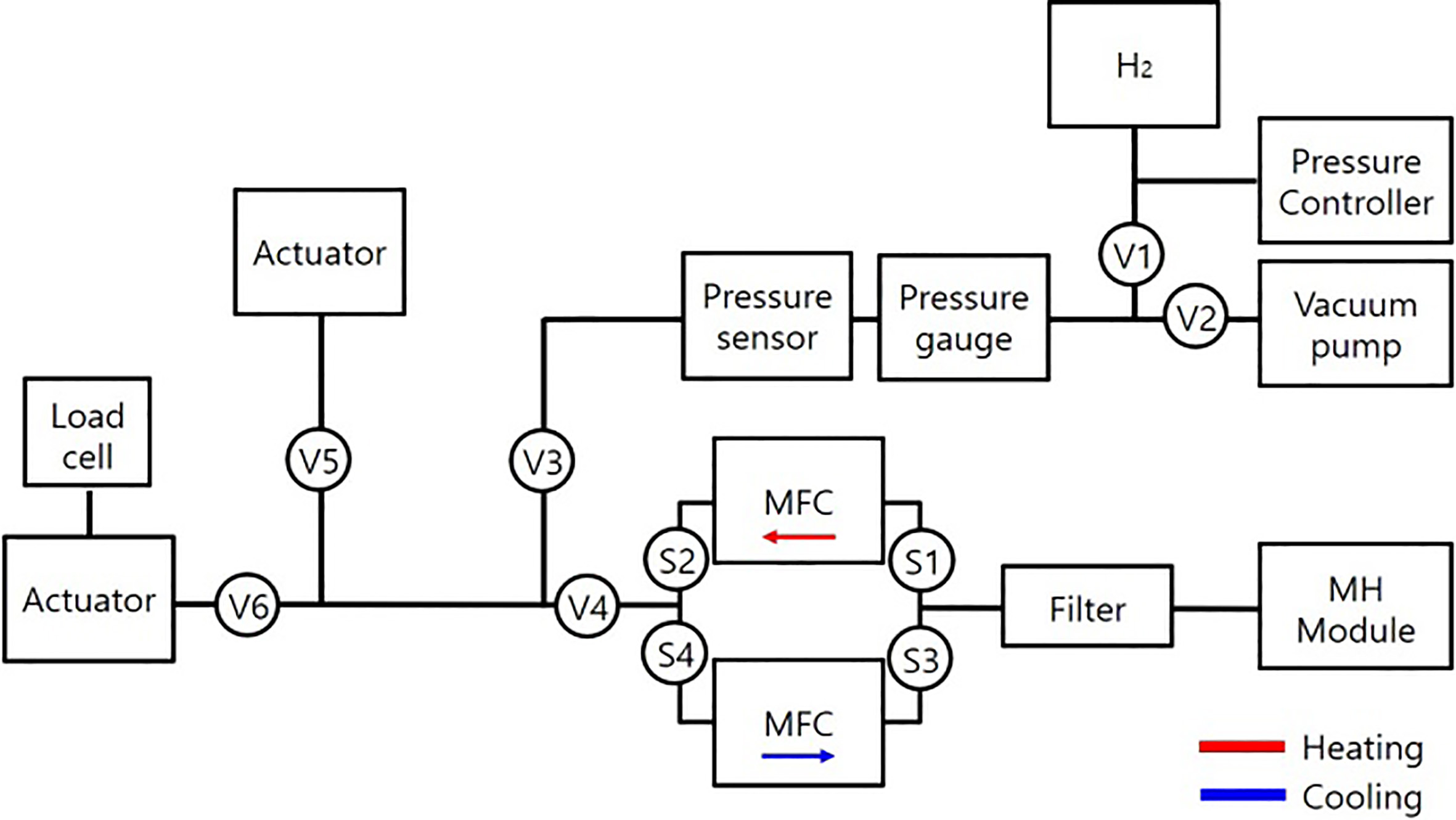
Figure 2.
Metal hydride actuation system.
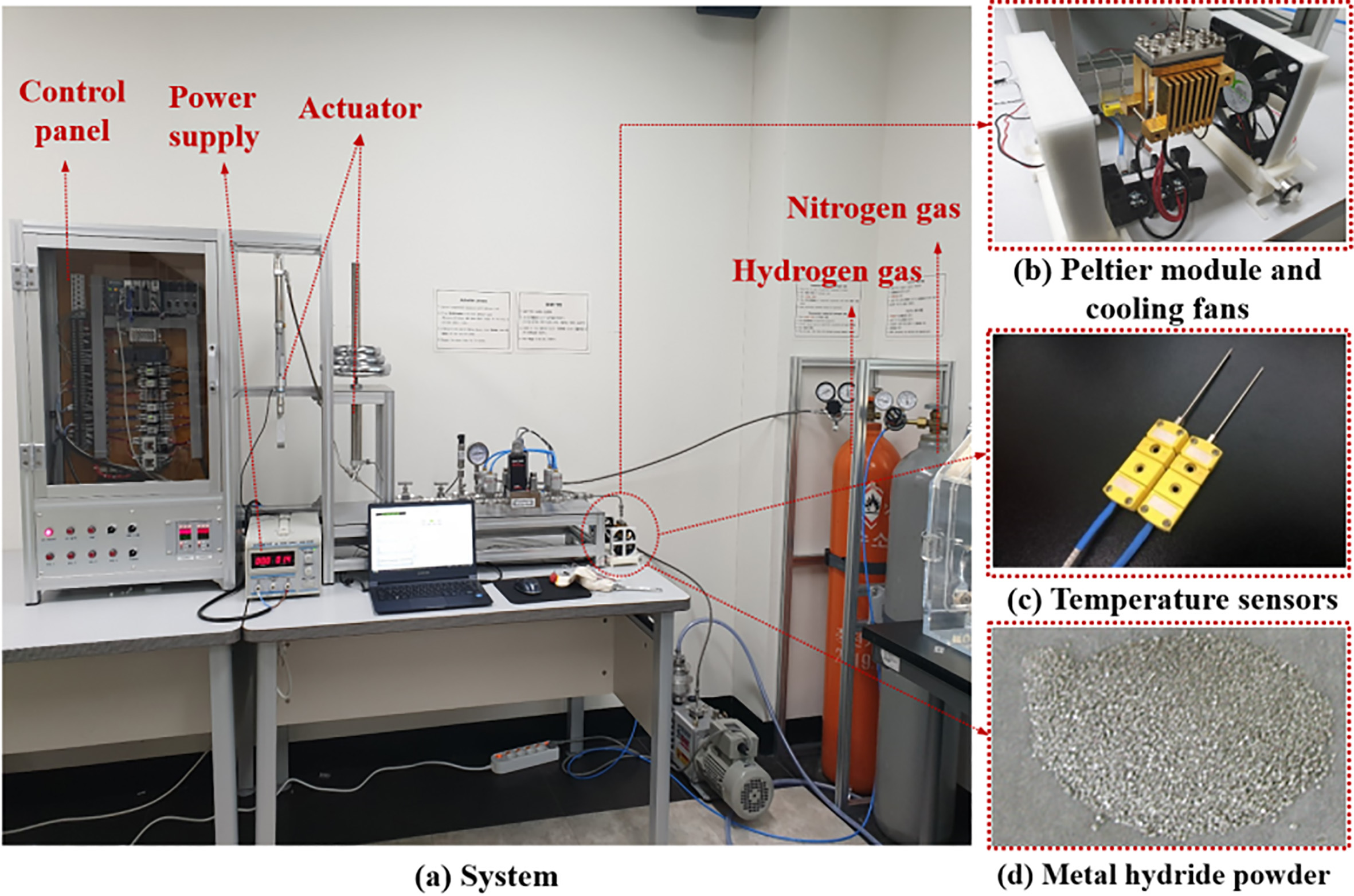
Figure 2a is a photograph of the driving system. In the MH module shown in Fig. 2b, two Peltier elements were loaded, after which, the power supply shown in Fig. 2a was connected to apply electricity to control the temperature of MH alloy inside the module. Two fans were placed on each side of the module to enhance the cooling effect. As shown in Fig. 2c, two temperature sensors were attached to the module for real-time measurement of changes in temperature of the module according to heating and cooling. Moreover, as shown in Fig. 2d, the inside of the module was loaded with MH powder (75–180
Figure 3 shows the MH module with the Peltier elements attached. Figure 3a is the sealing pad used to prevent gas leaks, and Fig. 3b shows the top and front views of the MH alloy charging unit. Figure 3c is a photograph of the entire module, and Fig. 3d is a photograph of the Peltier elements used for temperature control. To increase the cooling efficiency during cooling using the Peltier element, the outer surface of the module was fabricated as shown in Fig. 3c to increase the specific surface area. Hydrogen paths, as shown in Fig. 3e, were created to increase the efficiency of the MH alloy and shorten the activation time by facilitating the supply of hydrogen into the MH alloy.
Figure 3.
Metal hydride module with Peltier elements.
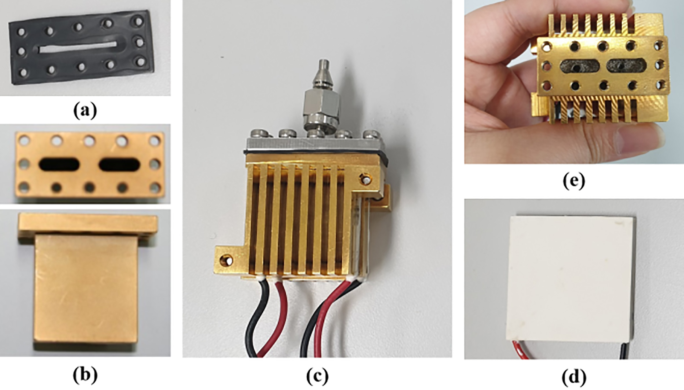
Figure 4.
Mass flow controller, pneumatic solenoid valves, pressure sensor and gauge.
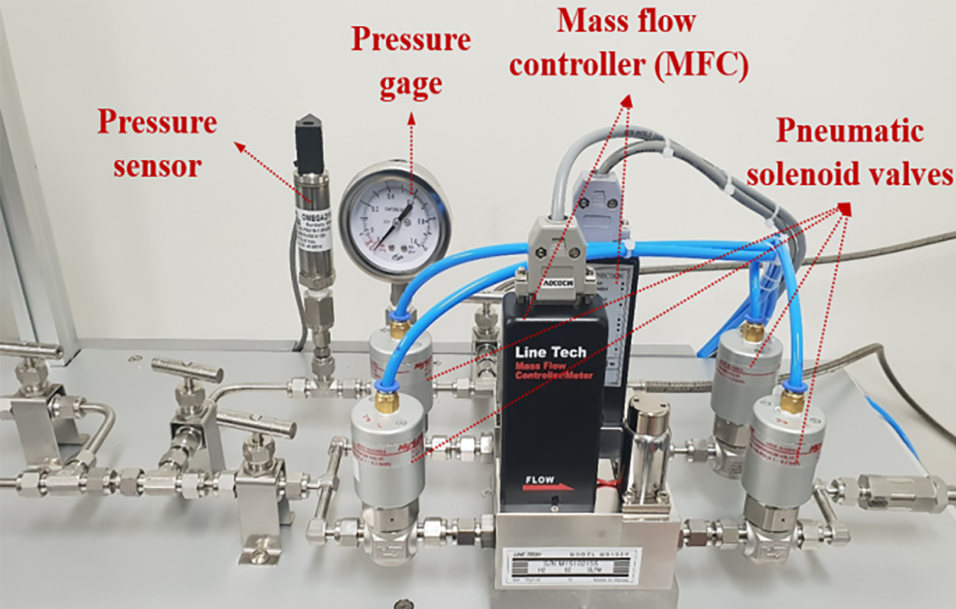
Figure 4 is an enlarged photograph of mass flow controllers (MFCs), pneumatic solenoid valve, pressure gauge, and pressure sensor shown in Fig. 2a. Two MFCs (M3100VA, Linetech) were used to control the amount of each hydrogen inflow and outflow from the MH alloy to maintain a constant level. The hydrogen flow control range was 0–60 SLPM, rated pressure was 1 MPa, and the allowable temperature range was 0–50
Figure 5.
(a) Control panel, (b) LabVIEW software for driving the system.
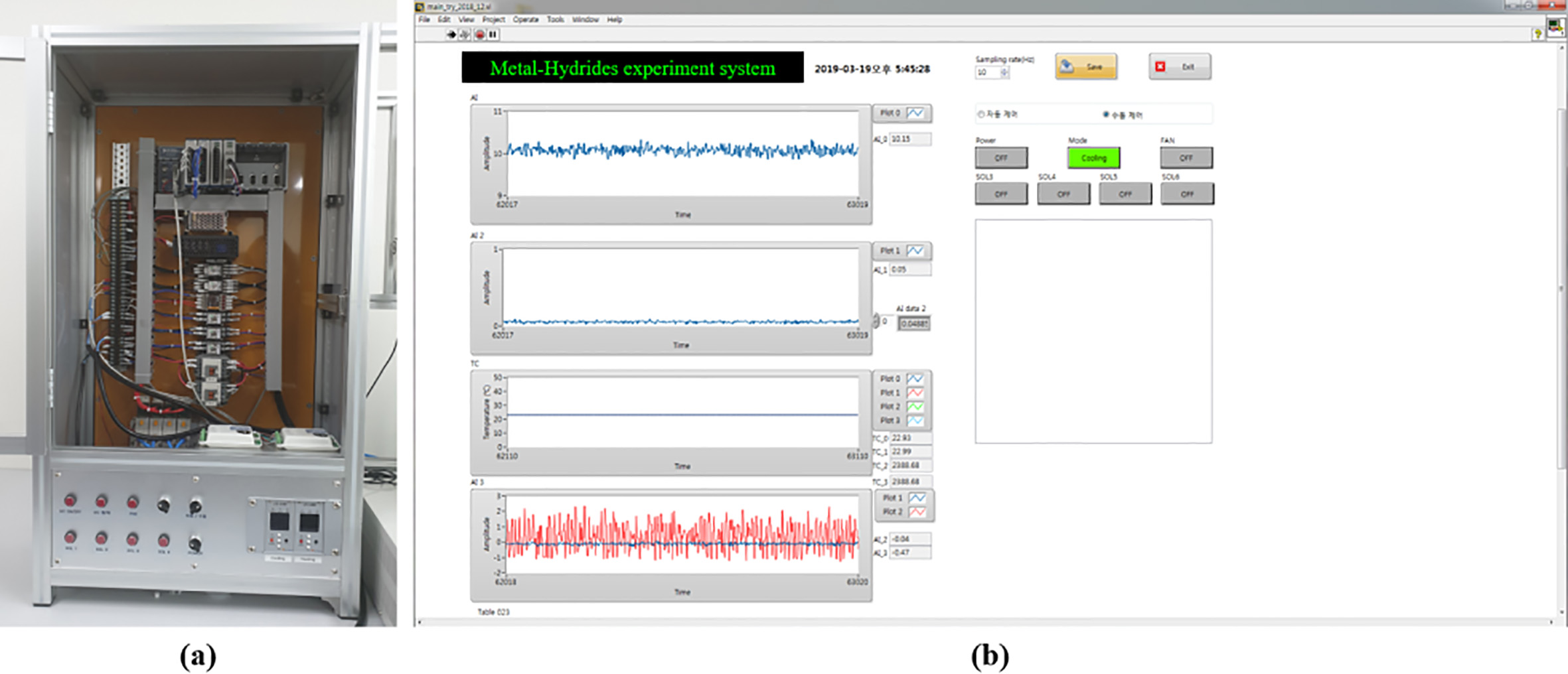
Figure 6.
Activation process of metal hydrides.
2.2Experimental method
In order to drive the system, it is necessary to store hydrogen inside the MH alloy through an activation treatment, while simultaneously removing impurities from the alloy and creating paths for inflow and outflow of hydrogen inside the alloy. The activation method involved opening the V1, V3, V4, S3, and S4 valves to introduce hydrogen into the module containing the alloy, followed by opening the V2, V3, V4, S1, and S2 valves and using a vacuum pump to expel any various impurities, including hydrogen, from the system. This process was repeated 3–5 times. The flow of hydrogen during the activation process can be found in Fig. 6.
Figure 7.
Movement of hydrogen by heating and cooling the metal hydride module.
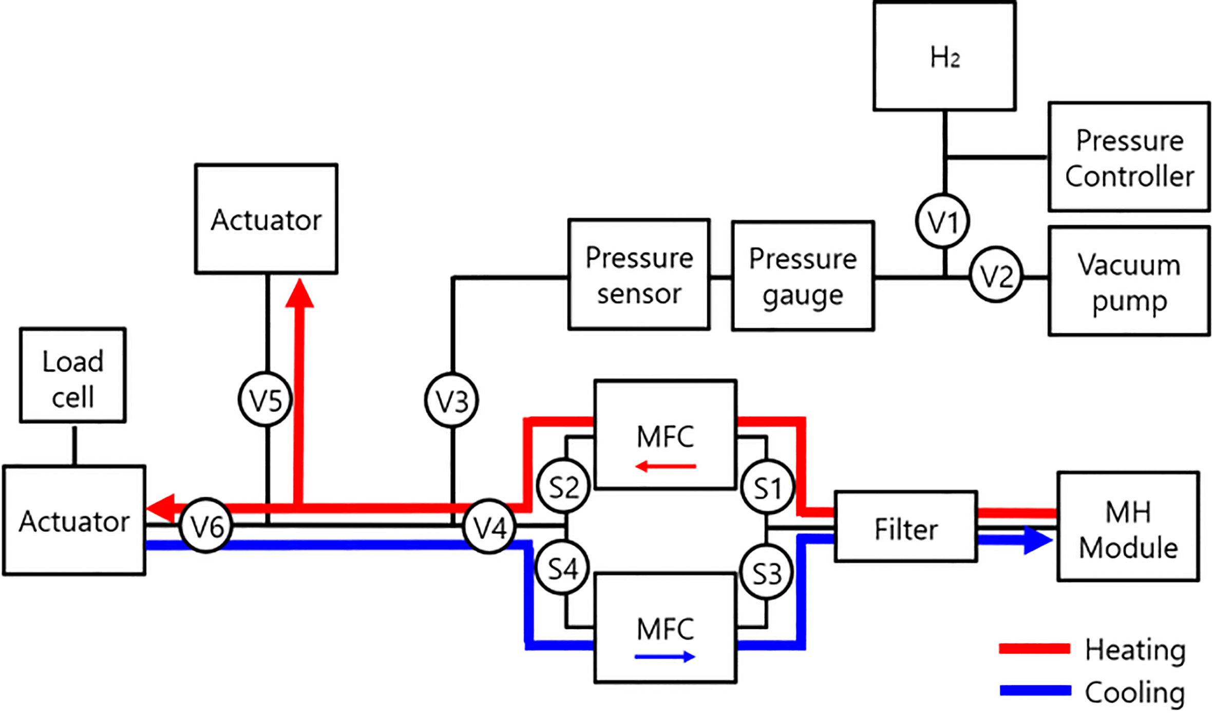
The assessment of the MH alloy module performance using the actuator involved actuation with repeated application of heating/cooling conditions, after which pressure, flow rate, and temperature of hydrogen inside the system were calculated by LabVIEW and the values were compared and analyzed to assess the actuator performance for each experimental condition. Under the heating condition, hydrogen could be desorbed by opening the V3, V4, S1, S2, V5, and V6 valves, while under the cooling condition, hydrogen could be absorbed or reabsorbed by the MH alloy by opening the V3, V4, S3, S4, V5, and V6. By repeating this process, assessment of module performance using hydrogen absorption-desorption characteristics is possible. The flow of hydrogen in the above described process can be found in Fig. 7.
3.Results
To test the driving performance of the MH actuation system, the actuation experiment was performed after activation using Zr
1) Prior to the activation treatment, soapy water was used to identify a possible hydrogen gas leak. After confirming that there was no hydrogen leak, the MH module containing the MH alloy was connected to the system. The connection between the module and system was checked for hydrogen gas leak.
2) After confirming that there was no hydrogen gas leak in the entire system, the valve connected to the hydrogen bomb was closed and the other valve connected to the vacuum pump was opened. Then the vacuum pump was used to create a state of vacuum inside the entire system.
3) After closing the valves connected to the vacuum pump, the hydrogen bomb was opened and the pressure controller was used to control the pressure of hydrogen gas inflow to 1 MPa. The valves connected to the system and the MFC in the direction of flow into the module were opened to introduce hydrogen into the module. When the pressure throughout the entire system reached 1 MPa, the valves connecting the system and hydrogen bomb were closed and soapy water was used again to check for hydrogen gas leak.
4) When the pressure inside the system dropped below 1 MPa, the MFC in the direction of flow into the module was closed and the MFC in the direction of flow out from the module was opened. Next, the valves connected to the vacuum pump were opened and the vacuum pump was run for approximately 40 minutes to create a state of vacuum inside the module, causing hydrogen absorbed on the MH alloy to be desorbed [15].
5) After the vacuum pump stopped running, the valves connected to the vacuum pump and MFC in the direction of flow out from the module were closed and step 3) was repeated.
6) After solid-state storage of hydrogen on MH by absorption was obtained using pressurization of hydrogen to 1 MPs, as described above, the vacuum pump was used to decompress the pressure inside the MH module, and the process of hydrogen desorption from the MH alloy using a vacuum was repeated four times.
The activation process was used for solid-state storage of hydrogen on the MH alloy inside the module. During the activation process, the inner pressure increased to about 1.1 MPa and the pressure decreased. The activation time tended to be shortened each time activation was repeated. Next, electricity was applied to the Peltier elements loaded inside the MH module with stored hydrogen to carry out a hydrogen desorption experiment. As the module was heated, it was confirmed that the actuator connected to the system was driven by the pressure of desorbed hydrogen from the MH module. The maximum temperature was set at 50
4.Discussion
In the present study, a driving system using temperature control was designed and developed. To control the temperature of MH alloy by applying electricity, two Peltier elements were attached (one in front and the other in the back). For efficient heating and cooling of the MH alloy module, two fans and a temperature sensor were set up. Two MFCs were set up to check and control the flow rate inside the module according to each process. Four pneumatic solenoid valves were used to control the direction flow according to heating and cooling conditions, while a pressure sensor and a pressure gauge were set up inside the module for precise pressure measurements during the experiment.
Furthermore, the use of two actuators allowed assessment of MH alloy performance under both heating and cooling conditions, while all values were measured and recorded via LabVIEW. Lastly, after absorption of hydrogen on Zr
Acknowledgments
This study was supported by the Basic Science Research Program through the National Research Foundation of Korea (NRF) funded by the Ministry of Education (no. 2018R1D1A3B07049251).
Conflict of interest
None to report.
References
[1] | Kang KK, Kang SS, Kwon HY, Lee RY. Fabrication and characteristics of 150ℓ class hydrogen tank using hydrogen storage alloy. Korea Hydrogen Energy Society. (2002) ; 13: (2): 110-118. |
[2] | Lee JW. Review: Hydrogen storage in solid state. Journal of the Korea Institute of Military Science and Technology. (2010) ; 13: (6): 1153-1171. |
[3] | Park CS, Kim JW, Bae KK, Jeong SU, Kang KS. Investigation of thermal management parameters of metal hydride based hydrogen storage system. Korean Hydrogen and New Energy Society. (2018) ; 29: (3): 251-259. |
[4] | Ino S, Sakaki K, Hosono M, Doi K, Shimada S, Chikai M. Application of metal hydride paper to simple pressure generator for use in soft actuator systems. Paper presented at: 37th Annual International Conference of the IEEE Engineering in Medicine and Biology Society; 25-29 Aug (2015) ; Milan, Italy. |
[5] | Noh SY, Rhee YW, Kang KS, Choi SJ, Kim JW. Technology characteristics of hydrogen storage and its technology trend by the patent analysis. Korean Hydrogen and New Energy Society. (2008) ; 19: (1): 90-102. |
[6] | Rusman NAA, Dahari M. A review on the current progress of metal hydrides material for solid-state hydrogen storage application. Hydrogen Energy. (2016) ; 41: (28): 12108-12126. |
[7] | Lototskyy MV, Tolj I. Pichering L, Sita C, Barbia F, Yartys V. The use of metal hydrides in fuel cell applications. Progress in Natural Science: Materials International. (2017) ; 27: (1): 3-20. |
[8] | Ino S, Sakaki K, Hosono M, Doi K, Shimada S, Chikai M. Application of Metal Hydride Paper to Simple Pressure Generator for Use in Soft Actuator Systems. Paper present at: 37thAnnual International Conference of the IEEE Engineering in Medicine and Biology Society (EMBC); 25-29 Aug (2015) ; Milan, Italy. |
[9] | Madaria Y, Kumar EA. Effect of heat transfer enhancement on the performance of metal hydride based hydrogen compressor. International Journal of Hydrogen Energy. (2016) ; 41: (6): 3961-3973. |
[10] | Lloyd GM, Kim KJ. Smart hydrogen/metal hydride actuator. International Journal of Hydrogen Energy. (2017) ; 32: (2): 247-255. |
[11] | Sato M, Yoshimura S, Hosono M, Yamashita K, Ino S. Development of a new portable rescue tool using metal hydride alloys. International Journal of Engineering Research and Development. (2017) ; 13: (5): 52-58. |
[12] | Obara S, Matsumura K, Aizawa S, Kobayashi H, Hamada Y, Suda T. Development of a solar tracking system of a nonelectric power source by using a metal hydride actuator. Solar Energy. (2017) ; 158: : 1016-1025. |
[13] | Park JM. A study on the hydrogenation characteristics of Zr-based Laves Phase Intermetallic Compounds [doctoral thesis]. [Daejeon]: Korea Advanced Institute of Science and Technology. (1990) ; 156. |
[14] | Kwon TK, Hong KJ, Kim K, Jeon WS, Pang DY, Lee SC, Kim NG. Development of SMH actuator system using hydrogen-absorbing alloy. Journal of Control,Automation and Systems Engineering. (2007) ; 13: (11): 1067-1073. |
[15] | Jeon WS. SMH actuator development and temperature-pressure characteristics using a peltier module [master’s thesis]. [Jeonju]: Chonbuk National University, (2004) , 69. |


