
A comparative study on the mechanical behavior of intervertebral disc using hyperelastic finite element model
Abstract
BACKGROUND:
Lumbar disc herniation may result in excruciating pain due to it being one of the most common diseases related to changes of intervertebral disc (IVD). In order to find a better clinical treatment and prevention scheme for relieving the pain caused by spine degeneration, the mechanical behavior analysis of IVD must be studied.
OBJECTIVE:
A finite element method (FEM) is used in this study to analyze the mechanical behaviors of healthy and herniated IVD.
METHOD:
In order to compare the responses of IVD under different loading conditions for the annulus fibrosus of IVD, the hyperelastic and elastic constitutive FE models were used in the FEM.
RESULTS:
The comparison shows that hyperelastic FE models have a much better capability to describe the mechanical behaviors of the IVD than elastic FE models. It can be found from FE simulation that there was a higher stress concentration at the annulus fibrosus of the herniated disc than the healthy disc.
CONCLUSIONS:
Higher stress concentration resulted in more damage and ease of bringing out lumbar disc herniation. Numerical examples of FE simulation indicate that the FEM with hyperelastic constitutive model has very good capability for analyzing the mechanical behaviors of IVD.
1.Introduction
Daily, human spines have the ability to perform a variety of motions and carry a considerable load during physical activities [1]. The intervertebral disc (IVD) plays an important part in the spine’s mobility. However, the IVD will generate a certain deformation of tension, compression, shear, bending, and torsion when the human conducts the daily physical activities. The age- and degeneration-related changes to the IVD are often observed with the increase in age [1]. Lumbar disc herniation is one of the most common diseases related to changes of the IVD. Pain is a common side effect of it, which can greatly impact quality of life, making it very important for the symptomatic patients to know how to relieve pain and improve function. Therefore, studies of spine changes are required to better understand the mechanism of degeneration of the aging spine in order to find more effective clinical treatment and prevention schemes.
As an efficient technique, finite element method (FEM) can be used to analyze the deformation and stress distribution of the aging spine. Because IVD distributes loads and provides motion and flexibility, it is the main component that effects the spine’s mechanical behavior. The main component of IVD is annulus fibrosus (AF) [2]. Therefore, the assumption of the constitutive model for the AF becomes one of the key steps in the finite element (FE) analysis. To study the behavior of IVD under axial loading, Belytschko et al. [3] firstly employed an axisymmetric FE model with linear orthotropic constitutive law for the AF. The results of this study presented the effects of material properties and geometry on the stress-distribution and intradiscal pressures. Goel et al. [4] used three-dimensional finite element model based on the fiber-reinforced concrete constitutive model for the AF in order to analyze the interlaminar shear stresses across the laminae of a ligamentous L3 and L4 motion segment. In order to describe the nonlinear anisotropic behaviors, a constitutive model for the AF was presented by Eberlein et al. [5]. They designed a new experimental procedure to determine the material parameters in the constitutive equations. FE analysis was carried out for intact lumbar disc bodies with the proposed constitutive model. Peng et al. [6] proposed an anisotropic hyperelastic constitutive model for the human AF based on fiber reinforced continuum. In their model, a three part strain energy function representing the anisotropic elastic material behavior is created: the energy contributions from the matrix, fiber, and fiber-matrix shear interaction. The partition of the strain energy function made it easy to determine the material parameters in the constitutive model. Based on the anisotropic hyperelastic constitutive model, FE models were developed by Park et al. [7] to analyze IVD degeneration effects on biomechanical behaviors of a lumbar motion segment under physiological loading conditions such as flexion, extension, lateral bending, and axial rotation movements. The results computed by the FE models agreed with previously published references. Schroeder et al. [8] developed the fibril reinforced poro-viscoelastic swelling model. It was used to describe the mechanical behaviors of the IVD subjected to a combination of elastic, viscous, and osmotic forces. The interaction of osmotic, viscous, and elastic forces in an IVD under axial compressive load was analyzed by the FEM based on the model. The numerical results revealed that tensile hoop stresses resulted from osmotic forces were higher than those in a non-osmotic disc. Fluid flows in and out of the disc during unloading and loading processes of the spine, resulting in osmotic pressure change. A poro-elastic finite element model [9, 10] was used to investigate the failure progression in a lumbar disc due to cyclic loading in order to better understand the effect of fluid flow on the biomechanics of the disc. Alterations of the disc’s geometry and the material properties were made. Due to this, a 3D nonlinear finite element model of the L3 and L4 functional spinal unit was used by Rohlmann et al. [11] to study the influence disc generation had on the mechanical behavior of the lumbar spine. In their study, disc height and bulk modulus of the nucleus pulposus were varied in order to simulate different grades of disc degeneration. They found that the mild disc degeneration increased intersegmental rotation for all loading cases and as the disc degeneration increased, intersegmental rotation decreased for flexion, extension, and lateral bending. Anterior lumbar interbody fusion (ALIF) is a type of surgery that can be used as treatment for degenerative disc disease, spondylolisthesis, spinal deformity, and pseudarthrosis [12]. By comparing three different grades of disc degeneration, Tang and Rebholz [12] also used the 3D nonlinear finite element model to analyze the biomechanical influence of the ALIF on the superior adjacent intervertebral disc. The study revealed that ALIF had a tendency to aggravate the adjacent upper segmental degeneration, resulting in an adverse biomechanical influence on the upper disc. The AF of the IVD is a complex structure composed of a solid porous matrix, saturated with water [13]. Cegoñino et al. [13] developed a constitutive model describing the poromechanical behavior of a porous material with osmotic pressure. FEM was used in their study to analyze the poromechanical behaviors. They found that the proposed model had the ability to simulate the poromechanical behavior of normal and degenerated AF.
To accurately describe the behavior of AF, complicated constitutive model is required. However, it is hard to determine vitro parameters if the parameters in the complicated model are too much. The constitutive behavior of a hyperelastic material is used to simulate the behavior of the AF. Many different constitutive models have been created for hyperelasticity, with the Neo-Hookean model being the most simple. The analysis of FEM [14] based on Neo-Hookean model was presented to study influence of the input parameters such as implant position, implant ball radius, presence of scar tissue, and gap size on intervertebral rotation, intradiscal pressure, and contact force in the facet joints. The Neo-Hookean model analyzed the effects of IVD degeneration on spine biomechanics based FEM under compressive forces and bending moments [7]. It was easier to determine the minimal parameters by using he Neo-Hookean model and numerical examples were used to prove the applicability of the model [7, 14].
Analyzing the mechanical behaviors of healthy and herniated IVD by using the FEM was the main objective of the present study. In order to compare the responses of IVD under different loading conditions, the specific hyperelastic (Neo-Hookean model) and elastic constitutive models were considered in the FEM. The numerical results reveal that mechanical behaviors of IVD are better described by hyperelastic FE models than elastic models.
2.Materials and methods
2.1Fundamental theory
As mentioned in Section 1, the hyperelastic constitutive model with less parameters was applicable to FE simulation. The FE analysis of AF in this work was based on the Neo-Hookean constitutive model for hyperelasticity. Reference [15] provides a detailed description of the Neo-Hookean constitutive model. This paper provides a summarization of the necessary concepts and equations for this study.
Given isotropic, incompressible, or almost incompressible hyperelastic materials, the strain energy potential in the form of the deviatoric and volumetric strain energy is given as
(1)
where
Setting
(2)
where
If set
(3)
This form is the simplest hyperelastic model, i.e., the Neo-Hookean model.
2.2Establishment of three-dimensional FE model of L4-L5 segment
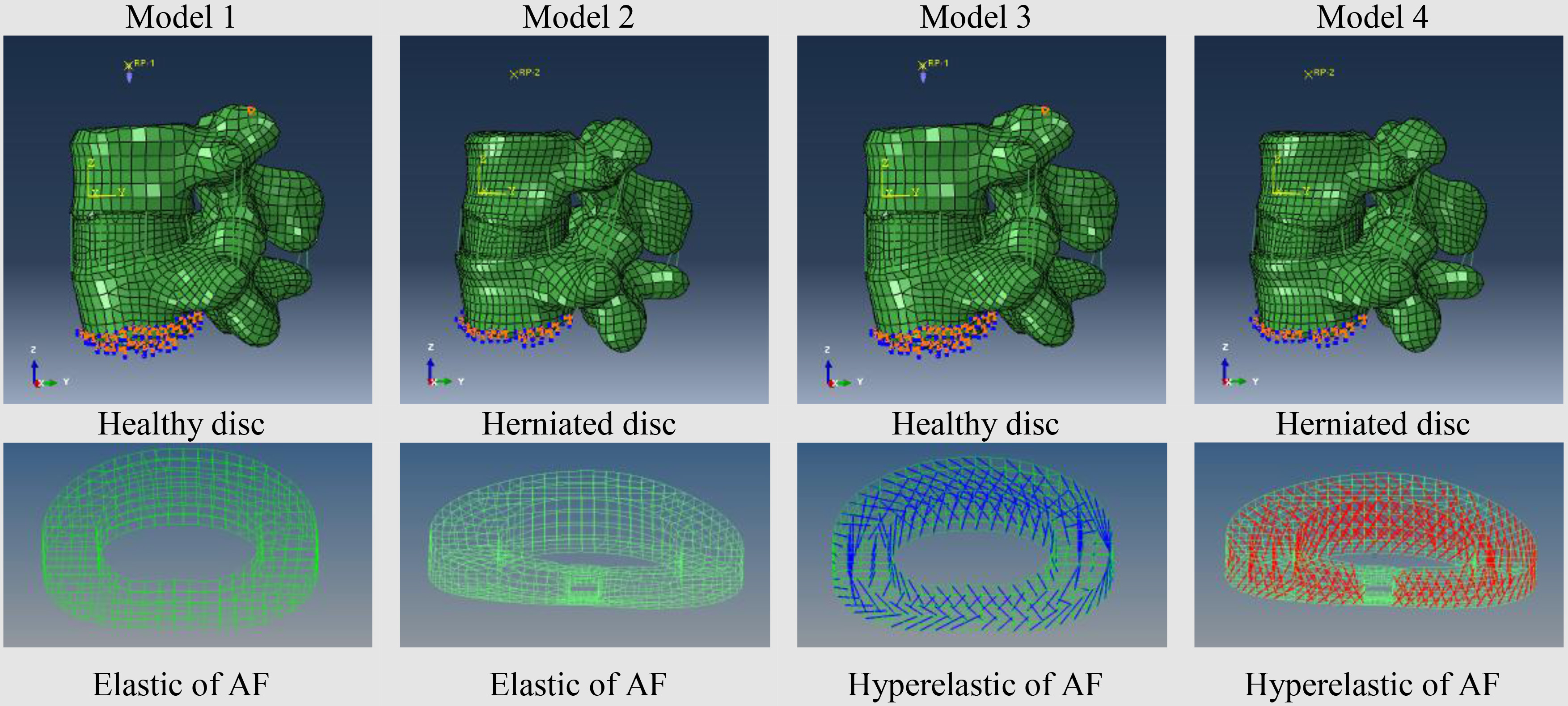
Figure 1 shows the four three-dimensional FE models of L4 and L5 segment that were established and the differences in material and geometrical properties between each model is show in Table 1. Annulus fibrosus and end endplate were the only differing material properties between healthy and herniated disc.
Table 1
Differences between four FE models
| Differences | Model 1 | Model 2 | Model 3 | Model 4 |
|---|---|---|---|---|
| Geometry | Healthy disc | Herniated disk | Healthy disc | Herniated disk |
| AF without fibers | AF without fibers | AF with fibers | AF with fibers | |
| Matireals | ||||
| Endplate | Elastic material | Elastic material | Hyperelastic material | Hyperelastic material |
| Ground substance | Elastic material | Elastic material | ||
| Collagen fibers | – | – |
Figure 1.
Four FE models of L4-L5 segment.
The main steps of FE model establishment are as follows:
Step 1 Scan 1.25 mm slice of C1 and S1segment with computed tomography from two male volunteers, one with a healthy disc (24 years old, 170 cm height) and the other with lumbar intervertebral disc herniation (35 years old,168 cm height).
Step 2 Subsequent to importing the data of CT’s into MIMICS 14.0 software, use 3D region growth, edit masks, Boolean calculating, etc. to construct the geometry model of L4 and L5 segment.
Step 3 Import the data of step two into Geomagic12.0 software for geometric smoothness, geometric surface repairing, etc. to obtain the geometric surface with IGES format by reverse processing.
Step 4 Use Solidworks2012 and knowledge of anatomy to reconstruct the intervertebral disc.
Step 5 Import the complete geometric model into Hypermesh12.0 software for ABAQUS pretreatment.
Step 6 Mesh partition. The vertebral model consists of the cortical bone, cancellous bone, and posterior structure. A shell element (S4R, 1 mm thick) was used to simulate the cortical bone wrapped in cancellous bone. IVD is composed of cartilaginous endplate, annulus fibrosus (collagen fibers and ground substance), and nucleus pulposus. Four layers of crossing fibers embedded in ground substance with the approximate cross angle of 30
Step 7 Each vertebral model was assigned a continuous, uniform, and isotropic material property.
2.3Material properties
Behavior differences between the normal disc and herniated disc were investigated by the four FE models show in Fig. 1. In order to make a contrast, while linear elastic material properties were assumed in models 1 and 2, nonlinear hyperelastic material properties (Neo-Hookean
Table 2
Material properties used in the FE models
| Components | Yong modulus | Poisson ratio | Components | Yong modulus | Poisson ratio |
|---|---|---|---|---|---|
| (MPa) | (MPa) | ||||
| Cortical bone | 12 000 | 0.3 | 1.0 | 0.1 | |
| Cancellous bone | 100 | 0.2 | Ligament | ||
| Posterior bony | 3500 | 0.25 | |||
| Cartilaginous endplate | 25 | 0.25 | Anterior | 7.8 | 0.3 |
| Annulus fibrosus | 92 | 0.45 | Posterior | 10 | 0.3 |
| Nucleus pulposus | 1.0 | 0.1 | Flavum | 15 | 0.3 |
| Hyperelastic for IVD | Interspinal | ||||
| | Supraspinal | 8 | 0.3 | ||
| | Intertransverse | 10 | 0.3 | ||
| | Capsular | 7.5 | 0.3 | ||
2.4Boundary and loading conditions
The surface of L4 and L5 segment end was selected as loading surface, and a reference point coupling with the nodes on L4 segment end was chosen as a loading point. In order to enable a FEM solution, some nodal displacements must be prescribed. It is assumed that all prescribed nodal displacements are prescribed as zero. Therefore, fixed-end constraints were applied as boundary condition at the nodes on L5 segment end. Guan et al. [19] validated a unique FE model of the lumbosacral junction (L4-L5, L5-S1) with rotation of a continuously moments from 0 Nm to 4 Nm under flexion, extension, and lateral bending. Their index rotation was compared with the data gathered by Panjabi et al.’s [20] experiment. According to a series of workshops, Wilke et al. [21] gave testing criteria for spinal implants. They suggested an amplitude took
In this study, the four FE models were first tested with pure unconstrained linear moments from 0 Nm–4 Nm under loading conditions of flexion, extension, lateral bending. Then in order to realize the four loading cases of flexion, extension, left lateral bending, and rotation of spine section in human activity, a pure moment of 7.5 Nm was successfully applied at the reference point. Axial loading of 500 N was applied in order to simulate human lumbar spine under compression.
3.Results and discussions
Based on the analysis of the FE post-processing results, the rotational stiffness of the vertebral body under four loading cases was obtained by calculating the range of motion (ROM) quotient, then divided by moments under a variety of bending conditions. Table 3 provides information regarding the rotational stiffness computed by the four FE models. It can be seen that the rotational stiffness values of hyperelastic FE models (models 3 and 4) were close to the experiment data in vitro [22], while the rotational stiffness values of elastic FE models (models 1 and 2) were much greater. This indicates that the hyperelastic FE model results agree better with experimental ones than elastic FE models. The stiffness values of flexion and lateral bending in model 4 were larger than those in model 3, while the stiffness values of axial rotation in model 4 were less than model 3. This indicates that the herniated disk has a decreased range of motion under flexion and lateral bending and an increase range of motion under axial rotation. This study’s results were consistent with those concluded by Mimura et al. [23].
Table 3
Rotational stiffness of four FE models under four loading cases
| Model 1 N | Model 2 N | Model 3 N | Model 4 N | Kanayama [22] | |
|---|---|---|---|---|---|
| Flexion | 9.099 | 8.356 | 0.778 | 0.844 | 0.8 |
| Extension | 18.31 | 16.150 | 2.567 | 2.526 | 0.8 |
| Left lateral bending | 15.214 | 17.984 | 1.391 | 2.024 | 0.5 |
| Rotation | 17.906 | 17.521 | 2.481 | 1.588 | 1.3 |
Figure 2.
Rotation of Flexion and extension under moments of 0 Nm–4 Nm.
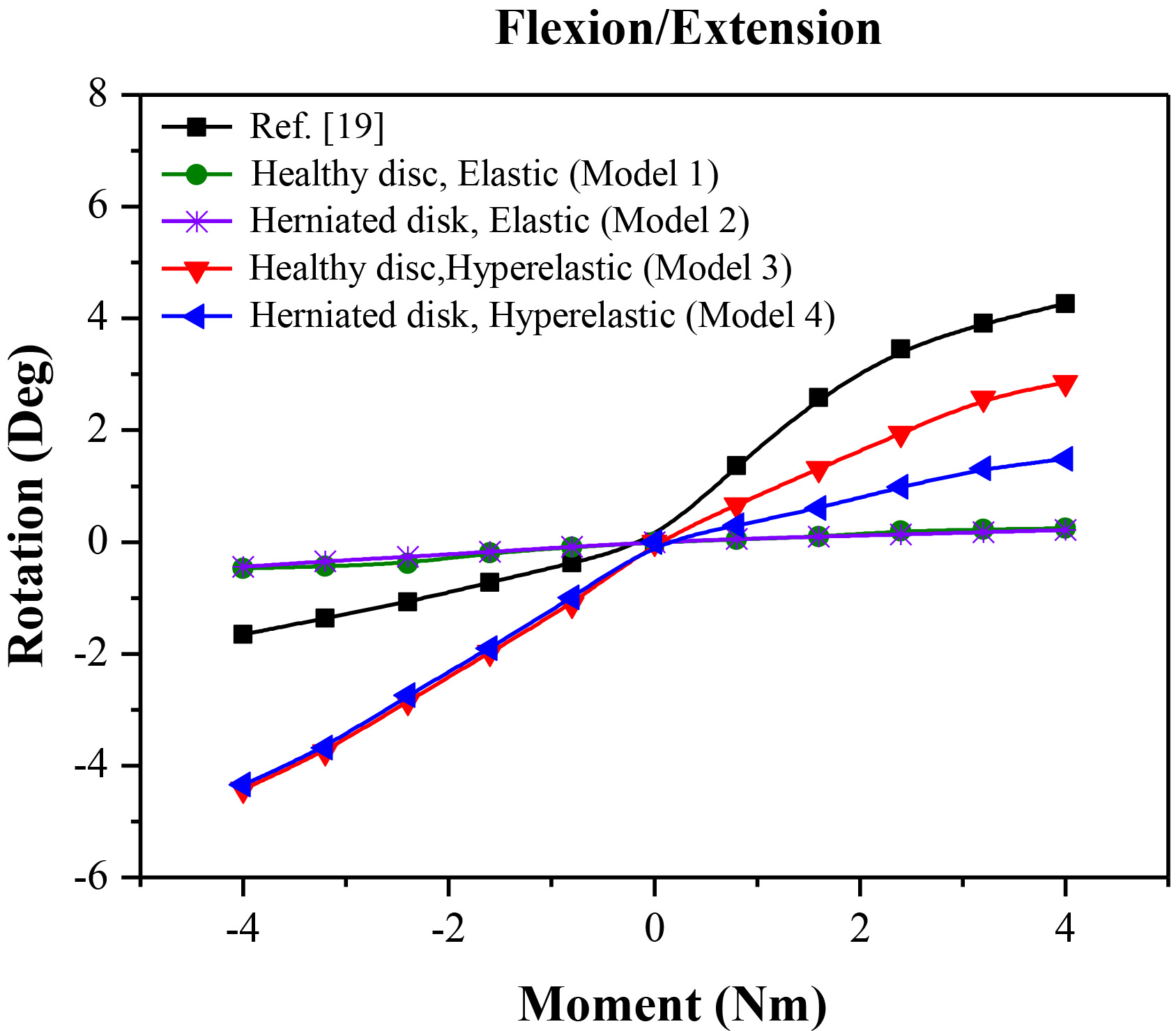
Figure 3.
Rotation of lateral bending under moments of 0 Nm–4 Nm.
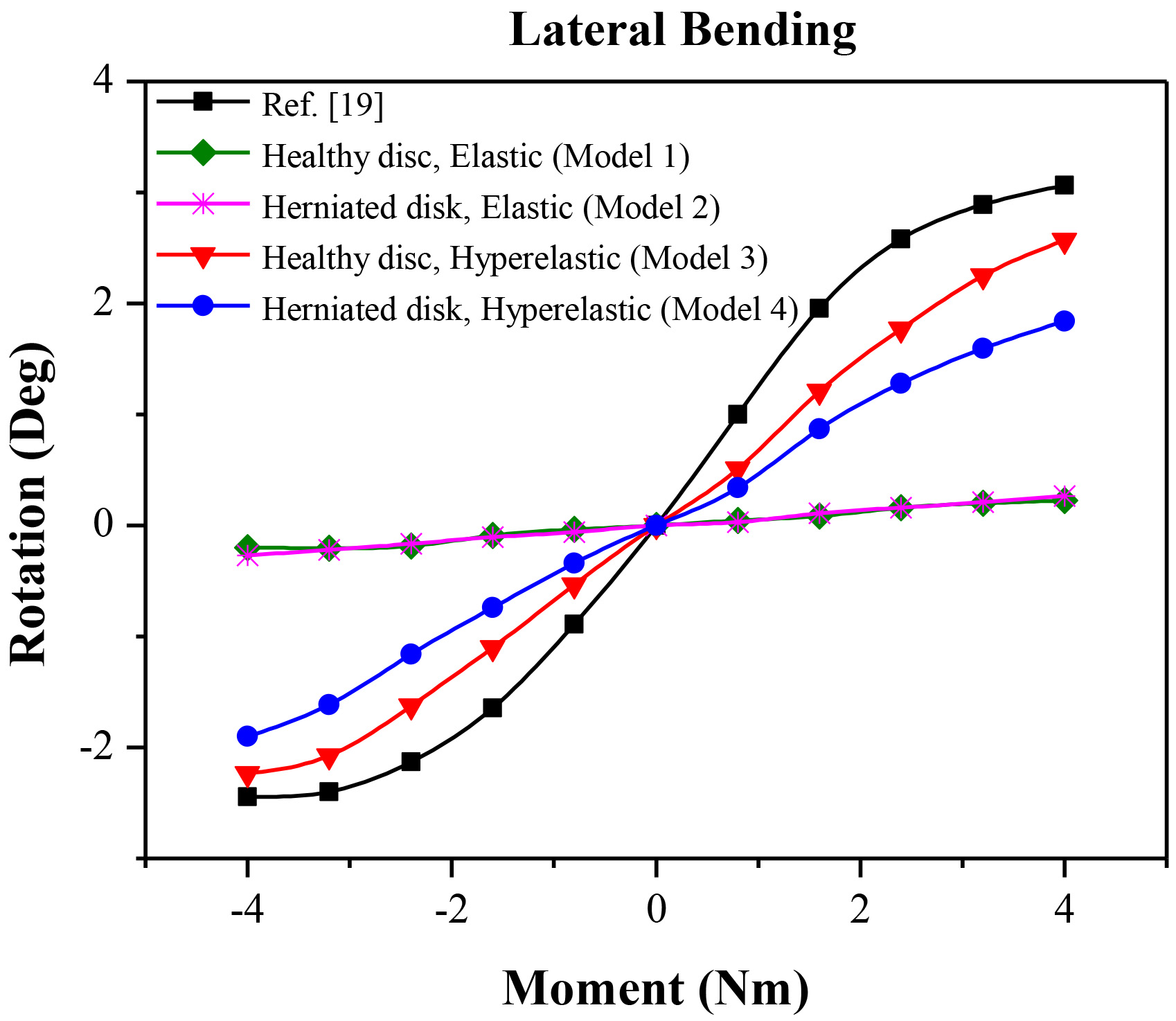
Figures 3 and 3 show the moment-rotation response curves with linear moments of 0 Nm to 4 Nm. The rotation response values of all elastic models (models 1 and 2) were much smaller than those of Refs. [19]. Compared with the results of Refs. [19], the moment-rotation response of the two hyperelastic models were greater in the case of flexion loading (minus moment) and smaller in the cases of lateral bending and extension loading (plus moment). Figure 4 presented the rotation results of four FE models under 7.5 Nm moments with 500 N compressive load. In comparison to elastic models, the results obtained by hyperelastic models were in better agreement with published data [7, 24].
Table 4
Peak displacement and von Mises stress under flexion
| Model 1 | Model 2 | Model 3 | Model 4 | |
|---|---|---|---|---|
| Stress of annulus fibrosus (MPa) | 2.384 | 2.258 | 2.487 | 1.151 |
| Stress of nucleus pulposus (MPa) | 0.021 | 0.058 | 0.248 | 0.663 |
| Displacement of annulus fibrosus (mm) | 0.247 | 0.257 | 3.241 | 2.989 |
| Stress of facet joint (MPa) | 0.811 | 0.633 | 0.774 | 0.510 |
Table 5
Peak displacement and von Mises stress under extension
| Model 1 | Model 2 | Model 3 | Model 4 | |
|---|---|---|---|---|
| Stress of annulus fibrosus (MPa) | 0.988 | 0.992 | 0.379 | 0.410 |
| Stress of nucleus pulposus (MPa) | 0.015 | 0.031 | 0.169 | 0.211 |
| Displacement of annulus fibrosus (mm) | 0.183 | 0.193 | 2.411 | 2.075 |
| Stress of facet joint (MPa) | 5.004 | 3.195 | 11.42 | 5.130 |
Table 6
Peak displacement and von Mises stress under lateral bending
| Model 1 | Model 2 | Model 3 | Model 4 | |
|---|---|---|---|---|
| Stress of annulus fibrosus (MPa) | 1.590 | 1.041 | 1.073 | 0.696 |
| Stress of nucleus pulposus (MPa) | 0.018 | 0.012 | 0.241 | 0.238 |
| Displacement of annulus fibrosus (mm) | 0.175 | 0.149 | 2.362 | 1.703 |
| Stress of facet joint (MPa) | 1.923 | 3.682 | 3.715 | 4.380 |
Figure 4.
Rotation of four FE models under 7.5 Nm moments with a compressive load of 500 N.
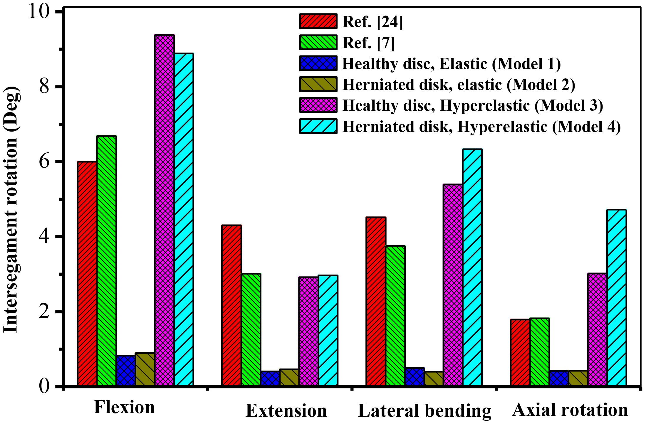
Table 7
Peak displacement and von Mises stress under rotation
| Model 1 | Model 2 | Model 3 | Model 4 | |
|---|---|---|---|---|
| Stress of annulus fibrosus (MPa) | 1.066 | 1.088 | 0.510 | 0.651 |
| Stress of nucleus pulposus (MPa) | 0.018 | 0.021 | 0.252 | 0.322 |
| Displacement of annulus fibrosus (mm) | 0.164 | 0.185 | 2.500 | 2.759 |
| Stress of facet joint (MPa) | 4.102 | 3.225 | 13.03 | 4.712 |
Table 8
Peak displacement and von Mises stress under compression
| Model 1 | Model 2 | Model 3 | Model 4 | |
|---|---|---|---|---|
| Stress of annulus fibrosus (MPa) | 0.264 | 0.067 | 0.294 | 0.268 |
| Stress of nucleus pulposus (MPa) | 0.016 | 0.010 | 0.134 | 0.114 |
| Displacement of annulus fibrosus (mm) | 0.095 | 0.011 | 1.417 | 1.204 |
| Stress of facet joint (MPa) | 1.001 | 0.577 | 0.976 | 0.705 |
Figure 5.
Stress and displacement distribution under compression.
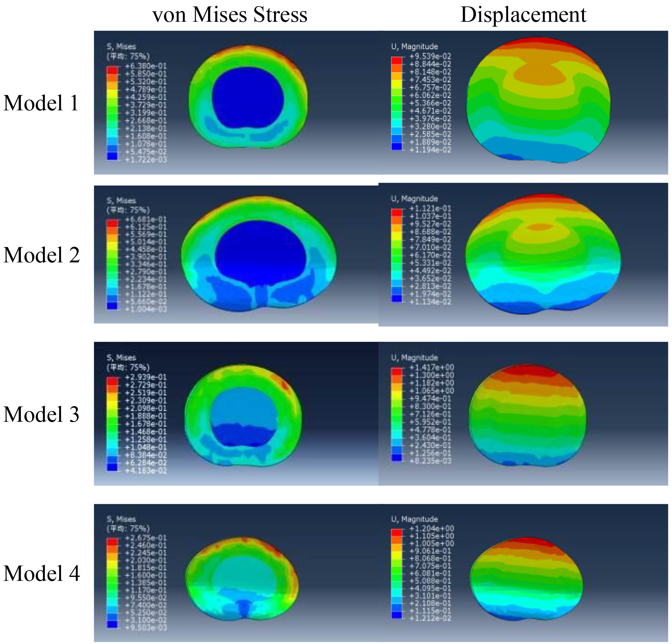
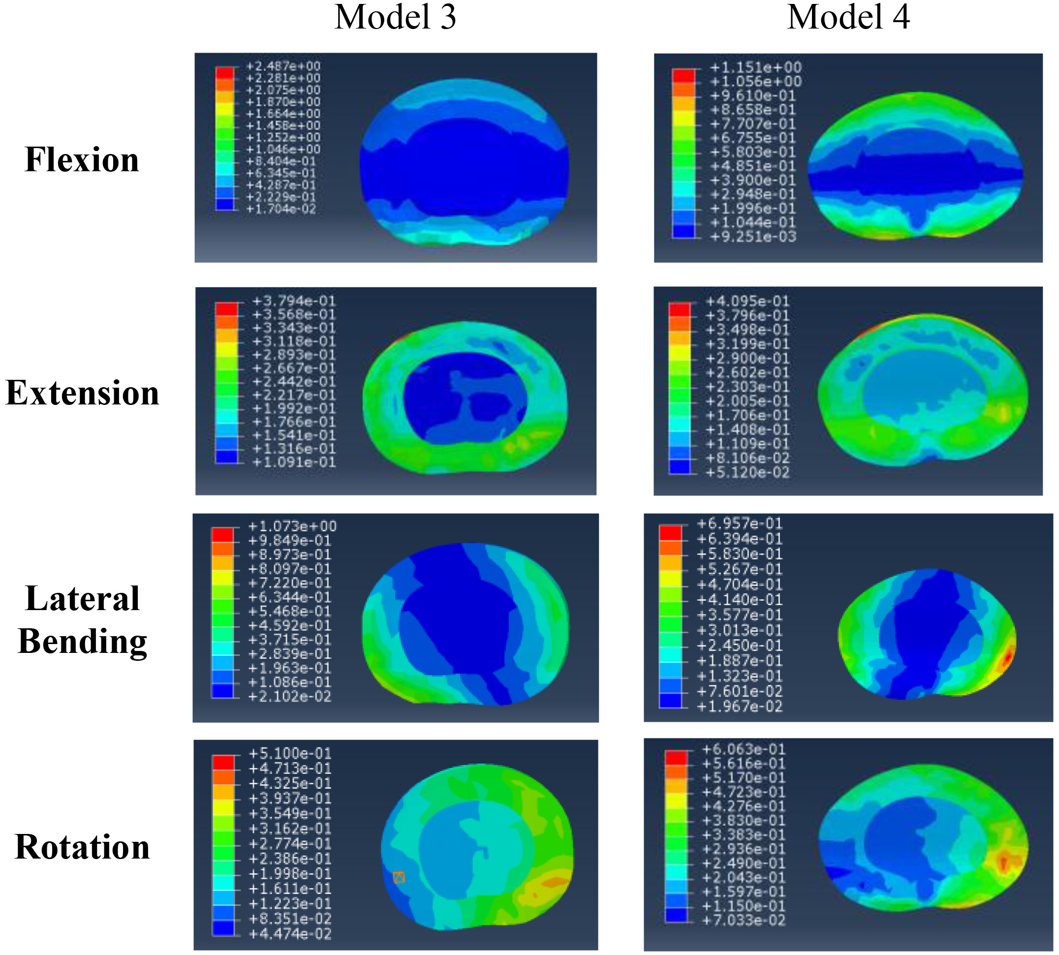
Figure 6.
Stress of hyperelastic FE models.
The stresses and displacements calculated by the four FE models under a variety of loading cases are shown by Tables 4–8. Much larger displacements of AF were produced by hyperelastic FE models (models 3 and 4) than that of elastic FE models (models 1 and 2). Displacement values of FE model 3 (healthy disc) were larger than FE model 4 (herniated disc) while under the loading conditions of flexion, extension, lateral bending, and compression. However, while under rotation, FE model 4 gave larger displacement than FE model 3. It is reasonable to assume that larger displacement results from larger stiffness under the same loading conditions. Other than FE model 4 under flexion, the stresses of annulus fibrosus were higher than those of nucleus pulposus. For the hyperelastic models, stresses of facet joint of herniated disk increased by 495% and 301% than healthy disc under extension and rotation, respectively.
Figure 5 shows the stress and displacement nephograms of the four FE models under axial load of 300 N, and Fig. 6 presents the stress nephograms of hyperelastic FE models under flexion, extension, left lateral bending, and rotation. Figure 5 shows that the posterior of annulus fibrosus under axial load had a high stress concentration. Annular fibrosus’ inner layer stress was less than outer layers and more than nucleus pulposus. Figures 5 and 6 both show that under all loading cases, posterolateral had the greatest amount of stress and displacement of annular fibrosus. Stress of nucleus pulposus was greatly reduced with the loss of water in the nucleus and changes of collagen fibers. As shown in Fig. 5, the distribution of the stress in the herniated disc was disturbed and there was a higher stress concentration. In comparison to a healthy disc, when more stress concentrations appear at annulus fibrosus, it is easier for damage to occur in the herniated disc, resulting in lumbar disc herniation.
4.Conclusions
FEM was used to investigate the mechanical behaviors of healthy and herniated IVD in this study. Hyperelastic constitutive model was adopted for the FE analysis of nonlinear hyperelastic response of annulus fibrosus instead of the elastic constitutive model. Four FE models were established to calculate the stiffness of the vertebral body and analyze the stress and displacement of IVD under the loading conditions of flexion, extension, lateral bending, and rotation. By comparing the stiffness calculated by FEM with the experimental data available in published literature, it can be found that hyperelastic FE models have much better capability to describe the mechanical behaviors of IVD than elastic FE models. FE analysis shows that annulus fibrosus of the herniated disc has a higher stress concentration than the healthy disc. Lumbar disc herniation results from the damage induced by higher stress concentration. Numerical examples of FE analysis indicate that the FEM with hyperelastic constitutive model is capable of analyzing the mechanical behaviors of IVD.
Conflict of interest
None to report.
Acknowledgments
This work is financially supported by the National Natural Science Foundation of China (11262002 and 81360552) and the Natural Science Foundation of Guangxi Province, China (2013GXNSFAA019142). Those supports are gratefully acknowledged.
References
[1] | Ferguson SJ, Steffen T. Biomechanics of the aging spine. European Spine Journal. (2003) ; 12: (Suppl. 2): S97-S103. |
[2] | Kelsey JL, White AA. Epidemiology and Impact of Low-Back Pain. Spine. (1980) ; 5: : 133-142. |
[3] | Belytschko T, Kulak RF, Schultz AB, Galante JO. Finite element stress analysis of an intervertebral disc. Journal of Biomechanics. (1974) ; 7: : 277-285. |
[4] | Goel VK, Monroe BT, Gilbertson LG, et al. Interlaminar shear stresses and laminae separation in a disc, Finite element analysis of the L3-L4 motion segment subjected to axial compressive loads. Spine. (1995) ; 20: (6): 689-698. |
[5] | Eberlein RA, Gerhard A, Holzapfel GA. An Anisotropic Model for Annulus Tissue and Enhanced Finite Element Analyses of Intact Lumbar Disc Bodies. Computer Methods in Biomechanics & Biomedical Engineering. (2001) ; 4: (3): 209-229. |
[6] | Peng XQ, Guo ZY, Moran B. An anisotropic hyperelastic constitutive model with fiber-matrix shear interaction for the human annulus fibrosus. Journal of Applied Mechanics. (2006) ; 73: : 815-824. |
[7] | Park WM, Kim YH, Lee S. Effect of intervertebral disc degeneration on biomechanical behaviors of a lumbar motion segment under physiological loading cases. Journal of Mechanical Science and Technology. (2013) ; 27: (2): 483-489. |
[8] | Schroeder Y, Wilson W, Huyghe JMRJ, Baaijens FPT. Osmoviscoelastic finite element model of the intervertebral disc. European Spine Journal. (2006) ; 15: (3): 361-371. |
[9] | Natarajan RN, Williams JR, Lavender SA, Andersson GBJ. Poro-elastic finite element model to predict the failure progression in a lumbar disc due to cyclic loading. Computers and Structures. (2007) ; 85: (11-14): 1142-1151. |
[10] | Schmidt H, Shirazi-Adl A, Galbusera F, Wilke HJ. Response analysis of the lumbar spine during regular daily activities – a finite element analysis. Journal of Biomechanics. (2010) ; 43: (10): 1849-1856. |
[11] | Rohlmann A, Zander T, Schmidt H, Wilke H, Bergmann G. Analysis of the influence of disc degeneration on the mechanical behaviour of a lumbar motion segment using the finite element method. Journal of Biomechanics. (2006) ; 39: (13): 2484-2490. |
[12] | Tang S, Rebholz BJ. Does anterior lumbar interbody fusion promote adjacent degeneration in degenerative disc disease? A finite element study. Journal of Orthopaedic Science. (2011) ; 16: (2): 221-228. |
[13] | Cegoñino J, Moramarco V, Calvo-Echenique A, Pappalettere C, Pérez del Palomar A. A Constitutive Model for the Annulus of Human Intervertebral Disc: Implications for Developing a Degeneration Model and Its Influence on Lumbar Spine Functioning. Journal of Applied Mathematics. Vol. (2014) , Article ID 658719, 15 pages. doi:10.1155/2014/658719. |
[14] | Antonius R, Anke M, Thomas Z, et al. Effect of an artificial disc on lumbar spine biomechanics: a probabilistic finite element study. European Spine Journal. (2008) ; 18: (1): 89-97. |
[15] | Zuo Z, You XC, Liao JH, et al. Finite Element Analysis and its Applications Based on ABAQUS. Tsinghua University Press, Beijing, (2009) . (in Chinese). |
[16] | Sharma M, Langrana NAJ, Rodriguez. Role of ligaments and facets in lumbar spinal stability. Spine. (1995) ; 20: (8): 887-900. |
[17] | Shirazi-Adl A, Parnianpour M. Role of posture in mechanics of the lumbar spine in compression. Journal of Spinal Disorders. (1996) ; 9: (4): 277-286. |
[18] | Goel VK, Kong W, Han JS, et al. A combined finite element and optimization investigation of lumbar spine mechanics with and without muscles. Spine. (1993) ; 18: (11): 1531-1541. |
[19] | Guan YB, Yoganandan N, Moore J, Pintar FA, Zhang JY, Maiman DJ, Laud P. Moment-rotation responses of the human lumbosacral spinal column. Journal of Biomechanics. (2007) ; 40: (9): 1975-1980. |
[20] | Panjabi MM, Oxland TR, Yamamoto I, et al. Mechanical behavior of the human lumbar and lumbosacral spine as shown by three-dimensional load-displacement curves. Journal of Bone and Joint Surgery American Volume. (1994) ; 76: (3): 413-24. |
[21] | Wilke HJ, Wenger K, Claes L. Testing criteria for spinal implants: recommendations for the standardization of in vitro stability testing of spinal implants. European Spine Journal. (1998) ; 7: (2): 148-154. |
[22] | Kanayama M, Ng JB, Abumi K, et al. Biomechanical analysis of anterior versus circumferential spinal reconstruction for various anatomic stages of tumor lesions. Spine. (1999) ; 24: (5): 445-450. |
[23] | Mimura M, Panjabi MM, Oxland RT, et al. Disc degeneration affects the multidirectional flexibility of the lumbar spine. Spine. (1976) ; 19: (12): 1371-1380. |
[24] | Schmidt H, Heuer F, Wilke HJ. Dependency of disc degeneration on shear and tensile strains between annular fiber layers for complex loads. Medical Engineering & Physics. (2009) ; 31: : 642-649. |


