
Numerical analysis of urine flow through the side holes of a double J stent in a ureteral stenosis
Abstract
Ureteral stenosis presents with a narrowing in the ureter, due to an intrinsic or extrinsic ureteral disease, such as ureter cancer or retroperitoneal fibrosis. The placement of a double J stent in the upper urinary system is one of the most common treatments of ureteral stenosis, along with the insertion of a percutaneous nephrostomy tube into the renal pelvis. The effect that the side holes in a double J stent have on urine flow has been evaluated in a few studies using straight ureter models. In this study, urine flow through a double J stent’s side holes was analyzed in curved ureter models, which were based on human anatomy. In ureteral stenosis, especially in severe ureteral stenosis, a stent with side holes had a positive effect on the luminal and total flow rates, compared with the rates for a stent without side holes. The more side holes a stent has, the greater the luminal and total flow rates. However, the angular positions of the side holes did not affect flow rate. In conclusion, the side holes in a double J stent had a positive effect on ureteral stenosis, and the effect became greater as the ureteral stenosis became more severe.
1.Introduction
Ureteral stenosis occurs when intrinsic ureteral lesions, caused by ureter cancer, or extrinsic ureteral lesions, caused by retroperitoneal fibrosis, disturb the urine flow in the upper urinary system. To relieve urine stagnation in the system, a ureteral stent is placed through nephrostomy or cystoscopy [1, 2, 3]. The most commonly used stent is the double J stent. Many medical equipment companies manufacture double J stents, which have geometric differences in their side holes. These differences could be linked to the differences in urine flow around the side holes.
A few studies have reported a numerical simulation of urine flow in a straight, stented ureter model [4, 5, 6, 7, 8], while other studies have analyzed urine flow in a curved, stented ureter model [9, 10]. The studies were performed for mild or no ureteral stenosis, and they demonstrated that the flow through the side holes either could not be visualized or was very small. However, the studies did not evaluate the flow through the side holes in a stented ureter model for various severities of ureteral stenosis. If the ureteral stenosis is mild to moderate, the extraluminal flow could be greater in the total flow in the stented ureter. However, if it is severe, the luminal (in-stent) flow could become important in maintaining efficient urine flow. The luminal flow could show various features, according to the severity of the ureteral stenosis. These features could differ from the luminal flow in cases where there is no ureteral stenosis or where there is an in-stent stenosis, which is formed through the side holes of the stent in the renal pelvis and proximal ureter and maintained in the mid-ureter and distal ureter [9, 10]. In this study, models of curved stented ureters with different severities of ureteral stenosis were created and analyzed numerically to evaluate the luminal and extraluminal flow rates, as well as the flow pattern around the stent’s side holes in the ureter.
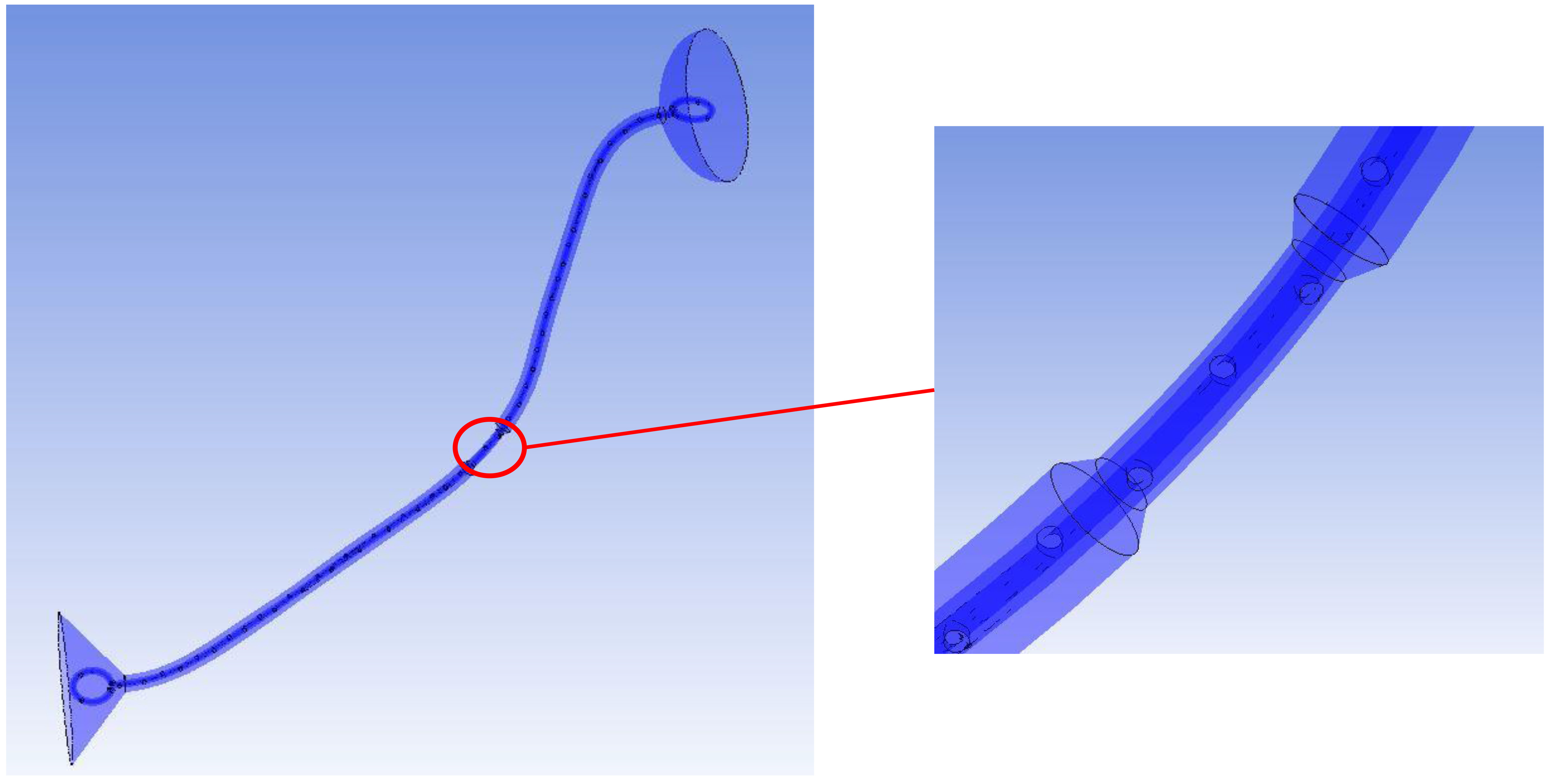
Figure 1.
A curved, stented, and stenosed ureter model. The stenosis is shown in the mid ureter.
2.Methods
2.1Modeling of a curved, stented, and stenosed ureter (Fig. 1)
Various curved, stented, and stenosed ureter models were made to represent ureters with different ureteral stenoses (33%, 52%, 74%, and 88%) and double J stents with different numbers of holes (11, 22, and 45) at different angular positions (45
It induced 33%, 52%, 74%, and 88% decreases in the ureteral area, which corresponded to 37%, 55%, 77%, and 92% decreases, considering the ureteral area was occupied by the stent.
The inner and outer diameters of the double J stent were 1 mm and 2 mm, respectively. The stent consisted of two coils at both ends and a shaft in the middle. The side holes and end holes in the coils were called ports to differentiate them from the side holes in the shaft. The side holes and ports in the stent were round and 1 mm wide. Each coil had five ports, including one end hole. The shaft had 0, 11, 22, or 45 side holes. Type 1 of the double J stent did not have any side holes. Table 1 shows the details of the ten types of double J stents. The combination of stenosed ureters and stents resulted in 40 models of curved, stented, and stenosed ureters. The axis of the stent shaft was the same as that of the ureter. Thus, they had the same curvature.
Table 1
Ten types of double J stents
| Type | Number of side holes | Angular positions of side holes | Interval of holes |
|---|---|---|---|
| 1 | 0 | – | – |
| 2 | 11 | 0 | 2 cm |
| 3 | 11 | 0 | 2 cm |
| 4 | 11 | 0 | 2 cm |
| 5 | 22 | 0 | 1 cm |
| 6 | 22 | 0 | 1 cm |
| 7 | 22 | 0 | 1 cm |
| 8 | 45 | 0 | 0.5 cm |
| 9 | 45 | 0 | 0.5 cm |
| 10 | 45 | 0 | 0.5 cm |
2.2Governing equations for fluid flow and numerical simulations
We applied the same governing equations for fluid flow and the same boundary conditions for numerical simulations as in our previous studies [9, 10]. We used Ansys CFX to investigate the flow phenomenon, and the CFX codes used a pressure-based algebraic multigrid (AMG) coupled solver. The continuity and momentum equations are shown in Eqs (1)–(2), where
(1)
(2)
Also, a urine viscosity and density of 0.654 mPa
3.Results and discussion
3.1Total flow rate and individual flow rates
As ureteral stenosis became severe, the total flow rate in the curved, stented, and stenosed ureter decreased: the total flow rate was about 43–44 ml/h in 33% ureteral stenosis, 33–34 ml/h in 52% ureteral stenosis, 13–17 ml/h in 74% ureteral stenosis, and 5–11 ml/h in 88% ureteral stenosis (Fig. 2).
Figure 2.
Total flow rates in a curved, stented, and stenosed ureter for (a) 33%, (b) 52%, (c) 74%, and (d) 88% ureteral stenoses.
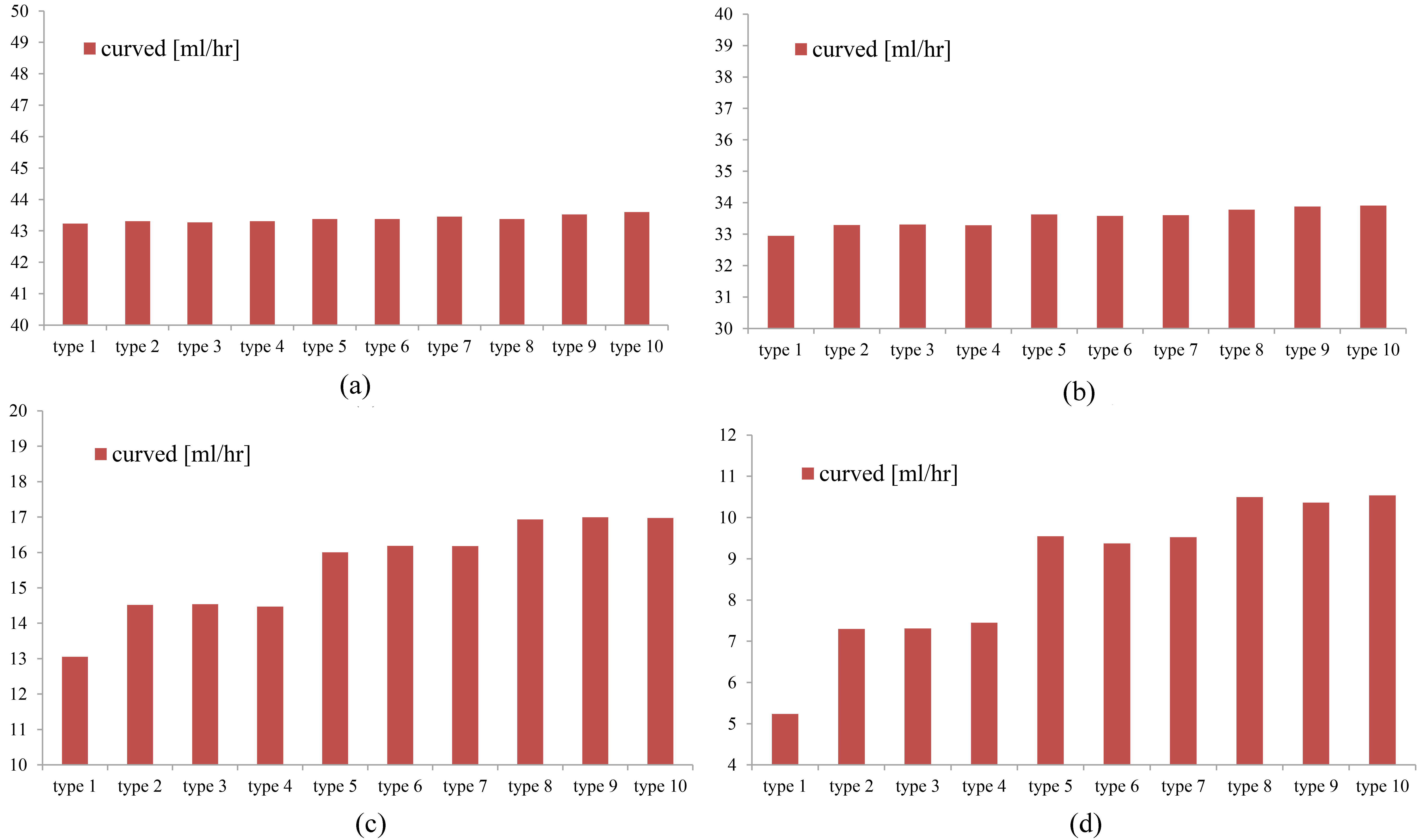
In the models with mild to moderate ureteral stenosis (33% and 52%), the total flow rate with a type 1 stent, which has no side holes, was similar to the flow rate with other types. In contrast, in the models with severe ureteral stenosis (74% and 88%), the total flow rate with a type 1 stent was less than the flow rate with other types. This shows the minor role the side holes play in the total flow rate in mild to moderate ureteral stenosis and the relatively major role the side holes play in the total flow rate in severe ureteral stenosis. This is confirmed in Fig. 2.
The number of a stent shaft’s side holes affected the total flow rate. The greater the number of side holes, the greater the total flow rate (Fig. 2). This tendency was shown to be greater in severe ureteral stenosis (74% and 88%), which means that the side holes have a greater effect as ureteral stenosis becomes more severe. The geometry and the different angular positions (45
Figure 3.
Flow rates in the proximal or distal ureter (a) away from the stenosis and (b) at the stenosis in the mid ureter in curved, stented, and stenosed ureter models (type 9 stent; side holes at 0.5 cm intervals, 90
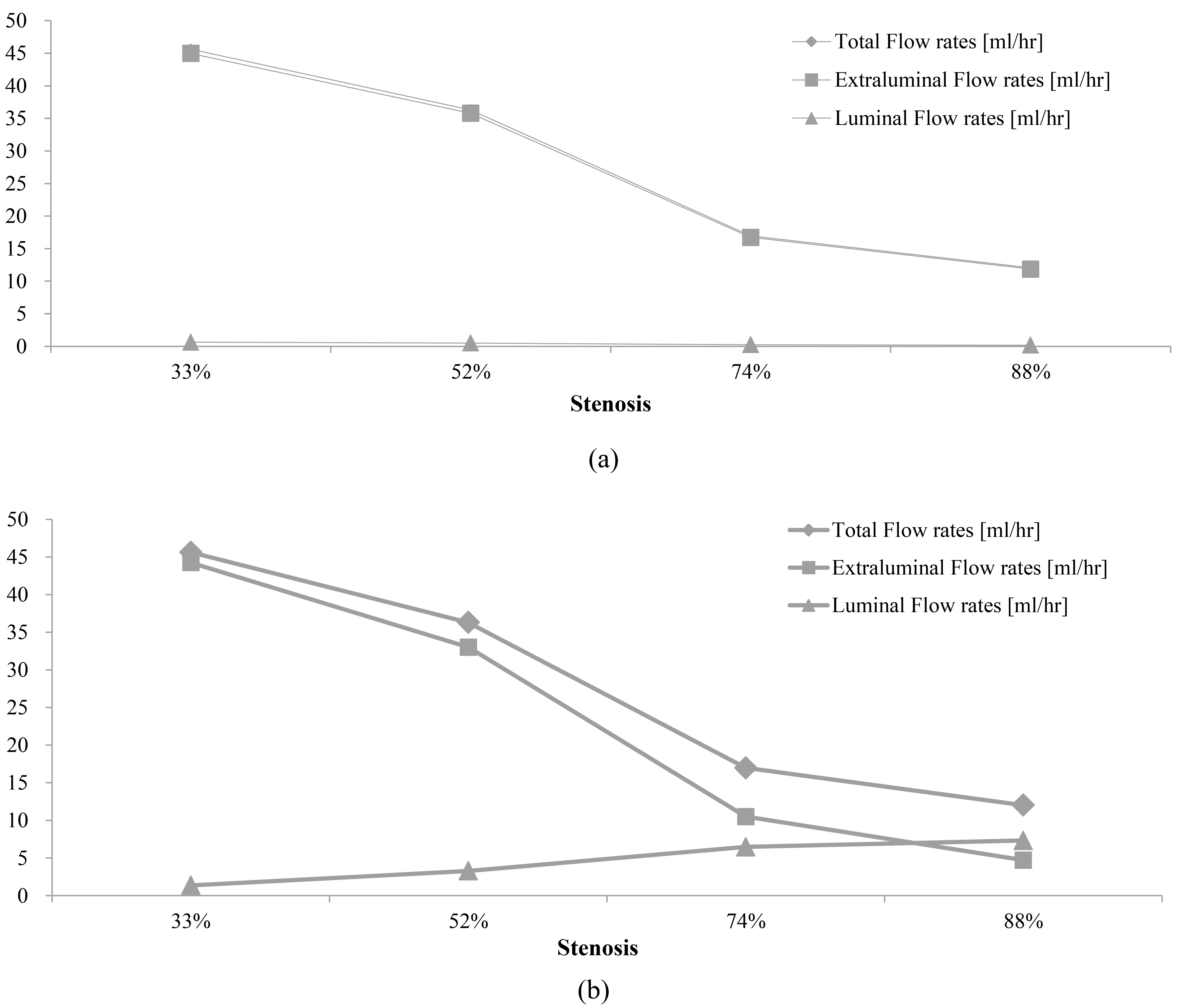
The luminal flow rate in the proximal or distal ureter located far from the stenosis was small, while the luminal flow rate at the stenosis was relatively large. This is demonstrated in Figs 3 and 4. The luminal flow rates with a type 9 stent, located far from the stenosis, were 0.6 ml/h at 33% ureteral stenosis, 0.4 ml/h at 52% ureteral stenosis, 0.2 ml/h at 74% ureteral stenosis, and 0.15 ml/h at 88% ureteral stenosis. The luminal flow rates with a type 9 stent located at the stenosis were 1.4 ml/h at 33% ureteral stenosis, 3.4 ml/h at 52% ureteral stenosis, 6 ml/h at 74% ureteral stenosis, and 7 ml/h at 88% ureteral stenosis. The ratio of luminal flow rate to total flow rate was 1.2
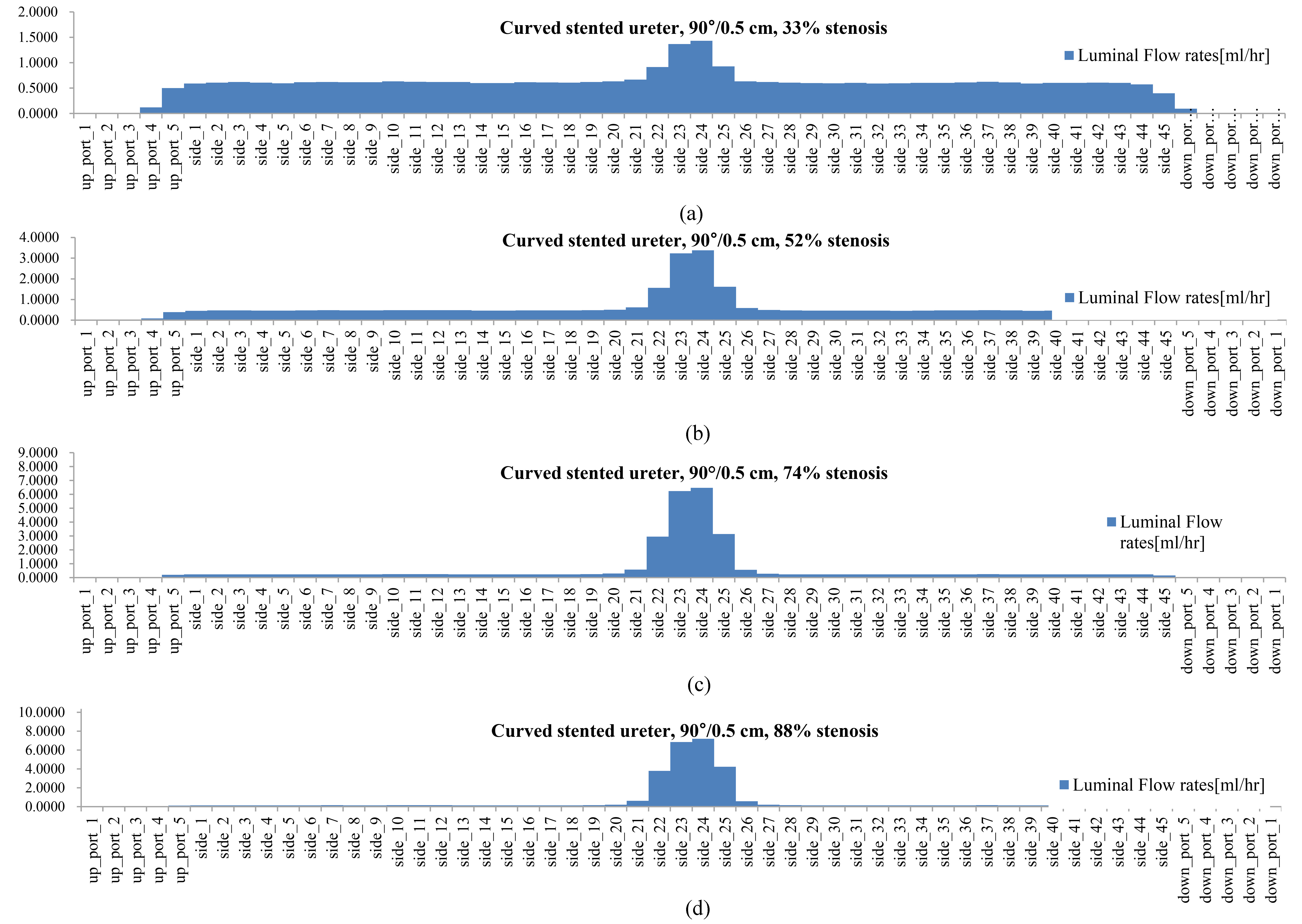
Figure 4.
The luminal flow rate in the curved, stented, and stenosed ureters with (a) 33% ureteral stenosis, (b) 52% ureteral stenosis, (c) 74% ureteral stenosis, and (d) 88% ureteral stenosis (type 9 stent; side holes at 0.5 cm intervals, 90
In our previous study [10], there was no difference in the luminal flow rates in stented ureters with diameters of 3 mm and 4.57 mm without any focal ureteral stenosis. A 3 mm-sized ureter could have a diffuse ureteral narrowing of 4.57 mm, which is different from a focal ureteral narrowing. This diffuse narrowing did not affect the luminal flow rate, although it did affect the extraluminal flow rate and the total flow rate. The role of the side holes in the stent shaft, in the case of diffuse ureteral narrowing, was limited. In contrast, the role of the side holes in the stent shaft, in the case of a focal ureteral narrowing, was prominent in this study.
Figures 3 and 4 demonstrate that the luminal flow rate in the proximal or distal ureter that was located far from a mild ureteral stenosis was greater than the luminal flow rate that was far from a severe ureteral stenosis. In contrast, the luminal flow rate at a severe ureteral stenosis was greater than the luminal flow rate at a mild ureteral stenosis. This means that, for mild ureteral stenosis, the side holes of a double J stent played a role along the ureter, which included both far from the stenosis and at the stenosis. For severe ureteral stenosis, the side holes mainly played a role in the mid ureter, in which there is a stenosis.
Figure 5.
Luminal flow rates at the proximal fifth port, side holes, and distal fifth port in curved, stented, and stenosed ureters with a 74% stenosis.
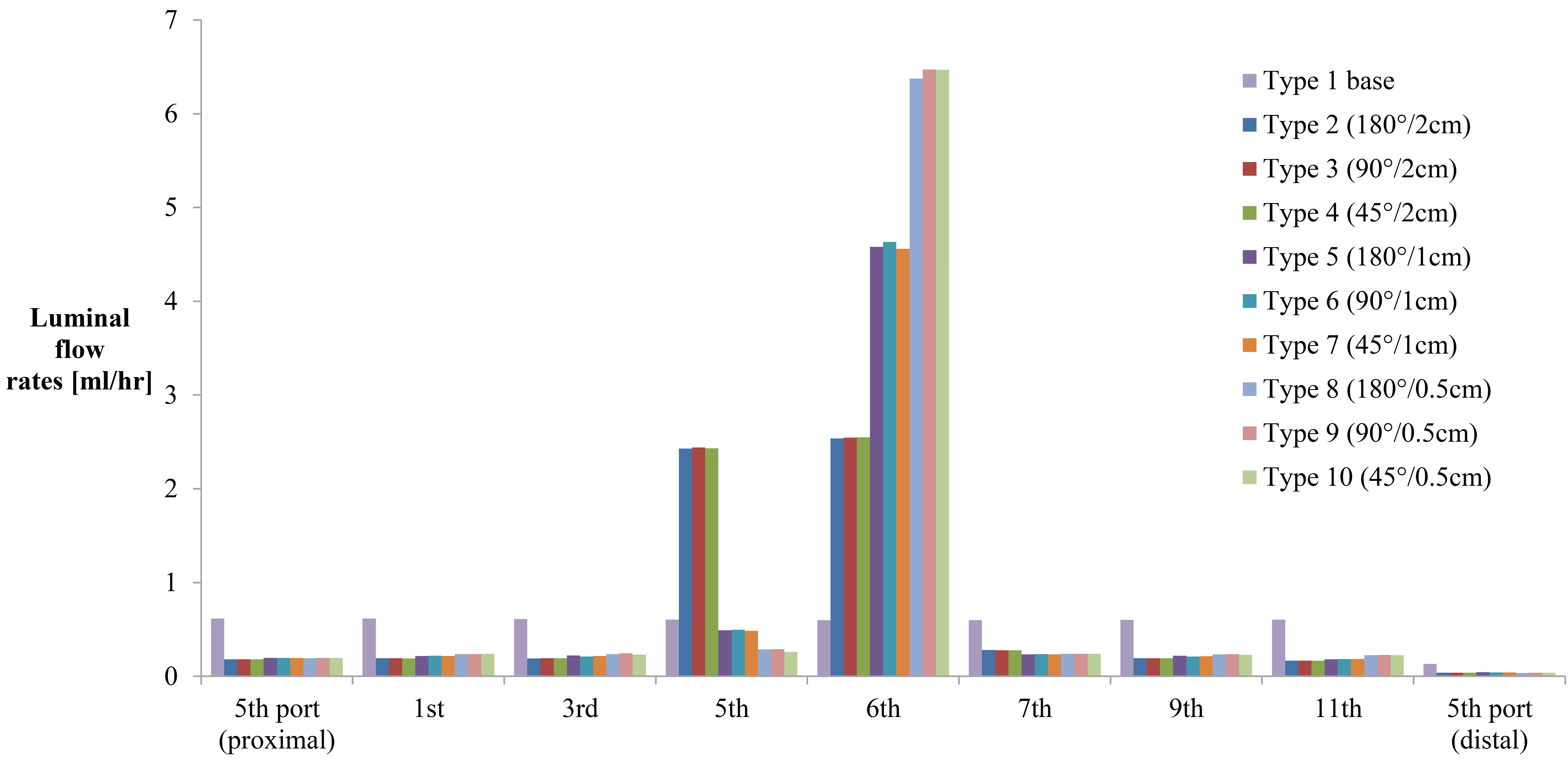
Figure 5 shows a high luminal flow rate at the stenosis and a relatively low luminal flow rate far from the stenosis. It also shows a higher luminal flow rate at the ureter, just proximal to the stenosis, with type 2, 3, and 4 stents (side holes at 2 cm intervals), compared with type 5 to 10 stents (side holes at 1 cm or 0.5 cm intervals). This is because the fifth side hole is the last side hole before the stenosis in type 2, 3, and 4 stents and the last chance for inflow to the stent. The luminal flow rate at the segment just proximal to the stenosis was similar to the rate at the stenosis. Actually, the luminal flow rate at the last side hole before the stenosis in type 5 to 10 stents (the 11th or 22nd side hole) was similar to the flow at the stenosis (the 12th side hole or the 23rd–25th side holes). This is confirmed in Fig. 6, which shows the changes in the luminal flow rate before, at, and after the stenosis in curved, stented, and stenosed ureter models with type 1, 3, 6, and 9 stents and a 74% ureteral stenosis.
Figure 6.
Flow rate patterns along the stent in curved, stented, and stenosed ureters with a 74% stenosis for (a) type 1 stent with no side holes, (b) type 3 stent with side holes at 0.5 cm intervals, 90
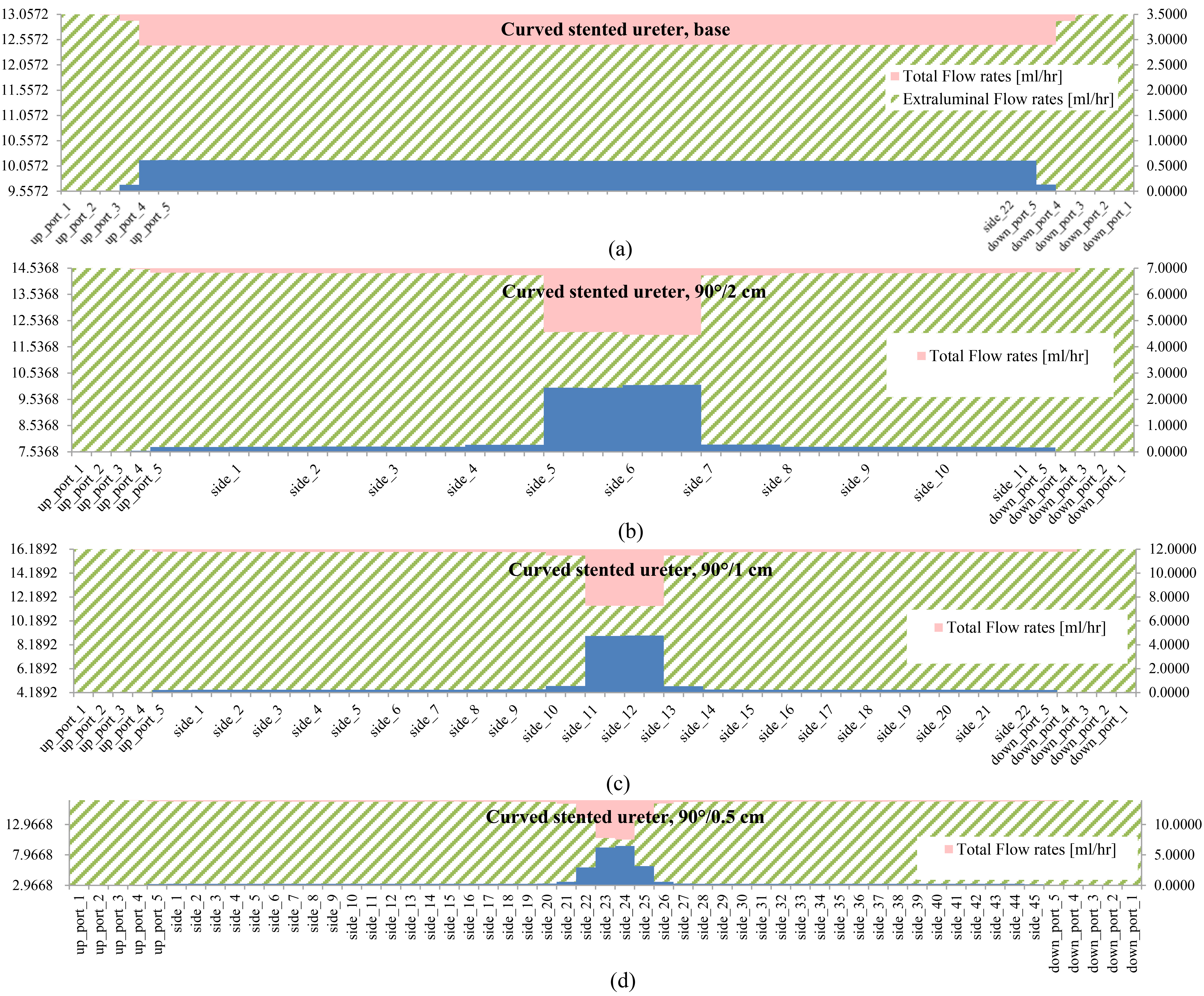
Figures 5 and 6 show that the number of side holes affected the luminal flow rate for a severe ureteral stenosis (74%). The greater the number of side holes in a stent shaft, the greater the luminal flow rate. The effect of the side holes became greater near and around the stenosis. The geometry and different angular positions (45
From these results, it could be stated that a double J stent with many side holes and a large diameter is more helpful in treating the condition of severe ureteral stenosis, because it increases the luminal flow rate and, in turn, increases the total flow rate. In contrast, a double J stent with few side holes and a small diameter is more helpful in treating the condition of mild ureteral stenosis, because the number of side holes does not affect the luminal flow rate, and a stent with a small diameter does not affect the extraluminal flow rate.
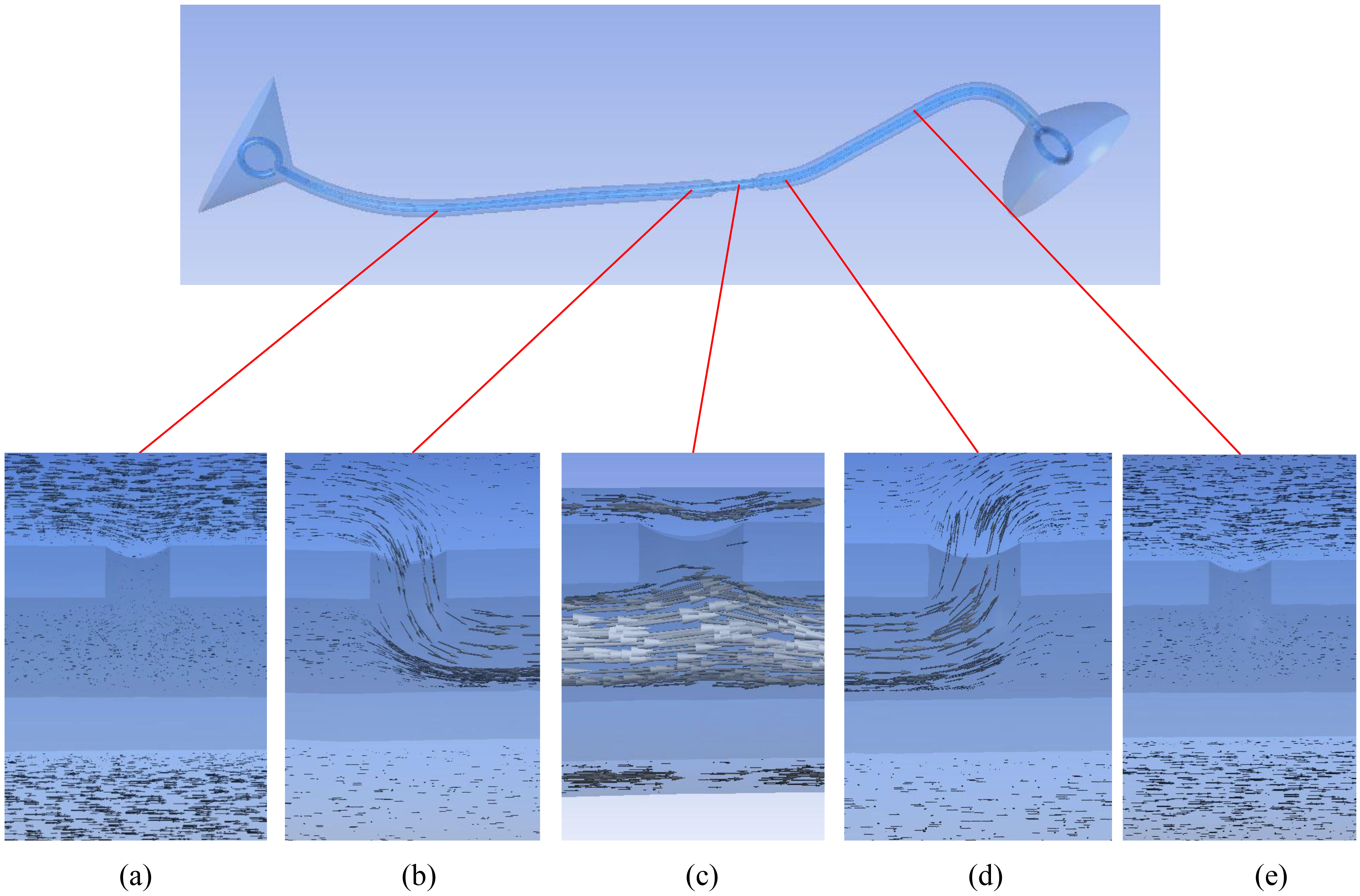
Figure 7.
Flow patterns around the side holes of a double J stent in a curved, stented, and stenosed ureter with a 74% stenosis (type 9 stent; side holes at 0.5 cm intervals, 90
3.2Flow pattern around side holes of a stent shaft
Figure 7 shows the flow vectors around the side holes at locations just before, just after, and at the stenosis, as well as around the side holes in the proximal and distal ureter. There was no communication between the luminal and extraluminal spaces through the side holes in the proximal and distal ureter. Inflow into the stent through a side hole was detected just before the stenosis, and the outflow from the stent through a side hole was detected just after the stenosis. At the stenosis, the luminal flow tried to leave the stent through a side hole, but the flow was impeded by the extraluminal flow.
Figure 8.
In-stent pressure in a curved, stented, and stenosed ureter with a 74% stenosis (type 9 stent; side holes at 0.5 cm intervals, 90
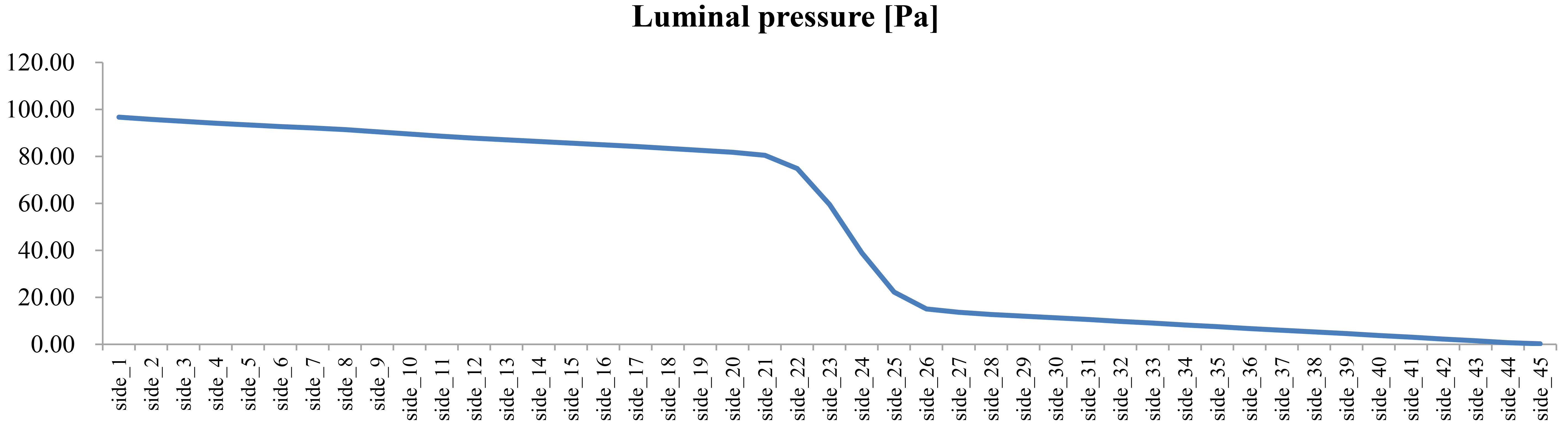
Figure 8 shows the changes in the pressure in the stent. A slow decrease in the pressure was detected along the ureter, except for an abrupt decrease in pressure at the stenosis. Since the luminal space is connected to the extraluminal space, there was a similar pressure along the ureter, although there could have been minor pressure differences at some points. The abrupt pressure drop resulted from the ureteral stenosis.
The ureter does not have a constant diameter; rather, it tapers toward the distal end. In addition, the ureter is not rigid. However, for the purposes of this study, we assumed that the ureter had a constant diameter and that it was rigid. This assumption is a limitation in evaluating urine flow rate and pattern in the curved and stented ureter. In the future, it is necessary to consider using undulated and tapered ureters and elastic ureteral walls.
4.Conclusions
In this study, the necessity of side holes in a double J stent was demonstrated, especially in the treatment of severe ureteral stenosis. In mild ureteral stenosis, there was no difference in the total flow rate between a stent without side holes and a stent with side holes. In contrast, for severe ureteral stenosis, a stent with many side holes had a positive effect on the total flow rate.
To treat ureteral stenosis, the greater the number of side holes a stent has, the greater the luminal flow rate, which is linked to a greater total flow rate. The number of side holes around the stenosis is more important than having holes along the whole ureter. It would be ideal to make a double J stent that has more side holes at the level of the ureteral stenosis. However, double J stents are mass produced, and it is not possible to customize a double J stent for each patient. In the future, customized double J stents based on a CFD analysis might be available to treat patients.
In contrast to the number of side holes, we found that the geometry and location of the side holes did not affect the luminal and total flow rates.
To treat ureteral stenosis, a double J stent is inserted to relieve the urine flow disturbance in the upper urinary tract. It should be kept in mind that the stent itself decreases the total flow rate [11, 12, 13, 14, 15]. Therefore, the costs of treating mild ureteral stenosis with a stent might be greater than the benefits, because of the decrease in total flow rate that occurs from the stent insertion. However, in severe ureteral stenosis, a decrease in the total flow rate due to a stent insertion might be compensated with a ureter expansion at the stenosis and an increase in flow rates through the artificially achieved luminal and extraluminal spaces.
In conclusion, the side holes in a double J stent play an important role in treating ureteral stenosis, and the holes become more important as the severity of the ureteral stenosis increases.
Conflict of interest
None to report.
Acknowledgments
This research was supported by the Basic Science Research Program through the National Research Foundation of Korea (NRF), funded by the Ministry of Science, ICT & Future Planning (2014R1A1A1003987).
References
[1] | Chung HH, Kim KD, Won JY, Won JH, Cho SB, Seo TS, Park SW, Kang BC. Multicenter experience of the newly designed covered metallic ureteral stent for malignant ureteral occlusion: Comparison with double J stent insertion, Cardiovascular Interventional Radiology, 37: ((2014) ), 463–470. |
[2] | Al-Aown A, Kyriazis I, Kallidonis P, Kraniotis P, Rigopoulos C, Karnabatidis D, Petsas T, Liatsikos E. Ureteral stents: New ideas, new designs, Therapeutic Advances in Urology, 2: ((2010) ), 85–92. |
[3] | Venkatesan N, Shroff S, Jayachandran K, Doble M. Polymers as ureteral stents, Journal of Endourology, 24: ((2010) ), 191–198. |
[4] | Tong JC, Sparrow EM, Abraham JP. Numerical simulation of the urine flow in a stented ureter, Journal of Biomechanical Engineering, 129: ((2007) ), 187–192. |
[5] | Siggers JH, Waters S, Wattis J, Cummings L. Flow dynamics in a stented ureter, Mathematical Medicine and Biology, 26: ((2009) ), 1–24. |
[6] | Cummings LJ, Waters SL, Wattis JA, Graham SJ. The effect of ureteric stents on urine flow: Reflux, Journal of Mathematical Biology, 49: ((2004) ), 56–82. |
[7] | Clavica F, Zhao X, El Mahdy M, Drake MJ, Zhang X, Carugo D. Investigating the flow dynamics in the obstructed and stented ureter by means of a biomimetic artificial model, PLoS ONE, 9: ((2014) ), e87433. |
[8] | Carugo D, Zhang X, Drake JM, Clavica F. Formation and characteristics of laminar vortices in microscale environments within an obstructed and stented ureter: A computational study, 18th International Conference on Miniaturized Systems for Chemistry and Life Sciences, MicroTAS, San Antonio, USA, (2014) , 1056–1058. |
[9] | Kim H, Choi YH, Lee SB, Baba Y, Kim K, Suh S. Numerical analysis of the urine flow in a stented ureter with no peristalsis, Bio-medical Materials and Engineering, 26: ((2015) ), S215–S223. |
[10] | Kim K, Choi YH, Lee SB, Baba Y, Kim H, Suh S. Numerical analysis of the effect of side holes of a double J stent on flow rate and pattern, Bio-medical Materials and Engineering, 26: ((2015) ), S319–S327. |
[11] | Ramsay JW, Payne SR, Gosling PT, Whitfield HN, Wickham JE, Levison DA, The effects of double J stenting on unobstructed ureters: An experimental and clinical study, British Journal of Urology, 57: ((1985) ), 630–634. |
[12] | Kinn AC, Lykkeskov-Andersen H. Impact on ureteral peristalsis in a stented ureter: An experimental study in the pig, Urological Research, 30: ((2002) ), 213–218. |
[13] | Patel U, Kellett MJ. Ureteric drainage and peristalsis after stenting studied using colour doppler ultrasound, British Journal of Urology, 77: ((1996) ), 530–535. |
[14] | Ramsay JW, Whitfield HN. Bilateral pelviureteric junction obstruction: The case for endoscopic management, Journal of the Royal Society of Medicine, 78: ((1985) ), 590–593. |
[15] | Brewer AV, Elbahnasy AM, Bercowsky E, Maxwell KL, Shalhav KL, Kahn SA, McDougall EM, Clayman RV. Mechanism of ureteral stent flow: A comparative in vivo study, Journal of Endourology, 13: ((1999) ), 269–271. |


