
Design of a wearable cable-driven upper limb exoskeleton based on epicyclic gear trains structure
Abstract
BACKGROUND:
Many countries, including Japan, Italy, and China are experiencing demographic shifts as their populations age. Some basic activities of daily living (ADLs) are difficult for elderly people to complete independently due to declines in motor function.
OBJECTIVE:
In this paper, a 6-DOF wearable cable-driven upper limb exoskeleton (CABexo) based on epicyclic gear trains structure is proposed.
METHODS:
The main structure of the exoskeleton system is composed of three epicyclic gear train sections. This new exoskeleton has a parallel mechanical structure to the traditional serial structure, but is stiffer and has a stronger carrying capacity. The traditional gear transmission structure is replaced with a cable transmission system, which is quieter, and has higher accuracy and smoother transmission.
RESULTS AND CONCLUSIONS:
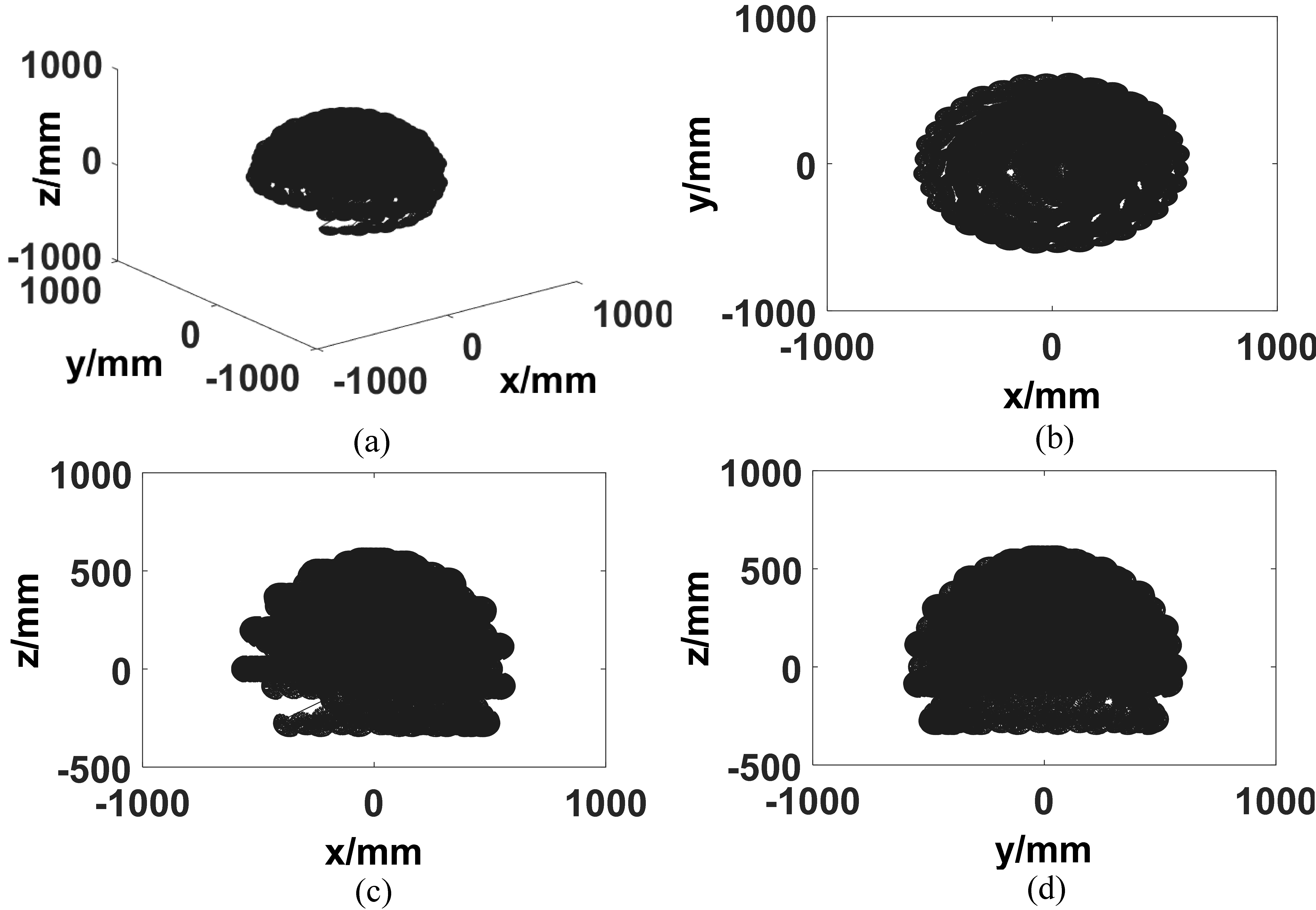
The static workspace of the exoskeleton is large enough to meet the demand of assisting aged and disabled individuals in completing most of their activities of daily living (ADLs).
1.Introduction
Many countries, including Japan, Italy, and China are experiencing demographic shifts as their populations age [1]. Some basic activities of daily living (ADLs) are difficult for elderly people to complete independently due to declines in motor function. Researchers are developing wearable exoskeleton robots to help the aged and disabled with completing ADLs [2, 3, 4, 5, 6, 7, 8, 9]. Ideally, wearable exoskeleton should be ergonomical, light-weight, highly reliable and accurate, very stiff, and inexpensive [2].
Many researchers have been investigating and developing a variety of types of wearable exoskeletons. Sugar et al. [2] developed a wearable exoskeleton robot named RUPERT to assist with the rehabilitation of arm functions, after a loss of function. RUPERT is actuated by pneumatic muscles through a serial link mechanism. Martinez et al. [3] designed a five degree of freedoms (DOF) upper limb exoskeleton actuated by DC motors and pneumatic muscles; its actuators were placed on an external base to decrease the mass and inertia of the exoskeleton by transmitting power via cables. Although the pneumatic muscle can provide flexible driving torques, these wearable exoskeleton systems actuated by pneumatic muscles with air cylinder may be difficult for patients to carry. Serea et al. [4] developed a hybrid FES-Electric upper arm wearable exoskeleton. However, FES creates muscle fatigue problems that have not yet been solved [5]. Most of these exoskeletons have a serial structure, which is easy to control and has a large workspace. However, each DOF of the serial link mechanism is driven by a single link, which makes the serial mechanism less stiff when compared with the parallel mechanism. This results in the carrying capacity of serial mechanism being weaker than in the parallel mechanism.
The cable-driven mechanism allows the system to be quieter and have high accuracy and smooth transmissions which are necessary for wearable exoskeletons [6, 7, 8, 9]. Mao et al. [6, 7] developed a cable driven arm exoskeleton (CAREX) for upper arm rehabilitation and Shao et al. [8] designed a 3-DOF cable-driven upper arm exoskeleton. However, the cable-driven parallel mechanism with flexible links is hard to be controlled. Ball et al. [9], proposed a traditional serial structure 5-DOF rehabilitation robot with the driving energy transmitted by cables. It can be controlled easily, however, it still exhibits the shortcomings of serial mechanism.
To overcome these problems, a cable-driven upper limb wearable exoskeleton based on epicyclic gear trains is proposed in this paper. This new structure has 6 DOFs, a three epicyclic gear train, and sections that compose the exoskeleton system. The revolution motion and the spinning motion of the planet wheel forms a 2-DOF coupled motion produced by the driving wheel and the driving link. The upper arm, forearm, and palm of the user’s upper limb are driven by corresponding planet wheels, and each planet wheel is supported and driven by two parts, which is similar to the parallel mechanism. The traditional gear transmission structure is replaced with a cable transmission system. The principle of the cable transmission system is the same as the gear transmission structure. However, it does not transmit torque using the meshing force between gears, rather, it uses cables on wheel faces which results in a quiet process, higher accuracy, and smoother transmission. The main body of the exoskeleton is rigid which can be controlled more easily than the parallel mechanism with flexible links. Further, we design a pre-tensioner to ensure the reliability of cable-driven mechanisms.
2.Mechanical design
2.1DOF selection and Denavit-Hartenberg parameters
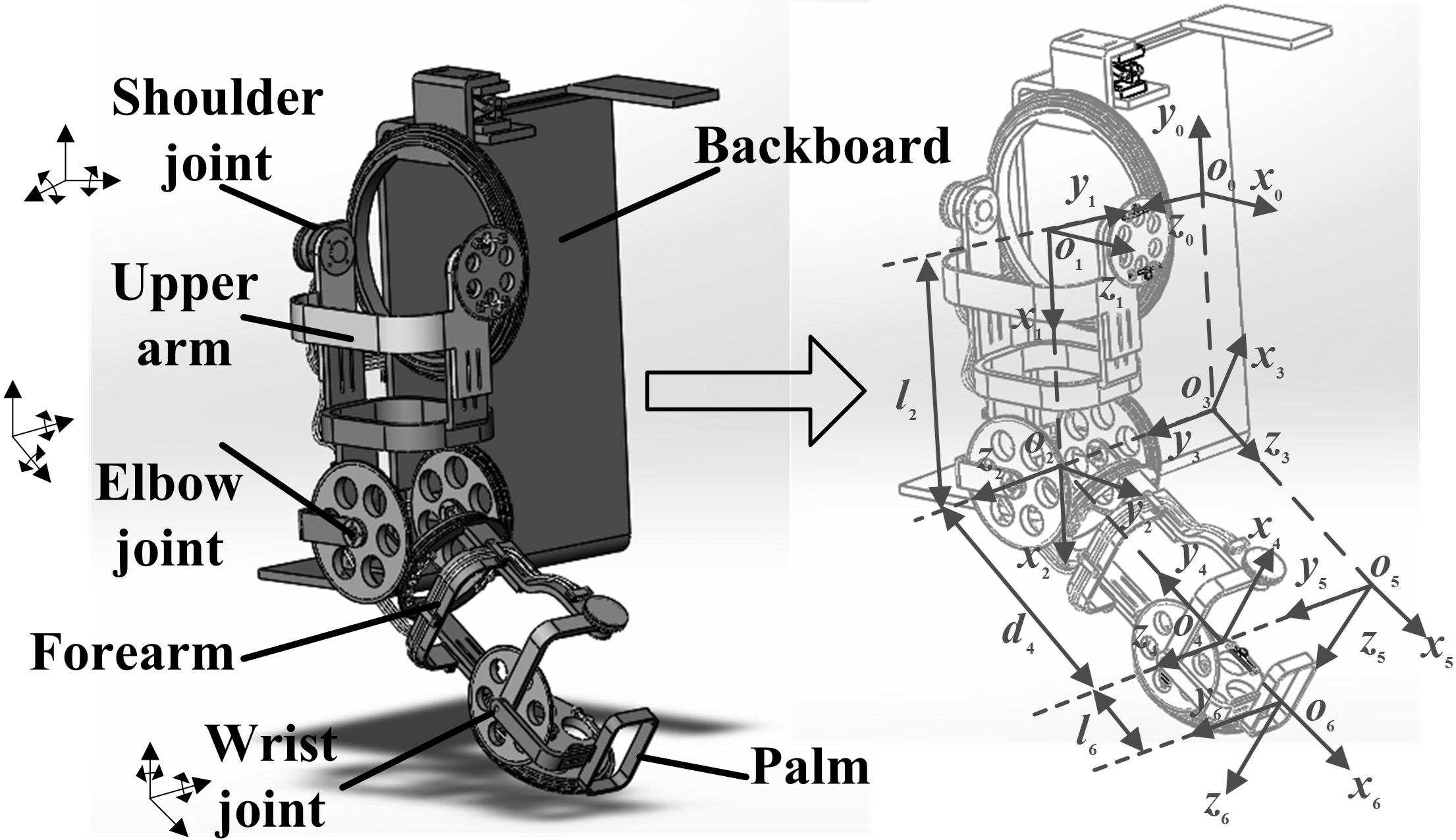
The shoulder internal/external rotation DOF is used less frequently than other DOFs [2]. The exosystem is composed of three epicyclic gear trains sections, ignoring the shoulder internal/external rotation DOF. As it has a large workspace, the exoskeleton could assist those with physical disabilities with most of the movements associated with ADLs as illustrated in Fig. 7 in section three. The model of the exoskeleton is shown in Fig. 1. All DC motors are placed on the backboard with an additional forces transmission system adapted from [3].
The Denavit-Hartenberg parameters of the exoskeleton listed in Table 1 can be obtained using the connecting rod coordinates established in Fig. 1. The range of the variable is based on Table 1. Here,
Table 1
The Denavit-Hartenberg parameters of the exoskeleton
| Link | Variable |
|
|
| Range of variable | |
|---|---|---|---|---|---|---|
| 1 |
| 0 | 0 | | ||
| 2 |
| 90 |
| 0 | ||
| 3 |
| 90 | 0 | 0 | 90 | |
| 4 |
| 0 |
| |||
| 5 |
| 90 | 0 | 0 | ||
| 6 |
| 0 |
| 0 | ||
Table 2
Comparison between CABexo and existing exoskeleton systems
| Exoskeleton systems | DOF | Driving type | Configuration | Motor arrangement |
|---|---|---|---|---|
| CABexo | 6 | DC motor(cable) | Similar parallel | Backboard |
| ARMin [13] | 6 | DC motor | Series | Corresponding joint |
| RUPERT III [2] | 5 | Pneumatic muscle | Series | Corresponding joint |
| CAREX [9] | 7 | DC motor(cable) | Parallel | Backboard |
| IKO [3] | 5 | DC motor | Series | Backboard |
Figure 1.
The 6-DOF upper limb exoskeleton model.
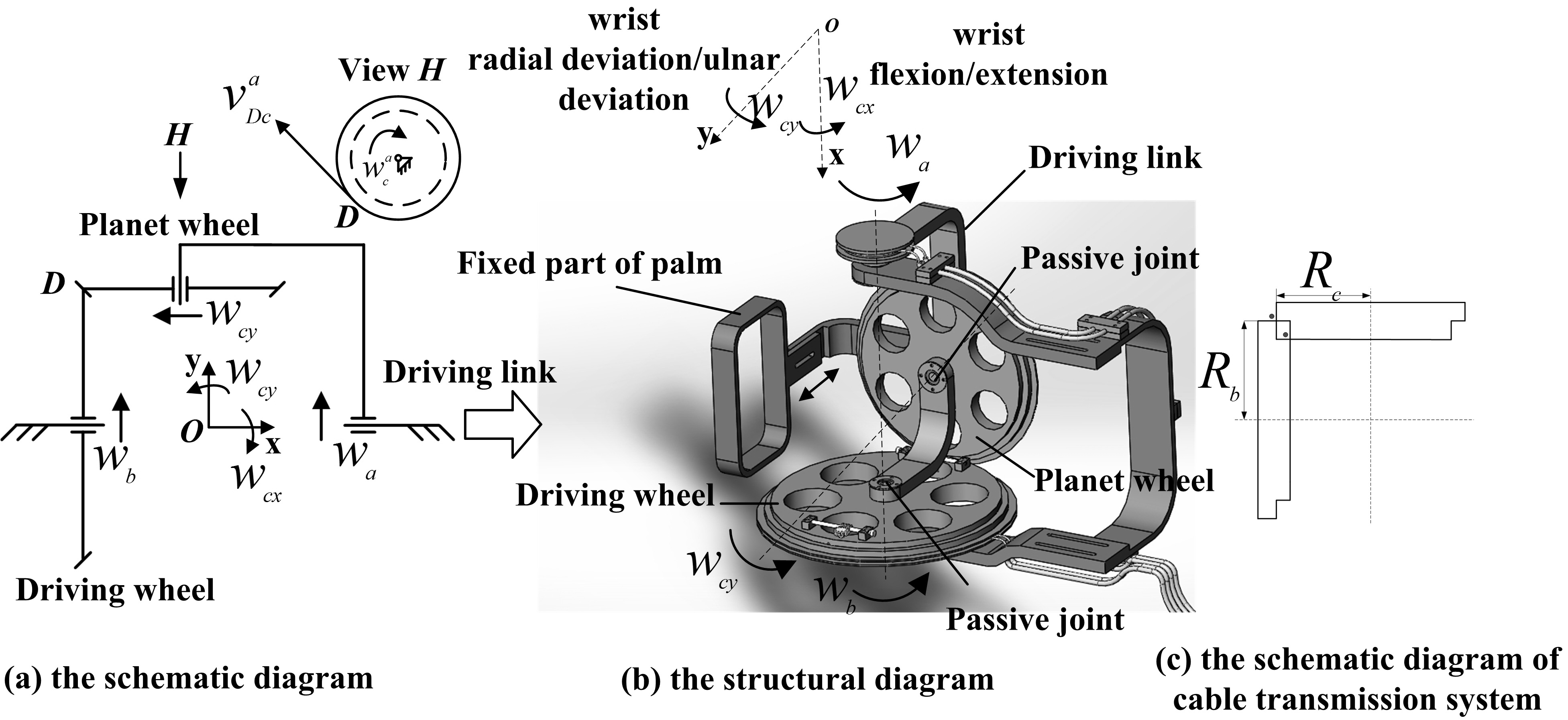
2.2The shoulder joint and the wrist joint parts of the exoskeleton
The shoulder joint part of the exoskeleton driving upper arm rotates with the shoulder joint and has two DOFs – the shoulder flexion/extension DOF and the shoulder abduction/adduction DOF. The schematic diagram of this part is shown in Fig. 2a and the structural diagram is illustrated in Fig. 2b. The radiuses of the driving wheel
(1)
Figure 2.
The shoulder joint part of exoskeleton.

To obtain
(2)
(3)
If the direction
The traditional gear transmission structure is replaced with cable transmission system as shown in Fig. 2c. As the cable is a flexible one-way transmission body, each DOF of the cable-driven mechanism can be accomplished by two cables placed on a wheel with a phase difference of 180 degrees. The driving wheel and the planet wheel should be two-stage as shown in Fig. 2c.
As it is hard to process large rolling bearings, we adopt a similar structure as shown in the sectioned view of the part in Fig. 2b. Steel balls with the same diameter, are placed in path one and path two; the steel balls function as simplified rolling bearings. The driving wheel and the driving link are each divided into two parts making it convenient to place the steel balls.
The wrist joint part of the exoskeleton is similar to the shoulder part. It has two DOFs – the wrist flexion/extension DOF and the wrist radial deviation/ulnar deviation DOF. A detailed diagram of the wrist joint part of exoskeleton is shown in Fig. 3. The angular speeds of the revolution and rotation of the planet wheel can be obtained by Eq. (3).
Figure 3.
The wrist joint part of the exoskeleton.
2.3The elbow joint part of the exoskeleton
The elbow joint part of the exoskeleton has two DOFs: the elbow flexion/extension and the forearm supination/pronation. The schematic diagram of the elbow joint part of exoskeleton is shown in Fig. 4. The motion of the planet wheel driving the forearm of the user to rotate with the elbow joint is controlled by two driving wheels. The radiuses of the driving wheel
(4)
(5)
Figure 4.
The elbow joint part of the exoskeleton.
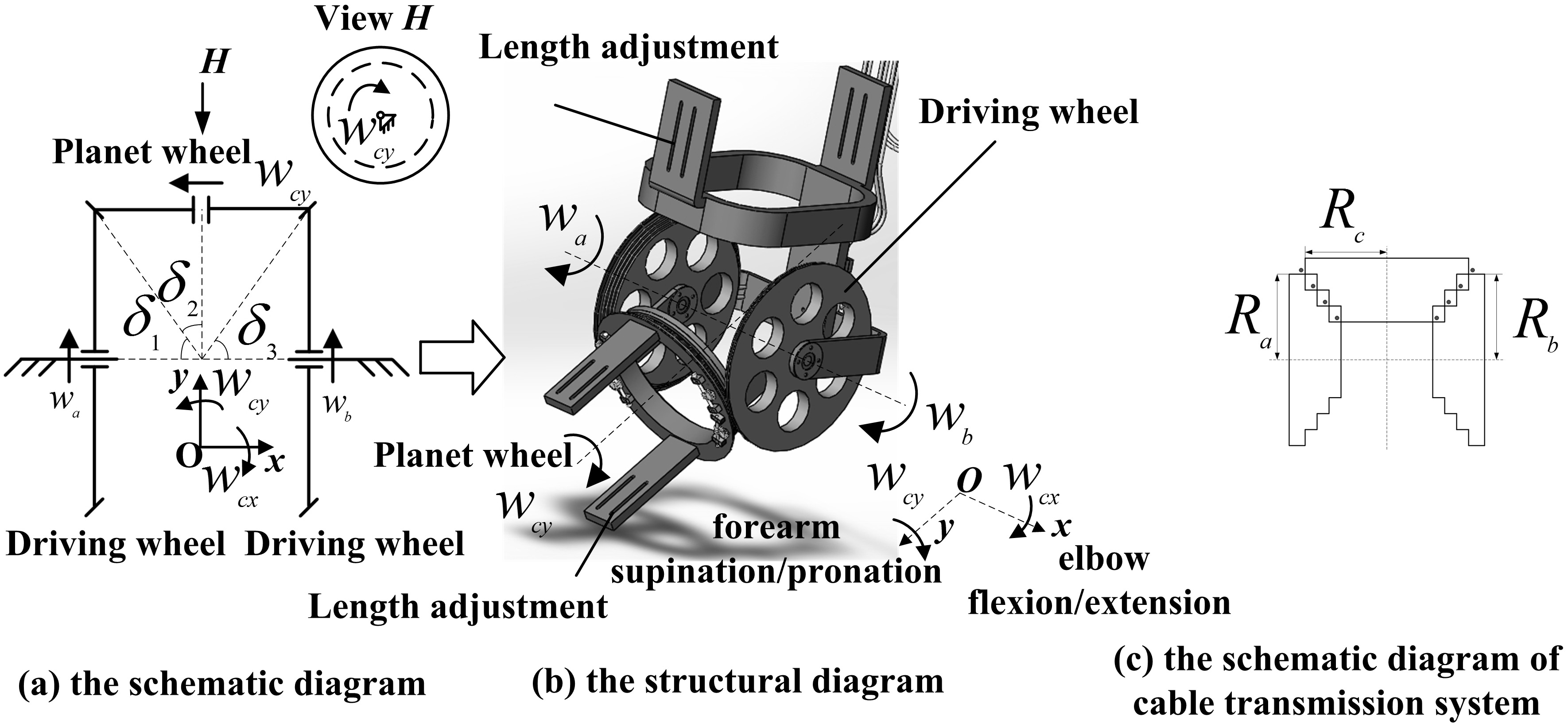
Figure 5.
The projection of the angular velocities.
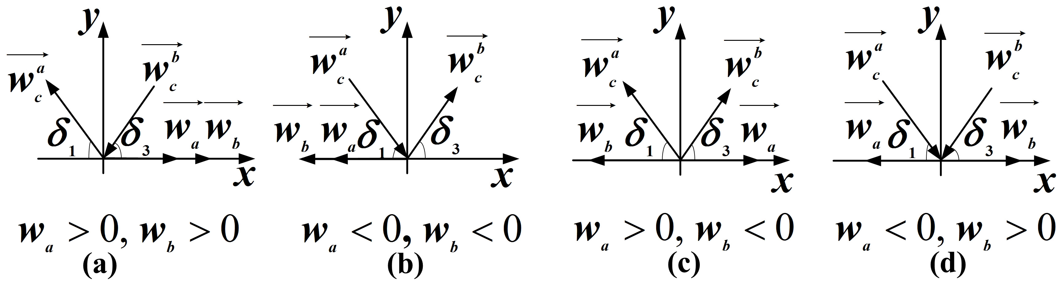
Figure 6.
The arrangement of pre-tensioner.
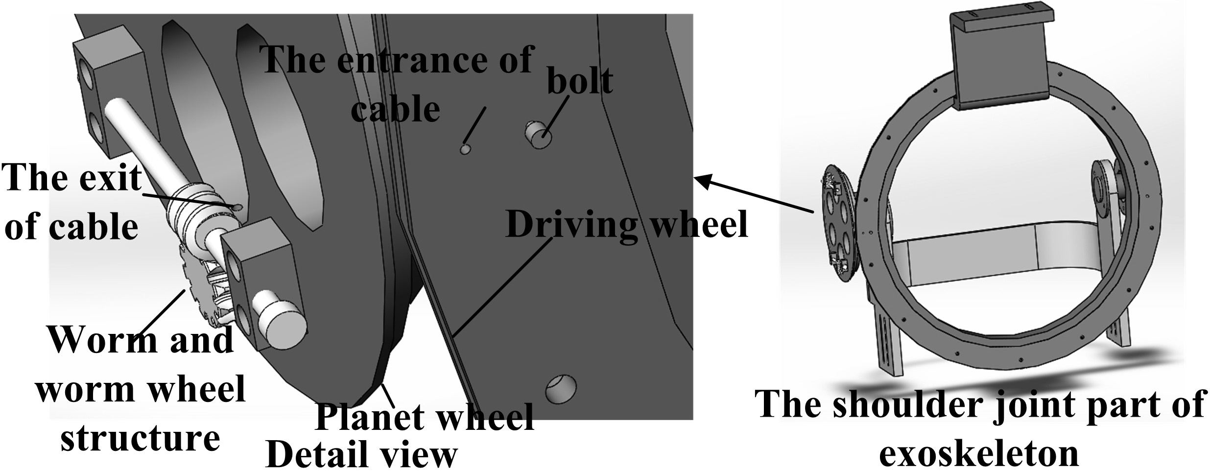
Figure 7.
The workspace of the exoskeleton.
According to Fig. 4a and c, the relationship between
(6)
Then, Eq. (5) can be re-expressed as follows:
(7)
In the situations illustrated in Fig. 5b, c and d,
2.4The pre-tensioner of the cable-driven mechanism
To ensure the reliability of the cable-driven mechanisms, the pre-tensioner should be examined. In this paper, the worm and worm wheel structure have been used as the pre-tensioner, which makes use of its self-locking characteristics [10]. When the lead angle of worm
3.Forward kinematics and workspace
According to Fig. 1 and Table 1, the transformation matrixes can be obtained using the following equation:
(8)
Where
4.Analysis of the transmission characteristics of the cable transmission system
In this section, the transmission characteristics of the cable transmission system are compared with the traditional gear transmission structure. The angle of transmission backlash is a primary indicator reflecting transmission characteristics, which is well if the angle of transmission backlash is small enough [11, 12]. The angle of transmission backlash of the cable transmission system is obtained as follows:
(9)
(10)
Where
If the wrist joint part is taken as an example, the value of some of the parameters are chosen as follows:
Figure 8.
The angle of transmission backlash.

5.Discussion and conclusion
In this paper, a newly-designed cable-driven upper limb exoskeleton (CABexo) based on epicyclic gear trains is described. Comparisons between CABexo and some of the existing exoskeleton systems show that it is able to meet the movement needs of most disabled and elderly individuals. As CABexo is a cable-driven exoskeleton, the transmission system is smoother and more stable than ARMin, RUPERT III, and IKO. The revolution motion and the spinning motion of the planet wheel form a 2-DOF coupled motion in CABexo. The upper arm, forearm, and palm of the user’s upper limb are driven by corresponding planet wheels, and, in a parallel mechanism, each planet wheel is supported and driven by two parts. Although the CAREX exoskeleton system is a cable-driven system, it is harder to control than CABexo with a parallel mechanism. In CABexo, all DC motors are placed on the backboard with an additional force transmission system, which makes the weight supported by the user’s upper limb lighter than ARMin and RUPERT III. Additionally, a pre-tensioner based on the self-locking characteristics of the worm and worm wheel structure is considered in order to ensure the reliability of the cable-driven mechanisms in CABexo. Future work will optimize the transmission forces system and design a reasonable control system.
Conflict of interest
None to report.
Acknowledgments
The work reported in this paper is supported by the Nuclear Science Foundation of China (Grant No. 2015BAF01B03).
References
[1] | Luy M, Flandorfer P and Giulio PD. Ageing in an aged society: experiences and attitudes of Catholic order members towards population ageing and older people. Ageing and Society. (2015) ; 35: (1): 1. doi: 101017/S0144686X13000421. |
[2] | Sugar TG, He J et al. Design and control of RUPERT: a device for robotic upper extremity repetitive therapy. IEEE Transactions on Neural Systems and Rehabilitation Engineering. (2007) ; 15: (3): 336. doi: 101109/TNSRE.2007.903903. |
[3] | Martinez F, Retolaza I et al. Design of a five actuated DOF upper limb exoskeleton oriented to workplace help. Proceedings of the 2nd; Biennial IEEE/RAS-EMBS International Conference on Biomedical Robotics and Biomechatronics; (2008) . doi: 101109/BIOROB.2008.4762788. |
[4] | Serea F, Poboroniuc M et al. Preliminary tests on a hybrid upper arm exoskeleton for upper arm rehabilitation for disabled patients. 2014 International Conference and Exposition on Electrical and Power Engineering (EPE 2014); (2014) . |
[5] | Antonio J et al. Online assessment of human-robot interaction for hybrid control of walking. Sensors. (2012) ; 12: : 215. doi: 103390/s120100215. |
[6] | Mao Y, Agrawal SK et al. Design of a cable-driven arm exoskeleton (CAREX) for neural rehabilitation. IEEE Transactions on Robotics. (2012) ; 28: (4): 922. doi: 101109/TRO.2012.2189496. |
[7] | Mao Y, Jin X et al. Human movement training with a cable driven arm exoskeleton (CAREX). IEE Transactions on Neural Systems and Rehabilitation Engineering. (2015) ; 23: (1): 84. doi: 101109/TNSRE.2014.2329018. |
[8] | Shao ZF, Tang X et al. Optimal design of a 3-DOF cable-driven upper arm exoskeleton. Advances in Mechanical Engineering. (2014) ; 1: . doi: 101155/2014/157096. |
[9] | Ball SJ, Brown IE et al. MEDARM: a rehabilitation robot with 5DOF at the shoulder complex. 2007 IEEE/ASME International Conference on Advanced Intelligent Mechatronics; (2007) . |
[10] | Sun H, Chen Z et al. Theory of Machines and Mechanisms (The 7th edition). High Education Press. Beijing, China; (2006) . |
[11] | Wang W et al. Machine design handbook (New edition). China Machine Press, Beijing, China; (2004) . |
[12] | Lu Y. Study on the principle and design method of the precise cable drive, PhD. Dissertation, National University of Defense Technology; (2013) . |
[13] | Reinkensmeyer DJ, Kahn LE, Averbuch M et al. Understanding and treating arm movement impairment after chronic brain injury: Progress with the ARM Guide. Journal of Rehabilitation Research and Development. (2000) ; 37: : 653. |

