
A goal-aligned coordinate system for invasion games
Abstract
Spatial locations of players and game devices are a fundamental data type in team-sports analytics. They are typically specified in Cartesian coordinates, but with varying conventions for the origin, orientation, and scaling. In invasion games such as football, basketball, or hockey, however, many markings are of fixed dimension even when the field of play is not, so that the game-specific meaning of locations does not scale uniformly. We propose an alternative coordinate system that accommodates variable field sizes by using the goals instead of a corner or the center of the field of play as frames of reference.
1Introduction
Spatio-temporal data is essential for sports analytics (Torres-Ronda et al., 2022; Memmert & Raabe, 2018; Zuccolotto & Manisera, 2020; Shea et al., 2017) and considerable effort is invested to achieve high levels of accuracy and precision (Linke et al., 2018; Rahimian & Toka, 2022). It appears that the seemingly straightforward specification of a data format convention has received comparatively less attention. Format specifications are, however, directly related to many data quality aspects and have an immediate impact on analytics (Karr et al., 2006).
For the purpose of this paper, we suggest to focus on the following three minimum requirements for spatio-temporal data in sports analytics:
(C1) Representation: Relevant relations such as durations (differences in time), distances (differences in location), and angles (differences in direction) should be preserved to ensure validity and facilitate meaningful operations on the data.
(C2) Interpretation: It is desirable that spatial and temporal indices are in direct correspondence with game-specific meaning to allow for human-readable spatial and temporal predicates.
(C3) Standardization: Like any other variable’s values, locations in space and points in (match) time should be comparable across match instances to ensure objectivity and facilitate reliable analyses.
Criteria C1 and C3 are actually necessary from a measurement-theoretic perspective (see, e.g., Hand 2010). It is therefore rather surprising that commonly used specifications of spatial data do not satisfy them. The main reason appears to be that in many invasion games the dimensions of the field of play are variable, whereas important field markings are of fixed dimensions. This leads to a trade-off between standardization on the one hand, and representation and interpretation on the other. Unlike the others, Criterion C2 is a matter of convenience and communicability, and thus a pragmatic objective.
Before proposing an alternative, goal-aligned, coordinate system in Section 4, we describe widely used specifications in Section 2, and outline in Section 3 how their respective combinations of standardized dimensions and choice of origin either enforce inconsistent and non-uniform scaling of coordinate axes, or hinder interpretability. Some conclusions are offered in Section 5.
For concreteness and readability, the discussion is focused on the case of association football (soccer), where analytics is rapidly gaining ground (Cefis, 2022). We emphasize, however, that both the problem and the proposed solution apply to any invasion game in which the dimensions of the field of play may vary, no matter whether this is due to tolerances in the laws of the game, imprecision, or exceptions granted for environmental conditions such as historic or multi-use arenas.
2The field of play
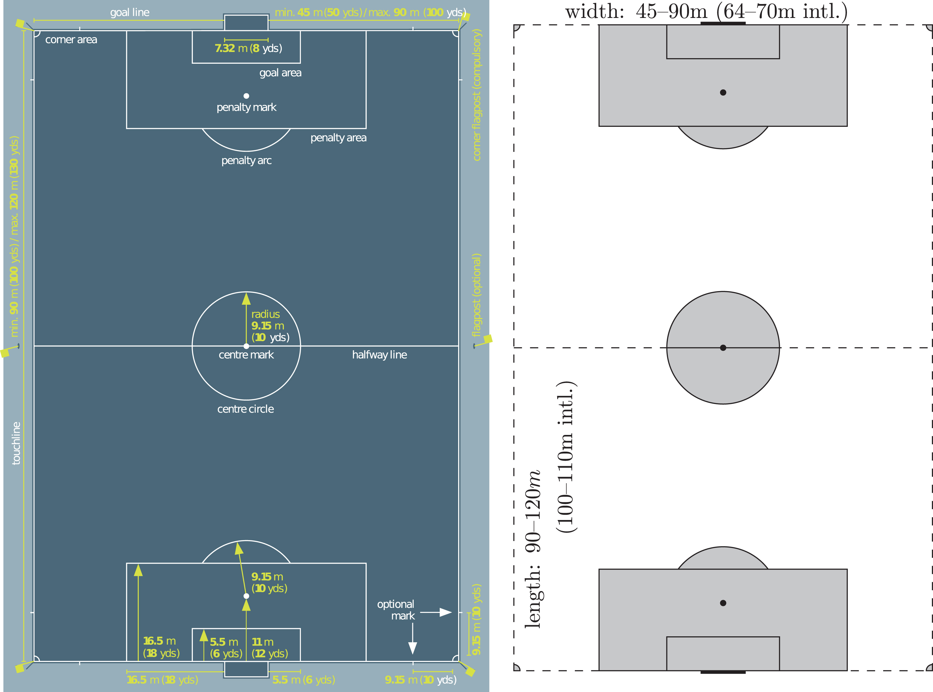
In association football (soccer), as in other invasion games, two teams attempt to score by moving a ball into the other team’s goal. The first of the IFAB Laws of the Game (The International Football Association Board, IFAB, 2022) specifies the field of play. Parts of this specification are depicted in Fig. 1.
Fig. 1
Field markings and their denominations in association football. Left: Specification diagram reproduced from the IFAB Laws of the Game (The International Football Association Board, IFAB, 2022), where an inset with the corner arc radius specification of 1m/1yd has been removed from the original for simplicity. Right: Simplified representation in which dashed lines indicate dimensions that are variable, whereas gray areas and solid lines have fixed areas and lengths. Restrictions for international matches are tighter, and the touchlines (vertical length) must be longer than the goal lines (horizontal width). Since length and width may vary independently, a wide range of aspect ratios is admissible.
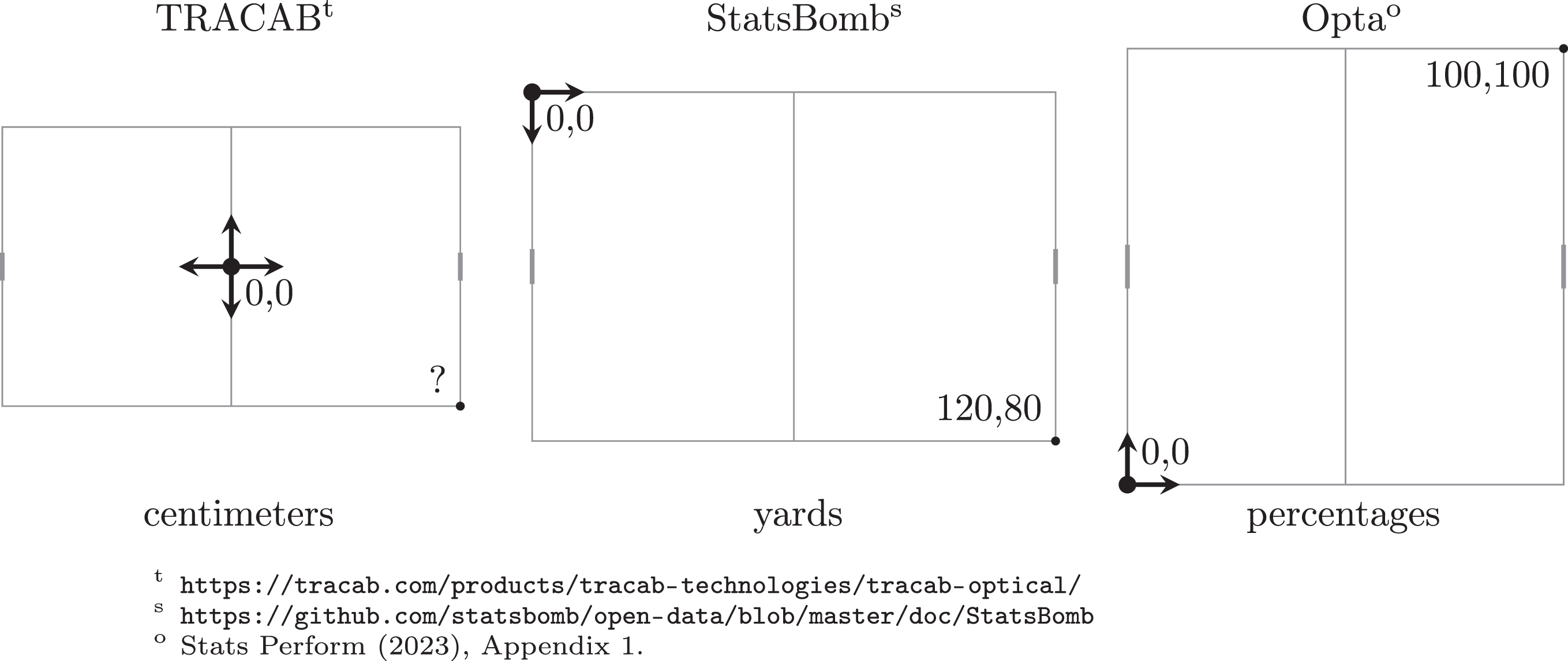
Data providers and analytics software use a variety of coordinate systems to identify locations on the field of play. As exemplified by the prototypical systems shown in Fig. 2, the majority of coordinate systems in use today are oriented horizontally (an aspect revisited in Section 5), and their origin is placed either in the center of the pitch or in the upper or lower left corner. Vertical axis orientation differs with the choice of origin, but the horizontal axis is generally either aligned with a team’s perspective (where the team in possession always plays, say, left to right) or fixed (for instance with respect to the technical area or the main stand). The scaling of axes is another source of variation, with metric, imperial, and relative units of length being the most common.
Fig. 2
Examples of typical coordinate systems used by data vendors with their respective units of length. Note that all of them are oriented horizontally, with goals left and right. In TRACAB’s system corner coordinates depend on length and width of the pitch, and in StatsBomb’s and Opta’s systems pitches are standardized so that their aspect ratios (length divided by width) are fixed to 1.5 and 1, respectively.
That this variety of approaches to representing locations continues to exist may be due in part to a lack of standards. While the Electronic Performance and Tracking Systems (EPTS) Standard Data Format specification put forward by FIFA standardizes many things, it does not prescribe a coordinate system (Fédération Internationale de Football Association, FIFA, 2021).
In the ChyronHego’s TRACAB coordinate system, game-specific meaning cannot be inferred directly from the coordinates of a location. Depending on whether a match between Liverpool and Chelsea is played at Anfield or Stamford Bridge (cf. Table 1), a ball located at 〈5100, 0〉 (i.e., 51m to the right of the center mark) is either inside or in front of goal, and a defensive foul committed at 〈 - 3200, 1000〉 either yields a penalty or not. This is in violation of the pragmatic Criterion C2 from the introduction, and results in the need to include pitch dimensions into the formulation of spatial predicates.
Table 1
Metric field dimensions in some well-known venues ordered by aspect ratio (i.e., length divided by width). All but the historical size of Valeriy Lobanovskyi Stadium and beautifully located Hennigsvær Stadion are within FIFA specifications for international matches, but exhibit differences in areas and aspect ratios. Entries in italics are extremes from the specifications in Fig. 1. More remarkable pitches are covered in Herman (2022)
| Field of play | home ground of | length[m] | width[m] | ratio |
| minimum aspect ratio | 90 | <90 | >1 | |
| maximum area | 120 | 90 | 1.33 | |
| Valeriy Lobanovskyi Stadiumk | FC Dynamo Kyiv | 100 | 75 | 1.33 |
| minimum aspect ratio (intl.) | 100 | 70 | 1.43 | |
| maximum area (intl.) | 110 | 75 | 1.47 | |
| Goodison Parkp | Everton FC | 100.5 | 68 | 1.48 |
| Anfield Stadiump | Liverpool FC | 101 | 68 | 1.49 |
| Coliseum Alfonso Pérezg | Getafe FC | 105 | 70 | 1.50 |
| The City Groundp | Nottingham Forest | 102.4 | 68 | 1.51 |
| Stamford Bridgep | Chelsea FC | 103 | 67.5 | 1.53 |
| Campo de Fútbol de Vallecasv | Rayo Vallecano | 100 | 65 | 1.54 |
| Craven Cottage | Fulham FC | 100 | 65 | 1.54 |
| standard | 105 | 68 | 1.54 | |
| Estadio Manuel Martí nez Valeroe | Elche CF | 108 | 70 | 1.54 |
| minimum area (intl.) | 100 | 64 | 1.56 | |
| Yankee Stadiumn | New York City FC | 100.6 | 64 | 1.57 |
| Unipol Domuss | Cagliari Calcio | 105 | 65 | 1.62 |
| Henningsvær Stadionh | Henningsvær IL | 100 | 60 | 1.67 |
| maximum aspect ratio (intl.) | 110 | 64 | 1.72 | |
| minimum area | 90 | 45 | 2.00 | |
| maximum aspect ratio | 120 | 45 | 2.67 |
kFC Dynamo (2023), https://fcdynamo.com/pages/stadion-dinamo-im-valeriya-lobanovskogo. pPremier League Handbook (2023/2024), https://resources.premierleague.com/premierleague/document/2023/08/31/132475d9-6ce7-48f3-b168-0d9f234c995a/PL_Handbook_2023-24_DIGITAL_29.08.23.pdf. sSerie A (2023), https://img.legaseriea.it/vimages/64ca2214/15-ImpiantiufficialiSerieATIM23-24.pdf. vRayo Vallecano (2023), http://www.rayovallecano.es/club/estadio. eMARCA (2014), https://www.marca.com/2014/01/01/en/football/spanish_football/1388600653.html. gUEFA (2010), https://www.uefa.com/womenschampionsleague/news/01e4-0e11e16ecba5-3e6a87c74324-1000–coliseum-alfonso-perez/. hNorges Fotballforbund (2023), https://www.fotball.no/fotballdata/anlegg/hjem/?fiksId=8307 nWall Street Journal (2015), https://www.wsj.com/articles/yankee-stadium-dimensions-cramping-new-york-city-fcs-style-1432860456
Ostensibly to aid interpretation, but possibly also because of the use of field markings in pitch registration approaches to data acquisition (Cuevas et al., 2020), StatsBomb’s and Stats Perform’s Opta specifications fix the coordinates of all corners of field markings. Although this ensures interpretable coordinates for predicates such as those above, we demonstrate in the next section why the combination of standardizing variable pitch dimensions and invariable field markings leads to violations of Criteria C1 and C3, which is even worse.
3The problem with standardizing pitch dimensions
As pointed out above, lengths and widths of football pitches may vary independently, so that aspect ratios can vary as well, whereas commercial data providers often use standardized dimensions, and thus fix an aspect ratio.
Conventional football pitch dimensions are 105m in length and 68m in width for an aspect ratio of 1.54. Unlike other metric dimensions such as the 9.15m center circle, these values do not result from the conversion of imperial units of measurement, but from the attempt of fitting a large rectangle with integer dimensions inside an Olympic-standard 400m running track. Some national competitions such as the French Ligue 1 (Ligue de Football Professionnel, Ligue 1, 2021) require all venues to adhere to these specifications. Standard dimensions are also a necessary condition to qualify for Categories 3 and 4 according to the UEFA Stadium Infrastructure Regulations (Union of European Football Associations, UEFA, 2018). Other dimensions are more prevalent, however: according to a national survey of sports facilities, more than half of all playing fields in Switzerland are smaller than 100m by 64m (Balthasar et al., 2013). Even top-level competitions such as the English Premier League or the Italian Serie A often grant exceptions for legacy venues. In the 2023/24 season, seven out of twenty clubs in the English Premier League have a home ground with non-standard pitch dimensions. Table 1 lists example venues from the highest levels of professional football and extreme cases allowed by the rules.
In the following subsections, we identify two major problems arising when locations on pitches of varying size and aspect ratio are mapped to standardized coordinates. We also discuss why these do not arise in the temporal domain.
The issues are formulated in terms of coordinate transformations that are covered in any textbook on geometry, but their implications are experienced more directly in computer graphics (Hughes et al., 2013) where the use of local coordinates systems, on which our alternative proposal in Section 4 is based, is commonplace as well.
3.1Non-similarity transformation
Angles and distances are elementary spatial relations that need to be represented accurately to facilitate analyses involving running speed, passes, shots at goal, and many other uses of spatio-temporal data.
Any transformation of the plane that preserves angles and distance relations (up to scaling) is called a similarity transformation and obtained from a composition of translation, rotation, reflection, and scaling. If a physical pitch and the standardized dimensions of a data specification do not have the same aspect ratio, as is often the case, standardization necessarily involves a non-similarity transformation.
As a consequence, angles and distances determined on standardized spatial data will misrepresent the actual ones to a degree. This is the case, for instance, in StatsBomb’s event data where straightforward tests confirm that, for instance, the length and orientation attributes provided for a pass are determined from its start and end location after standardization. They are therefore distorted if the actual pitch does not have the 1.5 aspect ratio of the company’s 120 × 80 square yards standard.
Vendors using more obviously unreal pitch dimensions such as the 100 × 100 percentage distances used for Opta instead provide angle and distance information computed before standardization. While this can be more accurate, it constrains any subsequent analysis to exactly those spatial relationships the provider cared to include.
3.2Non-homogeneous transformation
Even if the aspect ratio of a given pitch coincides with the standardized dimensions, i.e., scaling of the bounding rectangle is uniform, area variability conflicts with the fixed size of field markings.
Standardized expression of spatial predicates such as whether a location is inside the penalty area is supported by a fixed mapping of coordinates to markings such as goal posts, penalty marks, or the corners of the penalty areas. Typical examples are included in Fig. 3. Fixation of coordinates for certain markings may, in fact, sometimes be a byproduct of their use in playing field registration (Cuevas et al., 2020) rather than an attempt to guarantee interpretability.
Fig. 3
Example distortions of a pitch sized 105 × 68m2 arising from standardization including fixed points. Left: Fixing corners of penalty areas in StatsBomb’s system ensures that the penalty area is to scale, but other areas are enlarged. Right: Mapping corners of goal and penalty areas and penalty marks in Opta’s system leads to stretched peripheral intervals (scaling factor >1) of the horizontal coordinate and a compressed central interval (scaling factor <1). Due to additional fixed coordinates, the actual number of intervals is even larger, and corresponding non-linearities exist in the vertical dimension. Both issues arise in all such systems and are indeed unavoidable when pitch sizes can vary while some markings do not.
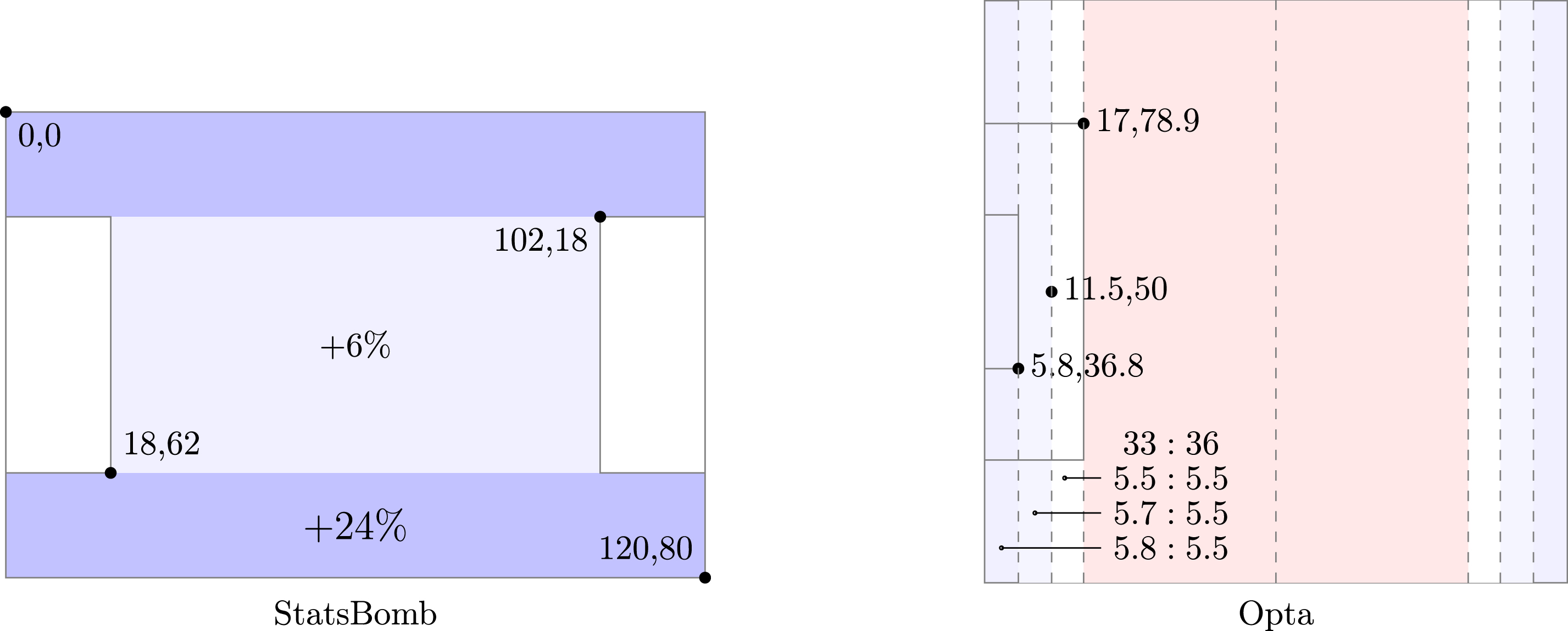
No matter the motivation, fixed locations of field markings imply that different areas of a pitch that is not to scale of a data provider’s specifications will be transformed non-homogeneously.
To rule out the possibility of uniform scaling of the entire pitch, it suffices to consider a penalty area. As an example of a space with fixed dimensions, consider the 16.5m × 40.32m= 665.28m2 penalty areas. They make up a variable percentage of the area of pitches with different size. At Coliseum Alfonso Pérez, the home ground of Getafe CF, they each covered 9.05% of the pitch which was 105 × 70m2 at the time of the 2010 Women’s Champions League Final (cf. Table 1). The 18 × 44 penalty areas of StatsBomb’s 120 × 80 standardized pitch each cover only 8.25%, despite the common 1.5 aspect ratio of the actual and the standardized ground.
To see that the issue arises not just with areas but even within a single dimension, consider fixed coordinates for penalty marks. In Stats Perform’s Opta specifications, for instance, penalty marks are fixed at coordinates 〈11.5, 50〉 and 〈88.5, 50〉. A difference of 11.5 units in the first coordinate therefore represents a length of 11m. Applying the scaling factor of
While piecewise linear and more general non-homogeneous schemes reduce the representation error of point locations, no transformation of the plane can preserve angles, areas, and distances across different pitch sizes when coordinates of field markings are fixed, which in turn is desirable for interpretable coordinates (Criterion C2) and simple spatial predicates (Criterion C3).
3.3Temporal dimension
Common specifications for the temporal dimension avoid the above issues because the only transformation they apply is translation by an offset.
Time is generally specified in multiples or fractions of a second, i.e., using the base unit of time in the International System of Units (SI), and with reference to either Universal Coordinated Time (UTC) or relative to the start of a match period. Given the starting times of match periods, i.e., an alignment of match time with actual time, temporal scales and reference points are easily transformed into each other without distortion or loss of information. Note that these starting times take the role of origins in a one-dimensional coordinate system, and that there is one such origin per match period.
If the temporal dimension was specified in the same way as the spatial, the duration of each period would be rescaled separately to fit a fixed time interval. By the 7th Law of the Game, a standard match lasts for two equal halves of 45 minutes, but at the discretion of the referee an allowance is made for time lost during each period. Similar to the variance in pitch dimensions, this results in a variable amount of added time, until recently about 2–7 minutes. If time were treated the way space is, the actual duration of each period would be rescaled (compressed) to fit an interval of the corresponding standard length.
The key decisions to note are that only rigid transformations (i.e., time shifts) are applied and that distinct reference points are used for each match period (i.e., their starting times).
4A goal-aligned coordinate system
The issues outlined in the previous section arise because the following two choices are pervasive in current specifications, but unsuited for the mixture of fixed and variable dimensions of field markings:
• Treating all pitches as if they were of standardized dimensions.
• Placing the origin of the coordinate system outside of the most important rigid components.
Below we propose a coordinate system that alters these two choices to meet the requirements stated in the introduction and to avoid the problems described in the previous section. While the resulting system may appear unfamiliar at first, the underlying decisions correspond directly to those commonly accepted for the temporal dimension.
To reflect the duality of attack and defense between two teams as well as the symmetry of the field of play, we propose to use the centers of both goals as two frames of reference, rather than a corner or the center of the pitch.
Before introducing the formal specification, however, we outline three conventions used in it. Although they serve standardization (Criterion C3), they are not required elements of our proposed coordinate system.
4.1Conventions
Invasion games are territorial and revolve around two special locations, typically the centers of two goals or other marks defended and attacked by either team. Therefore, the field of play generally has two symmetry axes, a longitudinal one intersecting the goals, and a lateral one perpendicular to it. The (opposing) directions of play for the two teams align with the longitudinal axis, because the teams are trying to close in on the other team’s goal. As a consequence, all common field-oriented spatial notions such as left and right, forward and backward, or high and low, align with the longitudinal axis when oriented according to the perspective of a team.
In football, it seems that the more frequent spectator perspective from the touchlines, which is also the (supposedly) non-partisan perspective of television broadcasts, may have led data providers to prefer horizontal pitch orientations and standardize only the direction of play, often from left to right. While the wider aspect ratio may also be a form factor on monitors and in print, vertical pitch orientation is more common in coaching materials (Wade, 1967; Zauli, 2003; Teoldo et al., 2022) and team meetings, because it reduces the dissonance between orientation during briefings and in matches.
In line with spatial terminology, tactical practice, and physical measurement we therefore adopt the following conventions:
1. Vertical pitch orientation with the two goals at the bottom and top.
2. A team-specific perspective with upward direction of play.
3. All coordinates specified in standard units of measurement for length.
4.2Definition
As argued above, we assume, without loss of generality, vertical orientation and a team-specific perspective. We next define a coordinate system that represents a location on the pitch not in one but two, complementary, ways. This redundancy is conceptual only, and does not affect storage requirements.
Since there is no single point of reference from which distances are invariant on pitches of different size, we instead use two reference points that together make every pitch location addressable in an interpretable way, independent of pitch size.
In invasion games, no two points are more characteristic references than the centers of the goals. With these as the origins of two related (local) Cartesian coordinate systems, we obtain two different expressions for the same location: while the x-coordinate referring to the lateral dimension is shared, the y-coordinate is either with reference to a team’s own goal line or the opposition’s goal line. In the following definition, the two reference points should be thought of as the goal defended and the goal attacked.
Definition 1. Let
1. a rotation that aligns the vertical axis with the vector from
2. a translation that moves the origin into either
A single location is thus equivalently expressed as either
If
Table 2
The orientations of the longitudinal coordinate axes in the goal-aligned coordinate system are chosen to allow straightforward conversion between perspectives of teams and goals they defend or attack
| focal team | |||
| goal cs | defends | attacks | |
| direction of play | focal team ↑ | x,
| x,
|
| opponent team ↓ | -x,
| -x,
|
4.3Properties
The goal-aligned coordinate system is designed in response to issues caused by standardizing pitch dimensions and using a corner or the center of the pitch as the origin. We therefore outline how some of the system’s properties address these issues. The arguments are organized along the criteria set out in the introduction.
(C1) Representation. In measurement theory, a representation is a mapping between an empirical structure (such as space) and a numerical structure (such as a coordinate system) that preserves a set of relevant relations (such as distances). By using multiples of the same unit of length as coordinates in each dimension, we ensure that dimensions are on the same scale, and thus a direct correspondence between computations in the coordinate system and spatial properties such as distances, areas, and angles.
The inverse problem of locating a point on the pitch that is represented by goal-aligned coordinates only requires knowledge of the association of the two reference points with the actual centers of goals on the pitch. Note that currently used coordinate systems require the same to determine the orientation of the axes.
Because of this straightforward inversion there is no need to reverse what potentially was a non-similarity transformation applied during pitch standardization or to precompute spatial relations before standardizing coordinates. It is interesting to note that
(C2) Interpretation. If a player is fouled in location
For the most important spatial predicates, one of the two vertical coordinates in a goal-aligned coordinate system will allow for a direct interpretation with no transformation necessary. Examples are given in Table 3. Only for locations in touch (horizontally out of bounds), the width of the field is needed as the second contextual parameter.
Table 3
Sample spatial predicates for a location
| spatial predicate | interpretation | context information |
| |x|≤20.16 ∧
| inside opposition penalty box | penalty area 40.32 × 16.5m2 |
| x = 0 ∧
| on own penalty mark | 11m from goal on vertical axis |
| |x|≤3.66 ∧
| inside own goal | goals are 7.32m wide |
|
| past either goal line | |
|
| halfway across pitch | |
|
| on center mark | |
|
| d meters into opposition half | |
|
| inside center circle | radius of 9.15m |
|
| on pitch | for a pitch w meters wide |
(C3) Standardization. It goes without saying that coordinates should be assigned consistently over the duration of a match. For analyses covering multiple matches of a team or a player, or comparing locations of different players in different teams and different matches on different fields of play, additional requirements need to be satisfied to ensure commensurability. Standardized dimensions are one way of ensuring that locations appear comparable relative to a corner of a rectangular pitch.
We have seen in the previous section that variable aspect ratios, however, necessitate non-similarity transformations. As a consequence, spatial analyses such as the area around a player when receiving the ball or the distance of defenders from the attackers they mark can be distorted differently on the same pitch (Fig. 3) as well as across pitches (Table 1). This does not happen with goal-aligned coordinates.
Similarly, shot locations from multiple matches are easily aggregated and placed on a common shot map when represented with the attacking goal-aligned coordinate. Contrast this to a coordinate system with the origin at the center, where each shot location needs to be translated because the goal line may be at varying distance from the halfway line.
With goal-aligned coordinate systems, no scaling or other adjustments are needed, except when changing the unit of length from meters to, say, centimeters or yards. Instead, we only select the longitudinal coordinate corresponding to the analytic interest at hand. For defensive actions, for instance, this will generally be the vertical coordinate with reference to the analyzed team’s own goal. For an analysis of counterpressing, however, it may be more appropriate to consider the opposition goal as the reference point.
4.4Design choices
Given the above properties, two choices in the design of goal-aligned coordinate systems may appear questionable.
For instance, one might argue that flipping the orientation of the vertical axis for coordinates with reference to the opposition goal leads to a higher degree of symmetry and avoids the use of negative coordinates for the most part. From a conceptual point of view, however, this would lead to a mixing of both teams’ perspectives and, more importantly, it would make the comparison of difference vectors (in particular between origin and destination of a pass or run) less straightforward. By retaining the orientation of the vertical axis, results are independent of the choice of vertical coordinate when computing difference vectors or angles.
The main question regards the conceptual redundancy of goal-aligned coordinates. Since
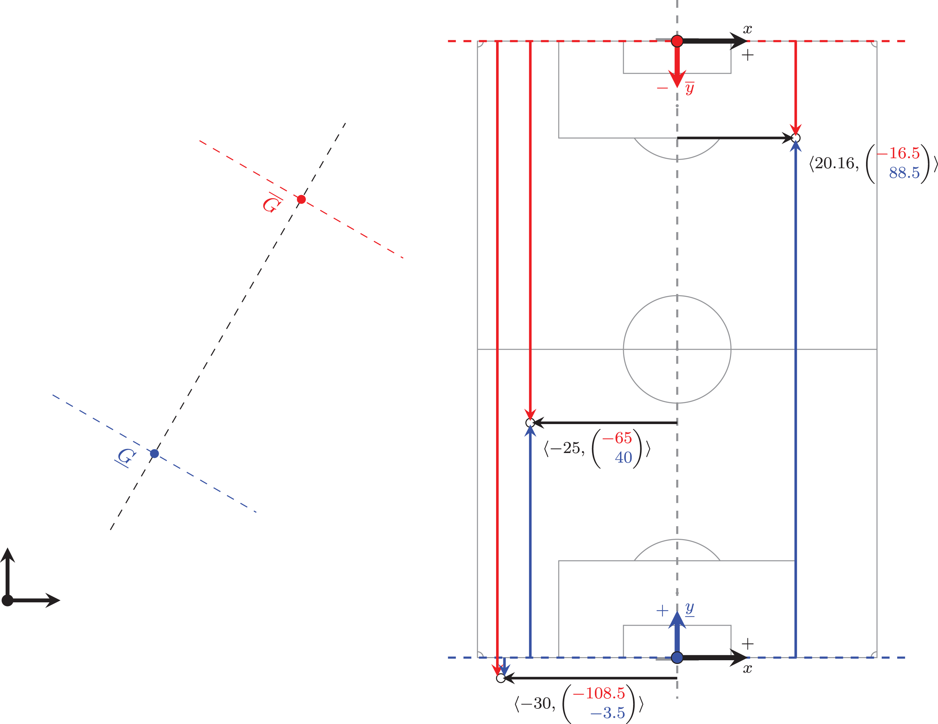
Fig. 4
Goal-aligned coordinate systems are defined by aligning the axes of a Cartesian coordinate system with the line through two given points,
4.5Pragmatic aspects
With respect to spatial features, the only variable elements in the specification of a field of play are its dimensions ℓ × w and the unit s of measurement for length. We refer to these three values as contextual data. While it is good practice to include them in any data set, they may also be implied by sport-specific convention, e.g., ℓ=105, w = 68, and s = 1m (one meter).
For storage and transmission of two-dimensional spatial data in goal-aligned coordinates, no additional space is therefore required, provided that contextual data are included or implied. If contextual data is implied, the only essential difference between goal-aligned coordinates and the TRACAB system is the choice of origin. Similar to the systems in StatsBomb and Opta data, we may choose to store player locations with reference to their own goal, and the ball with reference to the home team’s goal.
For in-memory representation, however, it will be more flexible to define views on locations. In an object-oriented programming environment, locations can be encapsulated in a class that references pitch characteristics and offers methods to access the location in any of the four perspectives with respect to either goal as attacked or defended by either team. This is particularly convenient when the analytic interest is in relations between players of opposing teams, such as pressures, pitch control, or the extraction of marking networks. Where relevant for additional context, we may also refer (explicitly or implicitly) to match data that includes the associations of the physical goals with each team in each period.
In writing, locations on a pitch can be specified as usual in a pair of 〈x, y〉-coordinates if the perspective (which team, which goal?) is clear from context. Like most of the action, many tasks in analytics do not require knowledge of pitch dimensions, but are in reference only to one of the goals. Examples include shot maps, expected goals, height of the defensive line, and passes into the final third. Others such as team shape, pass lengths or angles, and line-breaking passes are translation invariant and may not need a reference point at all.
5Conclusion
We have proposed an alternative coordinate system for locations on the field of play in invasion games. Using the centers of the goals associated with either team as the points of reference, it accommodates variable dimensions of the field of play even when other markings are invariant. In addition to the formal advantages this entails, goals are the most significant reference points in an invasion game, anyway. Extension to three-dimensional data is straightforward, as long as the same unit of length is employed when adding height above the field of play as another dimension.
Although we used association football as the running example, the same situations arise in other sports. According to the rules set by the respective governing bodies, tolerances are allowed for the dimensions of the field of play in, for instance, Australian-rules football (AFL), ice hockey (IIHF), or grass polo (FIP). In other sports, there may be no such allowances in any one rule book but different associations specifying different dimensions. In basketball, for instance, court dimensions and even aspect ratios differ between FIBA and the NBA.
Goals are not only intuitively the most significant points of reference in an invasion game. Unlike coordinate systems commonly used today, our goal-aligned alternative satisfies all three criteria stated in the introduction and should therefore be considered in the quest for a standard.
Acknowledgment
I am grateful to two anonymous reviewers for helpful and supportive comments.
References
1 | Balthasar A. , Bieri O. , Laubereau B. , Arnold T. , Rütter H. , Höchli C. , Rieser A. , Stettler J. , Wehrli R. , 2013, Sportanlagenstatistik Schweiz 2012. Kurzbericht, Bundesamt für Sport BASPO, Magglingen. |
2 | Cefis M. , (2022) , Football analytics: A bibliometric study about the last decade contributions, Electronic Journal of Applied Statistical Analysis, 15: (1), 232–248. |
3 | Cuevas C. , Quilón D. , García N. , (2020) , Automatic soccer field of play registration, Pattern Recognition, 103: , 107278. |
4 | Fédération Internationale de Football Association, FIFA, 2021, EPTS Standard Data Format. URL: https://www.fifa.com/technical/football-technology/standards/epts/research-development-epts-standard-data-format. |
5 | Hand D.J. 2010, Measurement Theory and Practice: The World Through Quantification, Wiley. |
6 | Herman R. 2022, Remarkable Football Grounds: An Illustrated Guide to theWorld’s Perfect Soccer Pitches, Pavilion Books, London. |
7 | Hughes J.F. , Dam A.V. , McGuire M. , Sklar D.F. , Foley J.D. , Feiner S.K. , Akeley K. 2013, Computer Graphics: Principles and Practice, 3. edition edn, Addison-Wesley, Upper Saddle River, New Jersey. |
8 | Karr, A.F. , Sanil, A.P. , Banks, D.L. , (2006) , Data quality: A statistical perspective, Statistical Methodology, 3: (2), 137–173. |
9 | Ligue de Football Professionnel, Ligue 1, 2021, User’s manual: The pitch. URL: https://www.ligue1.com/Articles/NEWS/2021/09/07/user-s-manual-the-pitch |
10 | Linke, D. , Link, D. , Lames, M. , (2014) , Validation of electronic performance and tracking systems EPTS under field conditions, PLOS ONE, 13: (7), e0199519. |
11 | Memmert, D. , Raabe, D. , 2018, Data analytics in football: Positional data collection, modelling and analysis, Routledge, Boca Raton, FL. |
12 | Rahimian, P. , Toka, L. , (2022) , Optical tracking in team sports: A survey on player and ball tracking methods in soccer and other team sports, Journal of Quantitative Analysis in Sports, 18: (1), 35–57. |
13 | Shea, S. , Baker, C. , Custance, C. , 2017, Hockey Analytics: A Game-Changing Perspective, CreateSpace Independent Publishing Platform. |
14 | Stats Perform, 2023, Sports Data Soccer API - Match Events (M3) Feed. URL: https://documentation.statsperform.com/docs/rh/sdapi/Topics/soccer/optasdapi-soccer-api-matchevents.htm |
15 | Teoldo, I. , Guilherme, J. , Garganta, J. , 2022, Football Intelligence: Training and Tactics for Soccer Success, Routledge, New York. |
16 | The International Football Association Board, IFAB, 2022, Laws of the Game 2022/23. URL: https://www.theifab.com/lawsof-the-game-documents/ |
17 | Torres-Ronda, L. , Beanland, E. , Whitehead, S. , Sweeting, A. , Clubb, J. , (2014) , Tracking systems in team sports: A narrative review of applications of the data and sport specific analysis, Sports Medicine - Open, 8: (1), 15. |
18 | Union of European Football Associations, UEFA, 2018, Stadium Infrastructure Regulations. URL: https://documents.uefa.com/r/8EF5wwwZzvgRyjrEnIjmw/root |
19 | Wade, A. , 1967, The F.A. Guide to Training and Coaching, Heinemann, London. |
20 | Zauli, A. , 2003, Soccer: Modern Tactics: Italy’s Top Coaches Analyze Game Formations Through 180 Situations, Reedswain Publishing, Spring City. |
21 | Zuccolotto, P. , Manisera, M. , 2020, Basketball Data Science: With Applications in R, 1st edition edn, Chapman and Hall/CRC, Boca Raton. |


