
10Boron-film-based gas detectors at ESS
Abstract
The development of detectors for the European Spallation Source is an important parallel element to the effort put into the design and construction of the neutron source and instruments. The 10Boron-film-based detector developments that started over a decade ago as basic detector concepts have now reached technical maturity after intense prototyping work and numerous testing campaigns. Several of the ESS beamlines that will soon enter the commissioning phase started welcoming the detector systems built with the 10B-film converter technology. The real-size demonstrators evolved in the last 2–3 years into a diverse suite of gas proportional counters for use in diffraction, reflectometry and small-angle scattering studies in spite of the operational complexity posed by the requirements for large-area coverage, low material budget and robustness for operation in the high-flux and high-radiation environment of ESS. The detectors are now being shipped to ESS or undergoing the last performance and calibration tests before being handed over to the instrument teams for installation in the host beamlines. A common feature of these detector systems is the very large number of readout channels that they are instrumented with in order to fulfill the demanding requirements for sensitivity, spatial resolution and count-rate capability. Across all of the detector types that will operate at ESS, the integration, testing and commissioning of the read-out technologies and software tools for data reduction, calibration and analysis are the focus of the detector and integration teams. These will yield a wealth of knowledge about their operation as well as initial results on the in-situ performance, a very important asset to ensure rapid commissioning of the detectors when neutrons from the ESS source become available. In this paper we will give an overview of the 10B-film-based detector technologies included in the ESS detector suite that are currently facing the transition from the production phase to installation and integration with the other beamline components, which comes with its own specific challenges of both organizational and technical nature.
1.Introduction
The detector technologies employed at existing and upcoming neutron scattering facilities must have excellent performance in order to fully exploit the performance of the neutron source. As such, the selection process for the set of instruments currently under construction at ESS Lund included intense discussions focussed on translating the ambitious science goals outlined in the proposals into instrumentation requirements, including detectors, and identifying the design, construction and timeline challenges. The worldwide shortage of 3He-gas that preceded the instrument selection process constituted a serious threat to the capability to build the detectors that address appropriately the scientific challenges and added great uncertainty and risk to the ESS capital envelope. Around year 2010 an international group of detector experts representing the main neutron scattering facilities in the world initiated a common effort with the goals of performing an analysis of the technical requirements for future experimental stations in terms of detectors, assessing the performance of existing technologies and discussing the possible upgrades or replacements [82]. As a consequence of the 3He crisis, a number of national funding agencies and European programmes allocated funds to the optimization of the current technologies and pushing their performance limits as well as to exploring new concepts by making use of the latest innovations in materials, fabrication and processing techniques. These initiatives were instrumental in providing the fundamental and vital technological contributions that formed the scope for the baseline detectors that not only matched the requirements imposed by the instruments but were also compatible with the funds that were believed to be available for their construction. For ESS, the primary choice for the replacement of the 3He-based technologies has been decided to be gaseous detectors with a 10B solid converter [28,45]. In the following years, all efforts focussed on demonstrating the suitability of the new detector concepts for particular applications as well as engaging with the user community and presenting them with the strategy to oversee this technological transition.
Table 1
The detector technologies for the initial ESS instrument suite
| Instrument | Application | Converter | Detector technology | In-Kind partner, Supplier |
| LoKi | SANS | 10B film | PSD | ISIS/PTI |
| DREAM | Powder Diffraction | 10B film | MWPC | FZJ (CDT) |
| Odin | Imaging | 6Li scintillator | TimePix3 | ASI |
| BIFROST | Indirect Spectroscopy | 3He gas | PSD | ILL/CEA Saclay |
| Testbeamline (TBL) | Testing | 3He gas, 10B film, 6Li scintillator | MWPC, PSD, TimePix3, CMOS | various |
| NMX | Macromolecular cristalography | 157Gd | Micropattern (GEM) | ESS |
| Estia | Reflectometry | 10B film | MWPC | ESS |
| BEER | Strain scanning | 10B film | MWPC | Hereon |
| MAGiC | Single-crystal diffraction | 10B film | MWPC | FZJ (CDT) |
| CSPEC | Direct Spectroscopy | 3He gas | PSD | ILL |
| SKADI | SANS | 6Li scintillator | Anger camera | FZJ |
| Freia | Reflectometry | 10B film | MWPC | ESS |
| Miracles | Indirect Spectroscopy | 3He gas | PSD | Baker Hughes (Reuter-Stokes) |
| Heimdal | Powder Diffraction | 10B film | MWPC | FZJ (CDT) |
| Vespa | Spectroscopy | 3He gas | PSD | Baker Hughes |
| T-REX | Direct Spectroscopy | 10B film | MWPC | ESS |
| Beam monitors | all | 3He gas, 10B film, 235U | MWPC, PSD, IC, Micropattern | various |
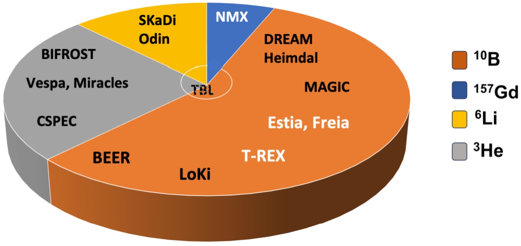
An overview of the initial ESS suite of 16 instruments including a Test beamline [5] and the detector technologies used by these are presented in Table 1 and represented graphically in Fig. 1. More than half of the instruments (9 as of 2023) will employ 10B-based gas detectors for the detection of the scattered neutrons. These detectors will be a combination of Multi-Wire Proportional Counters (MWPC) with flat cathodes and sealed gas tubes. The initial suite of powder and single-crystal diffractometers, the strain scanner, the reflectometry instruments and possibly one of the chopper spectrometers will operate exclusively with 10B-film-based MWPCs. 3He detectors, exclusively gas tubes, will also be used by 4 of the 5 spectroscopy instruments selected for construction. The Test beamline, which will be used to evaluate the early-days performance parameters of the accelerator and neutron source and for the testing, integration and calibration of the instrumentation developed in-house or delivered by partners [5], will use a set of technologies consisting of commercial detectors such as 3He tubes and TimePix cameras and detectors developed and built in-house. The second SANS instrument and the imaging station will rely on 6Li-based scintillator detectors. For all instruments, regardless of the technology employed, the installation of the detectors will follow a staged approach, i.e., only a part of the detector system will be available for operation during the cold and hot commissioning of the source and instruments [5].
Fig. 1.
Graphical representation of the distribution of the detector technologies employed by the ESS instruments. The instrument names marked in white will make use of Boron-based detector technologies developed at ESS. See Table 1 and text for more details. (For the color version of this figure, the reader is referred to the web version of this article.)
The ESS instrument projects are now in different stages of implementation. The first 5 instruments presented in Table 1 are in the most advanced phase of execution and are expected to complete the construction phase in the summer of 2024 (the so-called ‘Tranche 1’ instruments). Both the SANS instrument LoKI and the diffraction beamline DREAM will operate with 10B-based large-area detectors designed and built by commercial and in-kind partners. Thus, these two instruments will be the first in the world to demonstrate that the 10B-film-based detector technology not only meets the requirements for SANS and powder diffraction neutron scattering applications, respectively, but also integrates and operates smoothly in large-scale installations.
In this paper we will present the concept of operation of 10B-film-based gas detectors and discuss the most important use cases for the ESS instruments. We selected for presentation two of the most important in-house detector developments, namely Multi-Blade (Section 4.1) and Multi-Grid (Section 4.2), the technical solutions developed for reflectometry and direct spectroscopy applications, respectively. The Boron-coated straws and the JALOUSIE detectors, designed and manufactured by external partners in collaboration with commercial companies for use in SANS applications and diffraction experiments are described in Sections 5.1 and 5.2, respectively. We will not attempt a complete review of the intense work invested in the last decade into taking these from the prototyping stage and technology demonstrators to turn-key detector systems, but generally rely on previously published papers and other material. In this paper we will focus on the current status of these detector projects that are now transitioning from the construction to installation phase and start of operations.
2.Thermal neutron detectors
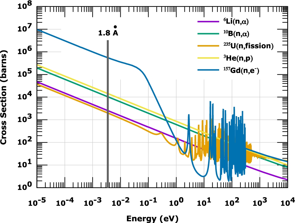
Detection of neutral radiation such as photons and neutrons relies on a conversion mechanism that yields charges in the sensitive volume of the detector. As such, cold, thermal and epithermal neutrons are detected through the daughter products of the prompt capture reaction between the neutrons and a material with a large absorption cross-section within a very wide band of energy. The materials that work well as neutron converter media are shown in Fig. 2. At normal temperature and pressure, these materials are available in either solid or gaseous form, which, together with the requirement for the solid angle covered by the detector, cost and workability, determine their area of applicability. For example, solid compounds containing the 6Li isotope, and to a lesser extent 10B, are most often employed as the neutron-sensitive component in scintillation materials (e.g. cerium-doped lithium glass (GS20) and ZnS(Ag)/6LiF). 157Gd has somewhat limited applicability due to the high sensitivity to gamma radiation. 235U is mostly used in small-size detectors such as beam monitors (e.g., fission chambers) which require only a tiny amount of converter material. 10B is mostly and 3He exclusively employed in gas detectors.
Fig. 2.
Absorption cross-sections for the isotopes most frequently used in the shielding and detection of cold and thermal neutrons. The plot was generated by using the Plotting Tool for ENDF (Evaluated Nuclear Data File).
The 3He gas shortage for neutron detection has made the 10B-film-based gas detectors the replacement technology of choice for large-area detectors for use in neutron scattering applications. Same as the 3He gas detector, the new generation of thermal neutron detectors based on solid converters follow the basic gas-detector physics principles, which are well understood [70]. Nowadays thermal neutron detectors employing solid converters are available in a variety of sizes and shapes, the most common ones being tubes and rectangular counters with flat surfaces. In the following paragraphs, we will describe the most common features related to the operation of gas detectors with solid converters. We will consider here only the case of 10B neutron converter, but the physics and operation principle of the 6Li-based gas detectors are very similar.
Fig. 3.
(a) Working principle of a 10B-film based gas detector (left panel) and a 3He tube (right panel) showing the basic trajectories of the reaction products denoted generically as (1) and (2). For the 10B-based detector the converter layer is drawn in blue. Signals are generated by the trajectories that allow the reaction products to deposit energy in the gas medium. The orange lines terminating in the center of the tubes represent the electric drift lines. The green circles represent the equipotential field lines. Pictures are not at scale. (b) Left: Calculated detection efficiencies for
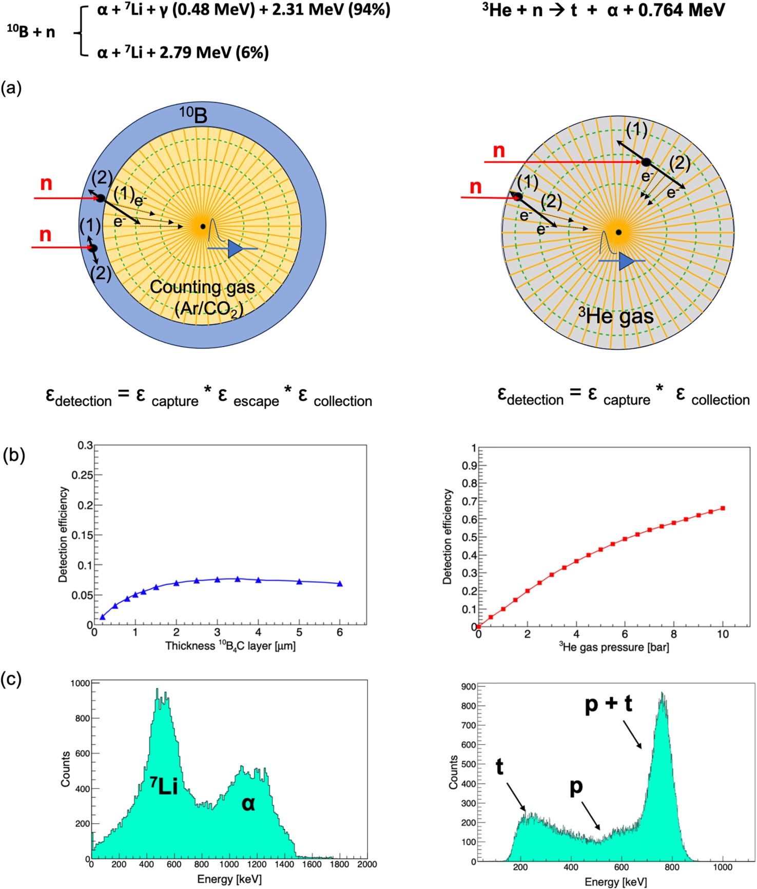
Figure 3(a) shows the capture reactions responsible for the neutron detection and the working principle of a tube-shaped Boron detector side-by-side with the 3He counterpart. In the Boron detector, thermal neutron detection is provided by a thin solid layer of 10B or a material enriched with 10B, such as 10B4C, deposited on the inner sides of a tube filled with a counting gas. The role of the counting gas is to enable the ionization and charge collection processes. The successful detection of the neutron requires a capture reaction with the 10B isotope to take place in the converter and one of the reaction products to reach the gas medium with sufficient energy to produce a signal above the threshold set for the readout circuitry. Unlike the 3He gas detector, the Boron-film based ones typically utilize only one of the reaction products in the detection process. The other one is emitted in the opposite direction following the conservation of momentum and it is absorbed either in the converter material or the substrate as shown in Fig. 3(a). The two processes involved in neutron detection, capture and escape, rely on conflicting requirements for the thickness of the converter. An efficient absorption requires several microns of converter material (wavelength-dependent), while a thin layer favors the escape of one of the reaction products. The product of the two probabilities gives the conversion efficiency, which, as seen in the left panel of Fig. 3(b), never becomes larger than 10% for thermal neutrons. A thick layer increases the probability for both reaction products to be entirely absorbed in the converter, thereby, not producing a measurable event. In the 3He tube, represented in the right panel of Fig. 3(a), the 3He gas plays both the role of the neutron converter and counting gas, therefore the detection efficiency is determined only by the conversion and charge collection processes.
The final step in the detection process with both detector technologies is the collection of the charge generated through the ionization of the gas. This is achieved by applying an electric field on the anode wire located in the center of the tube. The primary electrons will be accelerated and drift toward the wires in predetermined paths given by the electric field. These trajectories are represented in Fig. 3(a) by the black arrows. At a few microns away from the wire the electric field is so intense that it gives rise to secondary gas ionization called gas amplification [70]. The electron cloud generated in this secondary ionization process will be collected by the anode wire and give rise to an electric pulse that is still proportional to the energy deposited in the gas. In a gas tube, which has perfect symmetry around the anode wire, the charge collection efficiency is close to 100%. In a rectangular gas cell, the electric field is strong at short distances close to the wire and weaker close to the corners of the cell. Reduced collection efficiency is expected close to the corners of the cell due to the wall effect and to a higher probability for the electrons to interact and recombine with electronegative impurities in the gas, such as O2.
Shown in Fig. 3(c) are the neutron response pulse-height spectra calculated with the GEANT4 simulation software version 11.0.2 [1] for the two detector technologies depicted in Fig. 3(a). Same as the 3He-based gas detectors, gas counters based on a solid converter are insensitive to the energy of the incoming neutron. The pulse-height spectra of the thermal neutron detectors are a measure of the amount of energy deposited by the conversion products in the gas, which depends on their trajectory and emission site (i.e., distance from the gas interface in the case of the 10B-film based detectors and distance from the detector wall for the 3He counters). For the 10B-based detectors the pulse-height spectrum contains deposited energies ranging from almost zero up to the full energy of the highest-energy reaction product. The consequence of such distribution is the disappearance of the valley observed below 200 keV for the 3He-tube which provides the separation between the neutron and gamma signals observed when both detector technologies are operated at low gas gain (<10). The requirement for the best achievable spatial resolution imposed by the physics cases is fulfilled by operating the tubes at gas gains of 100 or higher, which spoils the energy resolution of both detectors and makes the neutron-gamma separation less obvious even for the 3He gas counters [69]. However, this effect is more significant in the 10B-film-based detectors and leads to slightly poorer neutron-gamma discrimination and lower neutron detection efficiency for this technology [75].
2.1.Orthogonal versus inclined geometry of the Boron converter layers
Fig. 4.
The general concept of multi-layering planar solid converters in order to increase the detection efficiency. The Boron converter is drawn in red and the Aluminium substrate is shown in blue. The direction of the incoming beam and the beam transmitted through each layer in the stack is shown by the black arrows. Please note that in order for both arrangements to work as gas counters anode wires need to be inserted between each two consecutive layers. These were not included in the drawing for simplicity. (a) Multi-layering in orthogonal geometry. (b) GEANT4 simulation of the detection efficiency for incident neutrons with wavelengths 1, 2.5 and 5 Å as a function of the number of double-sided converter layers in the stack each having a thickness of 1.2 μm. The scattering of the neutrons by the Aluminium substrate is accounted for by the model. (c) Same as in (a) but with the conversion layers titled by an angle α (defined relatively to the neutron beam, not to the perpendicular to the surface of the layers). The inset is a magnification of the region where the incoming neutron ‘sees’ the effective thickness, denoted as
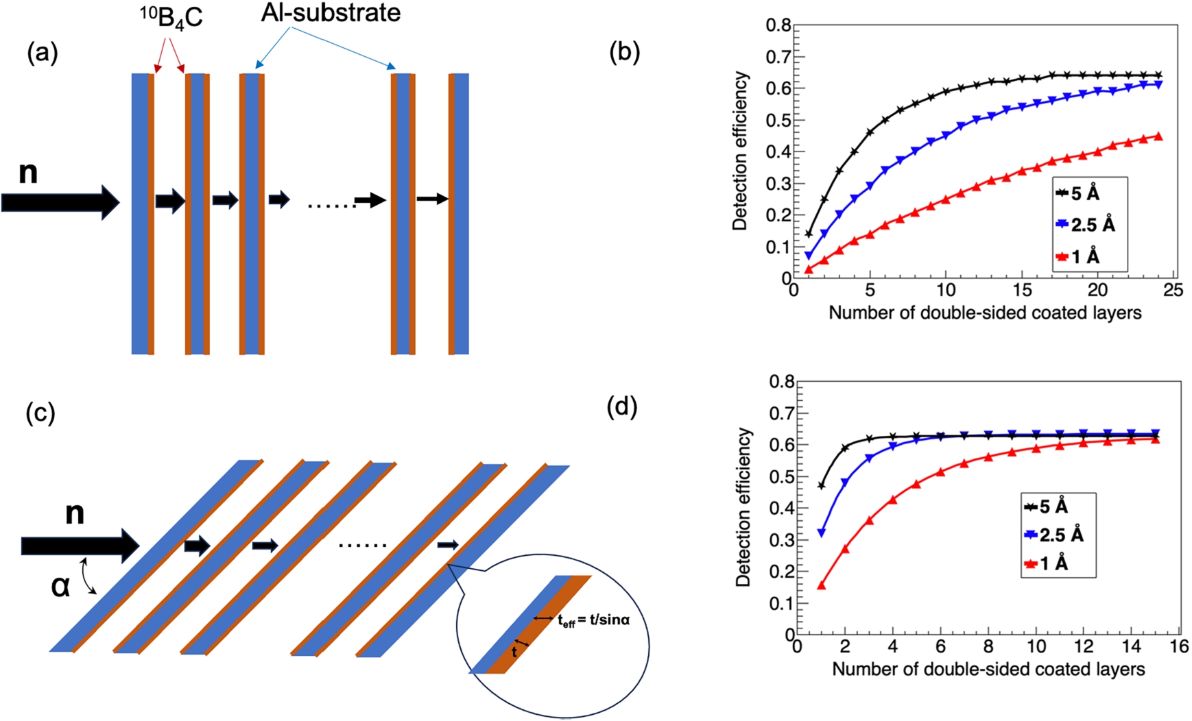
Fig. 5.
Cartoon showing the effects on spatial resolution and rate capability for a beam of neutrons with a spot ϕ impinging on a gas counter containing only one converter layer, drawn in red, and operating in (a) orthogonal geometry and (b) inclined geometry. The crosses mark the anode wires located halfway between two flat cathodes. The wires are numbered from 1 to 7. The orange lines starting from the anode wires represent the electric field lines that enable the collection of the ionization electrons generated by the reaction products escaping the converter layer. The wire pitch and the distance between the coated cathode and the wire grid are the same in both cases.
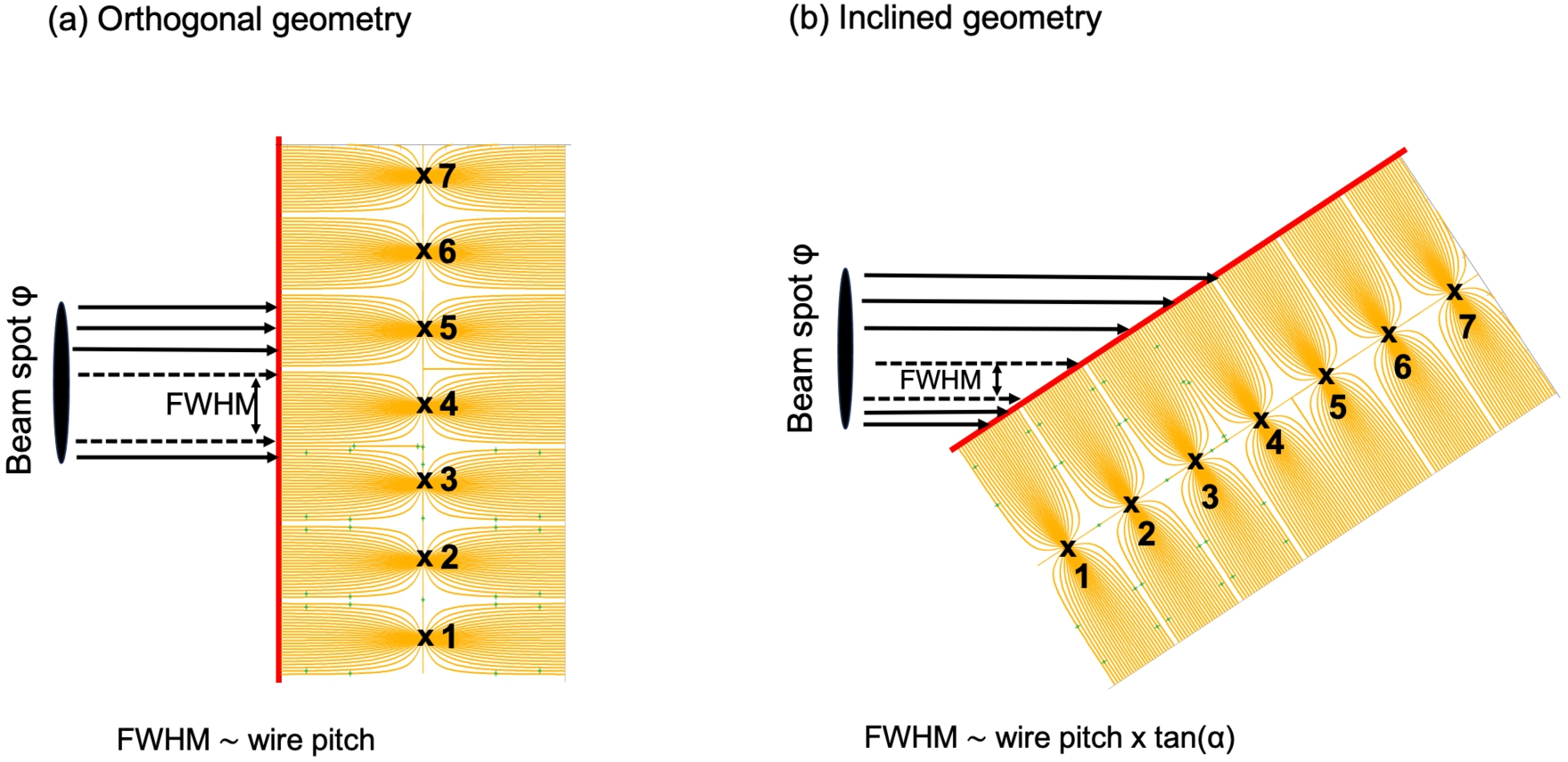
The disadvantage of thermal gas detectors with solid converters is the low efficiency of a single layer, which for thermal neutrons is typically ∼5% for a single planar Boron-layer or ∼10% for a tube. The equivalent in the detection efficiency of a pressurized 3He-tube can only be achieved by stacking alternating converter-ionization volume layers or coated tubes, which give the incoming neutrons the possibility to interact multiple times with the converter material until captured by the 10B nuclei. A possible arrangement is pictured in Fig. 4(a) for conversion layers with a planar surface. The number of layers in the stack depends on the desired efficiency and the range of neutron energies of interest. Analytical calculations and numerous simulations have shown that around 20 double-sided coated Boron layers (i.e., substrates coated on both sides) are required in order to achieve a detection efficiency of around 50% for thermal neutrons, as shown in Fig. 4(b) and discussed in detail in Refs. [61,75]. This number can be significantly reduced if the layers can be arranged such that the angle of incidence of the neutron on the converter becomes 10° or smaller, see Fig. 4(c) (note the convention used here that a 90° incidence angle corresponds to normal- and 0° to grazing-incidence). Geometrically, by inclining the Boron layer at an angle α with respect to the direction of the incoming neutron beam, the conversion efficiency increases because the effective neutron absorbing film thickness is increased by a factor proportional to
The multilayering in the B-film based detectors can be regarded as an increase in the granularity of the detector, the solution to tackle the high flux challenge that several of the existing neutron scattering facilities have and all of the new ones are expected to face. Each converter layer acts as an independent gas detector, provided the electrodes collecting the signals generated by the absorbed neutrons are read out independently. The multi-layer design will also provide some redundancy to the system in case of a wire/strip failure or even in the rare event of malfunctioning of an entire wire grid or stripped cathode. In this case the detection efficiency will be reduced, but the operation of the instrument is not affected significantly. However, multilayering also comes with several practical design aspects and key technological issues that need to be addressed before getting into the detailed design phase. The numerous conversion layers required in order to fulfill the efficiency specification add an extra dimension to the detector, which becomes significantly deeper than the 3He-based one. This leads to a dramatic increase in the number of readout channels, especially for those that are based on the inclined converter layer concept, and adds complexity to the signal-processing task. The operation of these detectors needs increased computing capabilities and more elaborate software tools for calibration, data reduction and analysis. Thus, the time allocated to R&D of any new design of a Boron-film-based gas detector, which becomes a multi-parameter optimization problem, must consider detailed computer simulations and some engineering feasibility checks. Computer simulations predict the efficiency gain as a function of the number of converter layers. The calculations shown in Figs 4(b) and (d) indicate that detector designs with more than 20 conversion layers in orthogonal geometry and more than 10 layers at an incidence angle of 10° or less are neither practicable nor necessary. Adding more layers to the stack increases the number of electronics channels with little benefit to the overall detection efficiency.
The first multi-layer detector concept for operation at normal incidence angle was introduced by ILL in 2010 [38,39]. A detector prototype based on this concept, called Multi-Grid, was developed in collaboration with ESS in the framework of the European Project CRISP [4,18]. This technology and its application at ESS are described in detail in Section 4.2. The inclined-layer approach is being used in the design of the Multi-Blade detector [60], a concept developed for reflectometry applications and presented in Section 4.1, and the JALOUSIE detector designed for diffraction studies [31] and presented in Section 5.2. The application of the Boron-coated tube technology for SANS applications is briefly described in Section 5.1.
3.The ESS coating facility for thin 10B4C layers
The key aspect and concern for the replacement detector technology based on 10B-film converter was the cost-effective production of uniform, thin layers of Boron in sufficient quantities to make possible the manufacturing of large-area detectors. The Boron layers for use in neutron detectors must have good adhesion to the substrate, show low residual stress and reduced aging effects under operational conditions, contain the maximum amount of the neutron absorbing isotope 10B, and have high chemical purity [32,33]. The development of detector-grade Boron coatings to cover the needs of ESS was realized in collaboration with the material scientists from Linköping University in Sweden. The method relies on the growth of 10B4C thin films using DC magnetron sputtering [32]. The Boron compound was chosen as the thin film material instead of pure 10B because of its desirable material and adhesion properties.
This innovation solved the significant technological challenge faced by the neutron scattering community concerning the availability of 3He for neutron detection and led to the first patent granted to ESS [37]. In order to ensure the long-term, reliable production of detector-grade coatings, ESS developed an in-house production facility for the boron thin films capable of covering the demand for most of the future detectors that will employ the 10B-film-based detectors for the detection of thermal and cold neutrons. The coating facility, set up in Linköping, started the large-scale production of 10B4C coatings in 2017. The deposition process uses an industrial CemeCon CC800/9 system and it follows a very strict protocol developed and improved over several years of R&D and production tests [32].
The ESS coating facility specialized in the coating of the 10B4C converter layers on substrates made of Aluminium, but important expertise was gained in the past years with low-temperature Boron depositions [71] and on various substrate materials such as FR4, G10, Kapton, stainless steel, silicon or superconducting materials [13,54]. There is now a good understanding of the surface properties of the coating on various substrates and surface roughnesses [50]. In 2022 the decision was made to relocate the coating facility to the ESS site in Lund. The relocation process is ongoing, and it was planned to be completed before the end of 2023 with minimal impact on the coating schedule and other scientific activities of the facility.
4.Boron-based detectors for the ESS instruments developed in-house
4.1.The Multi-Blade detector for reflectometry applications
The reflectometry instrument class uses detectors that are much smaller in size compared to the needs for chopper spectrometers or diffraction instruments, therefore 3He-based gas detectors are still affordable for them. However, the current detector technologies, based on either scintillating fibers or 3He gas, are rapidly saturating under the intense neutron flux reflected off the samples. The alternative neutron technology based on 10B4C thin films was introduced for this application as a solution to the count rate capability issue. Moreover, the time resolution for kinetic studies is limited by the detector performance. Sub-second kinetic studies rely on high neutron fluxes and detectors with submillimeter position resolution, which is not easy to achieve with 3He-filled wire counters or scintillator detectors [19].
The Multi-Blade detector concept was introduced in 2005 at ILL as a detector consisting of solid-converter layers at 12° angle relative to the incoming neutron direction [12]. The first Multi-Blade prototype with 10B4C-coated layers was built in 2012 and tested on the monochromatic beam line CT1 [60]. The detector employed had a modular structure made of cassettes, which consisted of double-sided coated cathodes with a stripped cathode and a wire grid on each side of the converter as shown in Fig. 6. The cassettes were designed to be mounted on a bottom plate at an angle of 10° with respect to the incoming beam direction. The full detector consisted of a stack of cassettes enclosed in a common vessel filled with the counting gas Ar/CO2 (90/10) and covering approximately 6 × 9 cm2 of the active area. Higher coverage in the horizontal plane can be achieved by increasing the number of cassettes. A 0.43 mm spatial resolution in the horizontal scattering plane was achieved with the wires mounted 2.5 mm apart [60].
Fig. 6.
(a) The design principle of the Multi-Blade detector. (b) Example of a Multi-Blade cassette showing the wire grid and the cathode strips. (c) Detector consisting of several cassettes mounted on a support plate at an angle of 10° with respect to the direction of the incoming beam. Taken from ref. [60] ©2014 IOP Publishing Ltd and Sissa Medialab srl. (d) Calculated and measured detection efficiency for the Multi-Blade detector having the cassettes mounted at an angle of 5° with respect to the incoming beam direction. The thickness of the Boron layer (1 layer per cassette) was ∼7 μm. Adapted from ref. [63] ©2018 IOP Publishing Ltd and Sissa Medialab srl.
![(a) The design principle of the Multi-Blade detector. (b) Example of a Multi-Blade cassette showing the wire grid and the cathode strips. (c) Detector consisting of several cassettes mounted on a support plate at an angle of 10° with respect to the direction of the incoming beam. Taken from ref. [60] ©2014 IOP Publishing Ltd and Sissa Medialab srl. (d) Calculated and measured detection efficiency for the Multi-Blade detector having the cassettes mounted at an angle of 5° with respect to the incoming beam direction. The thickness of the Boron layer (1 layer per cassette) was ∼7 μm. Adapted from ref. [63] ©2018 IOP Publishing Ltd and Sissa Medialab srl.](https://ip.ios.semcs.net:443/media/jnr/2024/26-2-3/jnr-26-2-3-jnr230012/jnr-26-jnr230012-g006.jpg)
Several Multi-Blade prototypes as well as the readout electronics used to collect and process the signals detected with them were built at ESS in the last years and characterized at various neutron sources [52,53,63,64]. The results of these tests proved that the operation of the detector is stable and the mechanical challenges are manageable even when the cassettes are mounted at 5° inclination angle with respect to the incoming beam direction. By reducing the incidence angle the detection efficiency and countrate capability are improved compared to the initial measurement made with the cassettes tilted at 10° [60]. The results also showed that one ∼7 μm converter layer per cassette is enough to achieve the desired detection efficiency of >50% at 4 Å (see Fig. 6(d)) and absorbs all incident neutrons before they can reach the substrate and contribute to the scattered background. The test performed at the CRISP reflectometer at ISIS [40,57] used a prototype consisting of 9 cassettes with improved mechanics and a better selection of the substrate material for the Boron converter, which led to a more uniform and stable detector signal. The data set was used to test several reconstruction algorithms for the X-Y positions of the detected neutrons. Overall, the test was a successful demonstration of the Multi-Blade concept operated in realistic conditions side-by-side with the CRISP current detector technology [53,63].
Multi-Blade is the technology of choice for both reflectometers included in the initial ESS instrument suite, ESTIA and FREIA [5,74,79]. ESTIA is a reflectometer with a vertical-sample geometry (horizontal scattering plane) and an option for polarization analysis. The detector will be installed at 4 m from the sample. It must cover an active area of 50 cm (width) x 25 cm (height) and enable measurements with a spatial resolution of 0.5 mm along the axis of the reflected beam and 4 mm vertically [79]. FREIA is a novel horizontal-sample geometry reflectometer with a broad simultaneous Q-range for structural and time-resolved studies [74]. The detector will be mounted at a distance of 3 m from the sample and cover initially 4.75° in the vertical scattering plane and 3.8° horizontally. These figures translate into detector sizes of 30 cm in height and approximately 30 cm in width. The angular coverage will increase in full scope to 5.7° in both planes. The desired spatial resolution of 0.5 mm vertically and 2.5 mm horizontally will enable off-specular measurements [74]. Both instruments require a detection efficiency greater than 40% at 2.5 Å.
The Multi-Blade detectors for FREIA and ESTIA are conceptually very similar. In the ESTIA detector, 48 cassettes with a width of 25 cm each will be mounted in the horizontal plane at 5° inclination angle with respect to the incoming beam direction. The FREIA detector will consist of 32 cassettes mounted in a vertical stack at the same inclination angle. The width of the cassettes in the stack will be 30 cm. Both detectors will be around 13 cm deep, which means that at 3 and 4 m distance from the sample a single cassette has an angular coverage of ∼1.2° for FREIA and ∼0.15° for ESTIA.
The measurement performed with Multi-Blade at the AMOR instrument at PSI [27,52,58] served the purpose of evaluating the detector design as well as the construction and performance issues relevant to the production and operation of the final detector for ESTIA. In the AMOR instrument, the beam is focused on the sample by a set of two subsequent elliptical neutron guides, called
Fig. 7.
(a): Photograph of the Multi-Blade detector stack for AMOR consisting of 14 cassettes. The direction of the incident beam is indicated by the orange arrow. (b): Photograph of the fully assembled Multi-Blade detector for AMOR showing the detector vessel enclosing the cassettes mounted at 5° inclination and the readout electronics mounted on top. The detector entrance window is on the right. (c) Muon image acquired in the ESS Detector Lab. Each of the 14 cassettes consists of 32 wires and 64 strips.
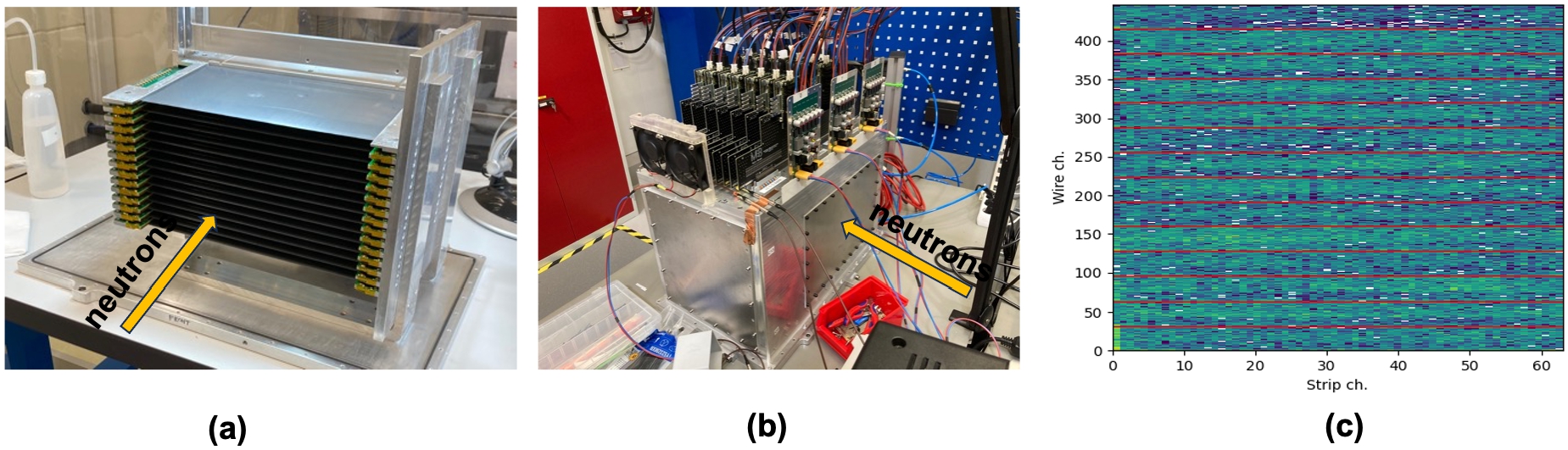
Although the active area of the Multi-Blade detector is relatively small compared to the technologies developed for spectroscopy and diffraction applications, the Multi-Blade detector is highly segmented. The submillimeter position resolution and high count rate capability can only be achieved by reading out independently a large number of electronic channels. For example, the FREIA detector, which will have an active area of 30 cm × 30 cm, will require around 3000 closely packed independent channels and high-density feedtroughs to collect the signals generated in the detector and deliver them to the backend circuitry. Thus, an ASIC-based readout solution will be used for all Multi-Blade detectors delivered to all 4 instruments (i.e., AMOR, Test beamline, FREIA and ESTA). The chip selected for use in the Multi-Blade readout is VMM3a. This is a 64-channel front-end ASIC developed by the ATLAS collaboration at CERN for the readout of the Micro-Pattern Gas Detectors in the context of the New Small Wheel Upgrade [21]. Its overall role is to amplify, shape, filter and convert the analog output from the detector into streams of digital data. The carrier board, called hybrid, hosts a pair of VMM3a chips, thus providing 128 input signals [59]. The test performed at PSI with the AMOR version of the Multi-Blade detector used a readout system consisting of 14 VMM3a hybrids for the readout of the 1344 individual signals from the wires and strips, see Figs 7(b) and (c) and Ref. [62].
4.2.The Multi-Grid detector for direct spectroscopy instruments
Multi-Grid is a detector concept developed at the Institut Laue-Langevin (ILL) [38,39] as the technical solution for direct spectroscopy applications, the instrument class heavily affected by the high cost of the 3He gas. The first Multi-Grid prototypes were jointly developed by the ILL and the ESS within the CRISP [18] and BrightnESS [10] EU-funded projects. This detector design makes use of a stack of grids mounted in a vessel filled with the Ar/CO2 gas mixture. The building blocks of the Multi-Grid detector are shown in Fig. 8. Each grid consists of a number of identical rectangular voxels with a typical size of 20 mm (width) × 20 mm (height) × 10 mm (depth). The elements of the grids crossed orthogonally by the incoming neutrons, called blades, are coated with a thin layer of the 10B4C converter, see Fig. 8 (a). The detector active area will be built by stacking several grids on top of each other with insulating spacers between them to form a column. Thin tungsten wires will be strung through the centers of all voxels in the stack and play the role of anodes, while the grids will function as the cathodes of a proportional gas counter.
The Multi-Grid design allows for an easy scale-up to cover the large solid angles in both horizontal and vertical scattering planes required by chopper spectrometers. The desired angular coverage in the vertical plane is determined by the detector height, which is given by the number of grids stacked in the column. One or more columns can be inserted into a detector vessel, which can then be replicated as many times as needed to cover the required angular coverage in the horizontal scattering plane. The process of assembling a detector column is shown in Fig. 9. The number of voxels in depth (typically between 15 and 20) and the thickness of the Boron layer coated on the orthogonal blades (typically ∼1 μm) can be optimized to provide a detection efficiency of >50% for 2.5 Å, which meets the efficiency requirements for most direct geometry instruments. The height and depth of the voxel of the grid determine the spatial and time resolution of the detector, respectively [4]. Multi-Grid operates with a continuous flow of the Ar/CO2 gas mixture.
Fig. 8.
(a) Top: The design principle and building blocks of the Multi-Grid detector. The photographs show coated blades ready to be cut into two parts and inserted into the grid structure. (b) Examples of assembled grids with different numbers of voxels per grid and voxels of different sizes developed over the years for testing purposes. See text for details.
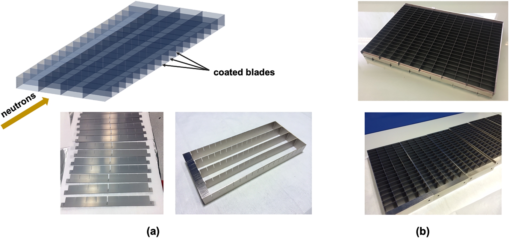
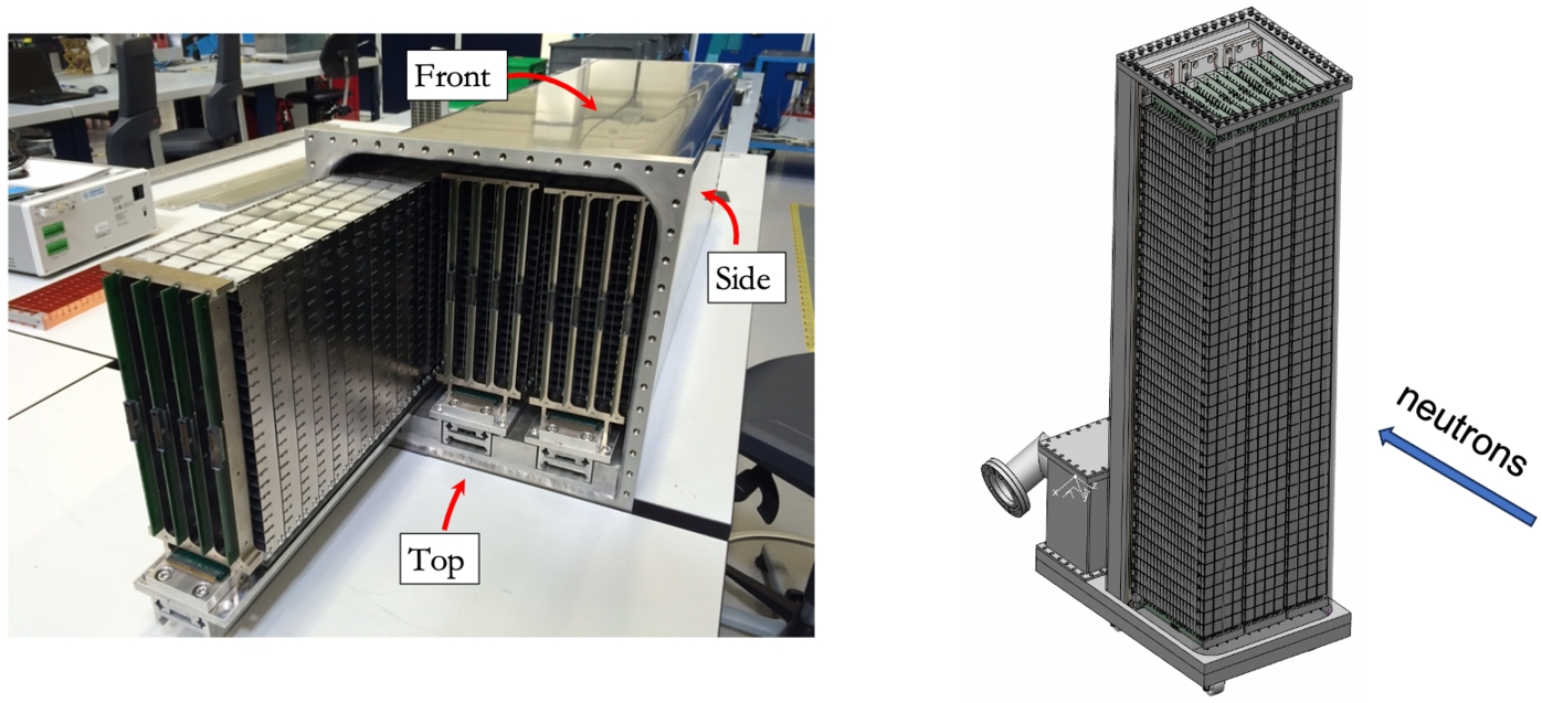
Fig. 9.
Left: Photograph taken during the operation of inserting the detector columns into the detector vessel. The next step in the manufacturing process is the mounting of the anode wires through each voxel of the grids and the connection of the electrodes to the readout circuitry. Right: Drawing of the detector assembly consisting of 3 columns of 40 grids each. The neutrons will hit the detector from the side marked as ‘front’ and interact with the coated blades generating signals that will be collected by both the anode wires and the cathode grids.
One of the most important requirements for detector technologies employed by the direct spectroscopy instrument class is the signal-to-noise ratio. Therefore special attention needs to be devoted to the design of the detector and associated shielding in order to minimize the gamma and neutron backgrounds and spurious reflections. The gamma background arises from the direct reaction of the environmental γ-rays with the detector materials and from those emitted in the nuclear reactions between the low- and high-energy neutrons with the inner structure surrounding the active area of the detector. The gamma-sensitivity of the Multi-Grid detector was investigated both with neutron beam and laboratory γ-sources [44]. The results of those tests showed that although the Boron-film-based detector technologies have a poorer intrinsic separation between the gamma- and neutron-generated signals compared to the 3He tubes, the proper selection of the discriminator threshold enables γ-sensitivities of 10-5 or lower in normal operation conditions, with acceptable loses in the neutron detection efficiency. The results obtained in Ref. [44] are representative of all multi-layer gas detectors based on the 10B4C solid-converter. Also, tests performed at ILL with the early Multi-Grid prototypes indicated a large background component arising from the natural contamination of the Aluminium material used in the grid structure with α-emitting impurities such as U and Th [9]. This problem was solved by using high-purity Aluminium as the substrate material for the blades produced for use in all future Multi-Grid technology demonstrators [3,7,8].
The initial instrument suite approved for construction at ESS contains two direct spectroscopy instruments, CSPEC and T-REX [5]. The two instruments are highly versatile and mutually complementary. CSPEC focuses on the cold regime and the corresponding broad scientific profile of low-energy excitations [22], while T-REX uses both the cold and thermal beams delivered by the moderator and has a scientific emphasis on magnetism [77]. For CSPEC, the secondary flight path is 3.5 m and the detector needs to cover the solid angle between 5° and 140° horizontally and ±26° in the vertical plane. This can be achieved with 32 modules (columns) with a height of 3.5 m. Each module is a stack of 140 grids each 15 cm wide (6 voxels) and 16 cm deep (16 voxels). A voxel size of 2.5 cm (width) × 2.5 cm (height) × 1 cm (depth) provides the required wavevector transfer [5,22]. The T-REX instrument has a secondary flightpath of 3 m. The detection system must cover the polar angular range from −25° to +15° and the azimuthal angular range from −36° to +144° [5,77]. This gives a total active area of 21 m2, which could be covered with 10 arc-shaped Multi-Grid modules, each consisting of 6 columns with a height of 2.2 m (110 grids).
Building such large gas detectors requires reliable and efficient mass production of all parts as well as proper shielding of the individual columns. For the mechanics, the requirements for angular coverage, wavevector transfer and efficiency translate into competing requirements on minimum space use, low material budget, high manufacturing precision and stable mechanical structures. A series of small-size Multi-Grid demonstrators were built in the past years at ESS in order to optimize the baseline designs for both CSPEC and T-REX detectors and enable a demonstration of the integration with active detector components and electronics. These prototypes were tested at different sources and instruments with mixed results [3,7,8]. The experimental data collected during the measurement with one of the Multi-Grid prototypes at the CNCS instrument at SNS [24,73] indicated that both the gamma and neutron detection efficiencies meet the instrument requirements and the rate capability is better than that of the conventional 3He-tubes due to the distribution of the peak count rate in depth over many voxels [3]. A photograph of the Multi-Grid prototype used in the CNCS test is shown in the left panel of Fig. 10. The detection efficiency measured relative to the efficiency of a 6-bar 3He-tube is displayed in the right panel of the same figure. A similar test was performed at the SEQUOIA chopper spectrometer at SNS [26]. Three Multi-Grid prototypes were installed in the SEQUOIA detector tank as shown in the left panel of Fig. 11 with the intention to test several design aspects related to the size of the grids and voxels, the substrate material used for coating, operation in vacuum and, most importantly, the performance of the Multi-Grid technology in the thermal and epithermal regime. Examples of scattering data collected with the SEQUOIA detectors and the three Multi-Grid prototypes are shown in the middle and right panels of Fig. 11.
Fig. 10.
Left: Photograph of the Multi-Grid prototype installed at the CNCS instrument at SNS. Right: Wavelength-dependent detection efficiency of the Multi-Grid detector obtained from the measurement at CNCS. The experimental values shown in the plot are relative to the calculated efficiency for a 6-bar 3He-tube. The theoretical efficiency curves for the Multi-Grid detector and the 6-bar 3He-tube are also shown. Adapted from ref. [3] ©2017 IOP Publishing Ltd and Sissa Medialab srl.
![Left: Photograph of the Multi-Grid prototype installed at the CNCS instrument at SNS. Right: Wavelength-dependent detection efficiency of the Multi-Grid detector obtained from the measurement at CNCS. The experimental values shown in the plot are relative to the calculated efficiency for a 6-bar 3He-tube. The theoretical efficiency curves for the Multi-Grid detector and the 6-bar 3He-tube are also shown. Adapted from ref. [3] ©2017 IOP Publishing Ltd and Sissa Medialab srl.](https://ip.ios.semcs.net:443/media/jnr/2024/26-2-3/jnr-26-2-3-jnr230012/jnr-26-jnr230012-g010.jpg)
Fig. 11.
Left: Photograph taken during the testing of the three Multi-Grid prototypes at the SEQUOIA instrument at SNS. Middle: Plot showing a 3D-histogram of neutron hit positions from white beam measurement on Si-powder. Note that the color scale for the 3He-tubes and the Multi-Grid detectors are different. Right: Comparison of the Multi-Grid (red) and 3He-tubes (blue) energy transfer data collected with a vanadium sample at 50 meV. The elastic peak is centered at ΔE = 0. The Multi-Grid data contains the events recorded by all three detectors.
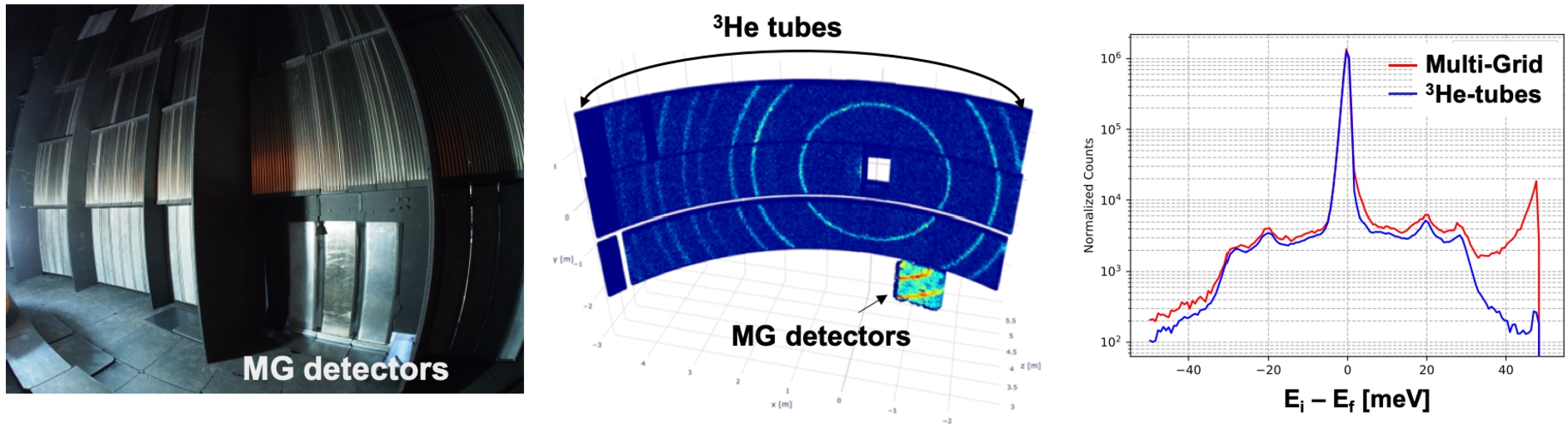
The results of both SNS tests indicated that the multiple detection layers in the Multi-Grid stacks enhance the scattering effects in the Aluminium material used as the substrate for the converter layer and in the grid structure, with negative effects for the signal-to-noise ratio. For neutron wavelengths above 1 Å, coherent scattering is the dominant component until approximately 4.7 Å, the Aluminium cut-off, where it drops under the time-independent background level [73,77]. The scattered signal adds a shoulder close to the tail of the main peak, see right panel of Fig. 11, which leads to a slight change of the line shape that affects the ability to extract the small quasi-elastic signals occurring in this region. In order to reduce the internal scattering of the neutrons, the coating with 10B4C of the radial blades of the grids was studied in GEANT4 simulations [23] and the model predictions were tested against the experimental results obtained with a Multi-Grid prototype exposed to the neutrons delivered by the V20 beamline at the BERII reactor at HZB [30,81]. The additional coating of the side blades was found to slightly improve the peak shape, but the results obtained were still not satisfactory [7]. The need for additional studies in order to alleviate the internal scattering effects as well as issues with the mass production of the Multi-Grid detectors affected the entire construction schedule of the CSPEC instrument. Therefore the instrument team decided to use the 3He-based detector technology instead. However, the Multi-Grid technology is still considered for use by the T-REX instrument, subject to further optimizations. T-REX is expected to enter commissioning in 2027 with 40% of the total required angular coverage for the detector. Specific details about the size of the detector vessel and grids and how challenges associated with the engineering design will be mitigated are currently being discussed and reviewed by both the instrument and detector teams. The lessons learned from the work performed for the CSPEC version of Multi-Grid will guide the design of the T-REX detector.
5.Boron-based detectors for the ESS instruments developed at partners sites
5.1.Boron-coated straw tubes for LoKi (SANS)
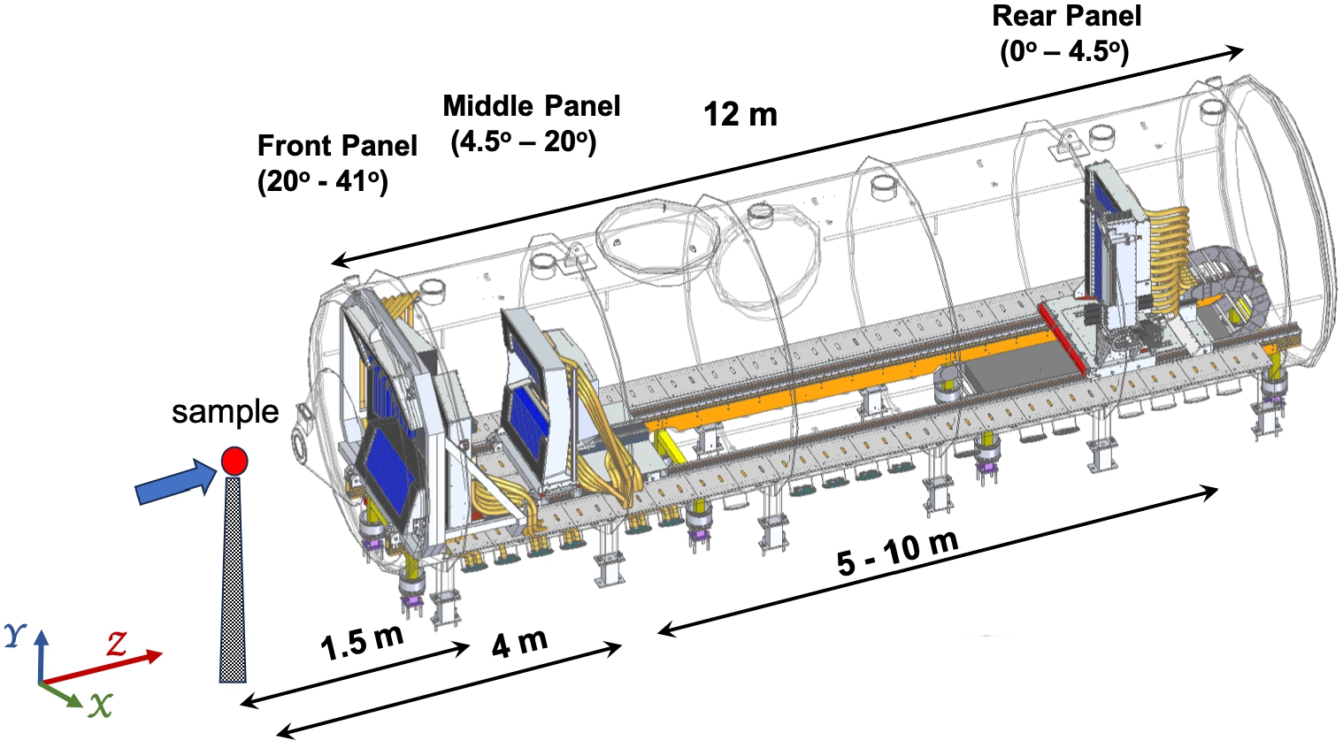
LoKI is one of the two SANS stations currently under construction at ESS [5]. The instrument is being developed in collaboration with Science and Technology Facilities Council (STFC) in the U.K. [40]. LoKi is designed to be a broad-band high-intensity instrument allowing the data to be collected simultaneously over 3 orders of magnitude in the Q range [28,41]. This will be achieved with the help of 3 detector panels located inside a 12 m long and 3.5 m diameter vacuum vessel as shown in Fig. 12. The Front and Middle detector panels will have fixed positions around 1.5 and 4 m away from the sample, respectively, while the Rear detector will ride on a track, allowing translation along the beam direction between 5 and 10 m from the sample position. The Front panel will cover scattering angles from 20° to 41°, the Middle panel will cover the angles from 4.5° to 20° and the Rear detector will detect the neutrons scattered between 0° and 4.5° [5,41].
Fig. 12.
Layout of the LoKi detector tank featuring the 3 detector panels. The direction of the incoming beam (along the Z-axis) is shown by the blue arrow.
It was clear from the time of submission of the LoKi proposal (2012) that such extensive angular coverage cannot be achieved with the 3He-based detectors, the conventional detector technology for SANS instruments. Moreover, the rate capability of the 3He tubes was deemed inadequate for the requirements of the ESS SANS instruments. A few detector designs were discussed in the years following the submission of the LoKi proposal, all based on the 10B-solid converter [2,42,43]. The current detector technology for the LoKi instrument was selected based on the assessment of the physics performance, cost and design challenges for all proposed designs.
Fig. 13.
(a) Photograph of Boron-coated straws, the building blocks of the LoKi detector systems. One tube consists of 7 closely packed straws coated on the inside with a thin layer of 10B4C [66]. (b) Cartoon showing the arrangement of tubes in a 2×4 array. The Loki detector module consists of 2 such arrays. The radial lines starting from the center of the tubes are the result of rendering in GEANT4, the software used to generate the cartoon. The modules are mounted in the detector frame such that the angle between the incoming neutrons, represented by black arrows, and the tubes is 20°. See text for details. (c) Photograph of two LoKi detector modules. (d) Comparison between the measured and calculated efficiency of the LoKi detectors. The measurement was performed at the LARMOR instrument at ISIS for the wavelength region of interest for LoKi.
![(a) Photograph of Boron-coated straws, the building blocks of the LoKi detector systems. One tube consists of 7 closely packed straws coated on the inside with a thin layer of 10B4C [66]. (b) Cartoon showing the arrangement of tubes in a 2×4 array. The Loki detector module consists of 2 such arrays. The radial lines starting from the center of the tubes are the result of rendering in GEANT4, the software used to generate the cartoon. The modules are mounted in the detector frame such that the angle between the incoming neutrons, represented by black arrows, and the tubes is 20°. See text for details. (c) Photograph of two LoKi detector modules. (d) Comparison between the measured and calculated efficiency of the LoKi detectors. The measurement was performed at the LARMOR instrument at ISIS for the wavelength region of interest for LoKi.](https://ip.ios.semcs.net:443/media/jnr/2024/26-2-3/jnr-26-2-3-jnr230012/jnr-26-jnr230012-g013.jpg)
The LoKi detection system uses the boron straw proportional wire tube technology developed by Proportional Technology, Inc. (PTI) [66] for homeland security and neutron scattering applications [47–49]. The basic detection unit is an array of 7 resistive wire tubes referred to as “straws” enclosed in a hollowed 1-inch Aluminium cylinder as shown in Fig. 13(a). Each straw has 7.5 mm diameter and it is made of thin copper foil coated with ∼1 μm thin layer of 10B4C. The Aluminium host tube is sealed and operates with 0.7 atm of the Ar/CO2 (90–10 by volume) gas mixture. The tubes must operate in a vacuum vessel, therefore the ISIS detector design team assembled them in a
Fig. 14.
Left: The principle of multiplexing used for the LoKi detectors. The position along the straws and the straw ID can be reconstructed by using the amplitudes of the signals collected at the 4 ends of the circuit. Right: Experimental response of a tube with 7 straws represented as position along the straws with 2 mm/bin as a function of the straw ID. The equations used to reconstruct the position are those given in the left panel of the figure.
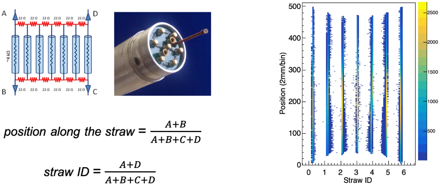
The entire LoKi detection system will consist of 56 (modules) x 16 (tubes) x 7 (straws) independent gas counters. Reading out the signals from both ends of the straws individually would make this detector technology very expensive and unattractive for most applications. In order to alleviate the cost issue, the ISIS electronics team designed multiplexer boards that are attached to the ends of each 7-straw tube. These boards will connect the wires of all straws using resistances and thus create a 4-end resistive chain, see left panel of Fig. 14. Each end of the chain is connected to a preamplifier that records a signal proportional to the length of the chain from the formation point (neutron detection point). Considering a 7-straw tube in the vertical position, the center of gravity along the X-axis is used to identify in which straw a neutron was absorbed and the one along the Y-axis is used to calculate where a neutron interacts along the length of the straw, see equations included in Fig. 14. This arrangement has the capability of reducing the number of readouts per tube from 14 down to 4. The preamplified signals are processed with the help of the 32-channel CAEN ADC R5560 open-FPGA digitizers with a sampling rate of 125 MHz [14]. 3584 ADCs channels will be used to read out the entire instrument. A constant position resolution of ∼7 mm along the tube was measured for neutron rates of up to 4 · 105 Hz per tube [67], which meets the requirements of the LoKi instrument [5].
The LoKi detector modules were intensively tested at ISIS during the R&D and production phases as well as in GEANT4 simulations [46]. The data reduction and analysis, including the position calibration of the straw tubes, is expected to be more complex than for the 3He-based technologies currently employed on time-of-flight SANS instruments due to the larger number of detection elements arranged in a volume [17]. In 2022 eight LoKi detector modules were tested on the LARMOR instrument at the ISIS facility [25] with the full data acquisition pipeline [80]. At the time of writing this paper the installation of the LoKi beamline components is ongoing. The detector frames for the 3 detector panels will soon be installed inside the vacuum vessel. 36 out of the 56 detector modules that arrived at ESS are currently undergoing incoming acceptance tests with a neutron source in the ESS detector laboratory located at Lund University [55]. The purpose of these tests is to ensure that the detectors arrived safely at ESS from UK, all channels are operational and meet the operational specifications in terms of high-voltage behavior and signal reconstruction. A photograph of the experimental setup used for the testing of the LoKi detector modules and results from the test are shown in Fig. 15.
5.2.The JALOUSIE-type detectors for powder and single-crystal diffraction
The initial diffraction suite at the ESS comprises two powder diffractometers DREAM [5,72] and HEIMDAL [5,34], and the single-crystal diffractometer MAGiC [5,51]. A common feature of these three diffractometers is the detector technology based on 10B-coated layers in inclined geometry used to detect the scattered neutrons. The detectors are designed by the CDT company located in Heidelberg, Germany [16] and are known as JALOUSIE-detectors [31].
Fig. 15.
Left: Photograph of 4 LoKi detector modules undergoing incoming acceptance tests in the ESS detector laboratory at Lund University. The neutron source (AmBe) is placed in the center of the table. Right: 2D spectrum collected with one detector submodule showing the number of counts per straw as a function of position given in units of 2 mm/bin.
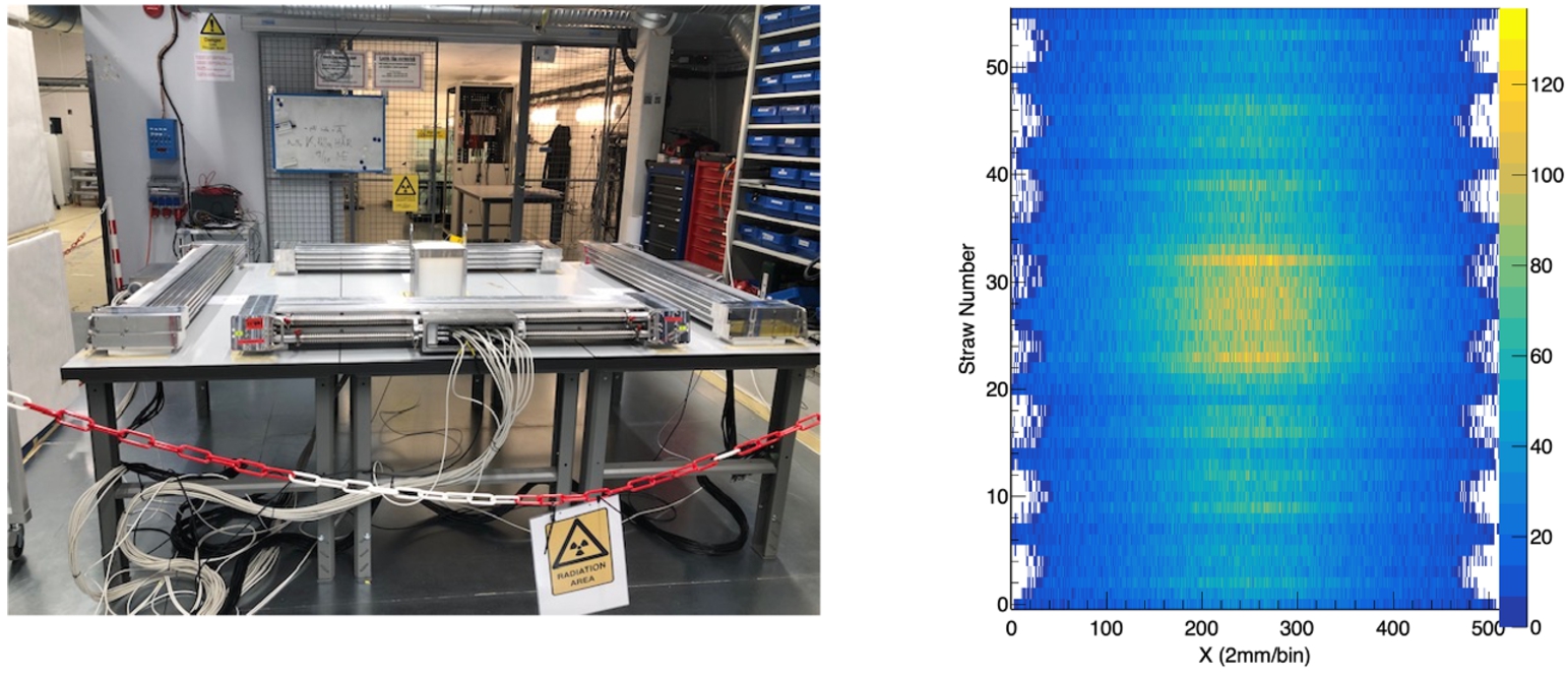
Fig. 16.
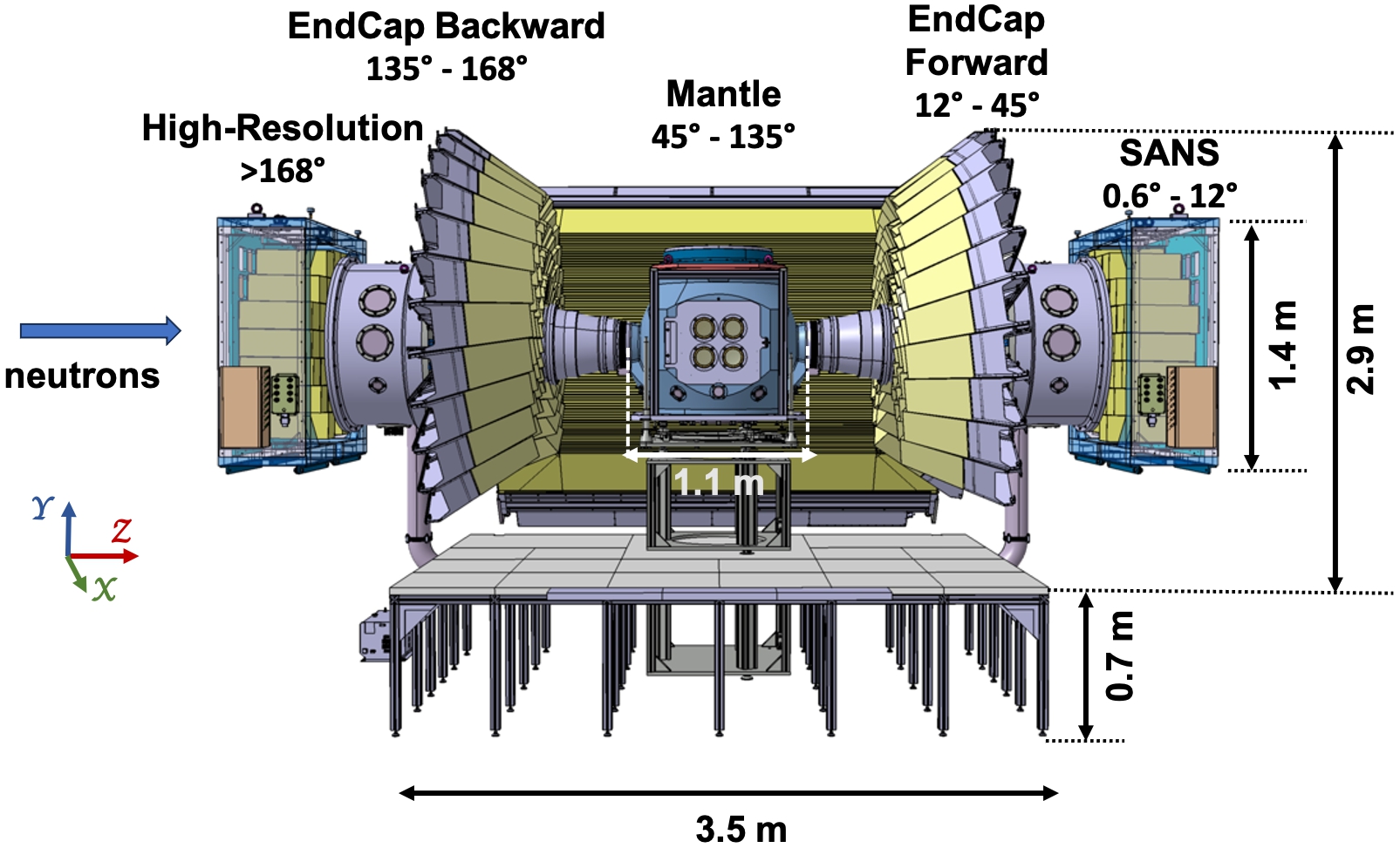
Layout of the DREAM sample scattering system showing the sample vessel and the detectors. The angle covered by each detector is marked on the figure. The distance between the sample position and the entrance windows of the Mantle segments and the SUMO sectors in both Forward and Backward EndCap detectors is 1.1 m and the distance between the sample and the entrance windows of the cuboids in the High-Resolution detector is ∼2.5 m. The incoming beam direction is shown by the blue arrow. The drawing shows the angular coverage in full scope. Approximately 40% of the system will be available at the hot commissioning of the source, see text for details.
DREAM (Diffraction Resolved by Energy and Angle Measurements) is the first instrument in its class planned to enter the commissioning phase in 2024. It is designed to make scientific contributions to the field of magnetism and materials with complex structures and relatively large unit cells [5,72]. DREAM is a new type of time-of-flight powder diffractometer that will use several counter-rotating disc choppers to enable the selection of symmetric pulse shapes with time resolutions from the 10 microsecond to millisecond range. The instrument will be 75 m long and it will use both the thermal and cold moderators to operate with two wavelength frames,
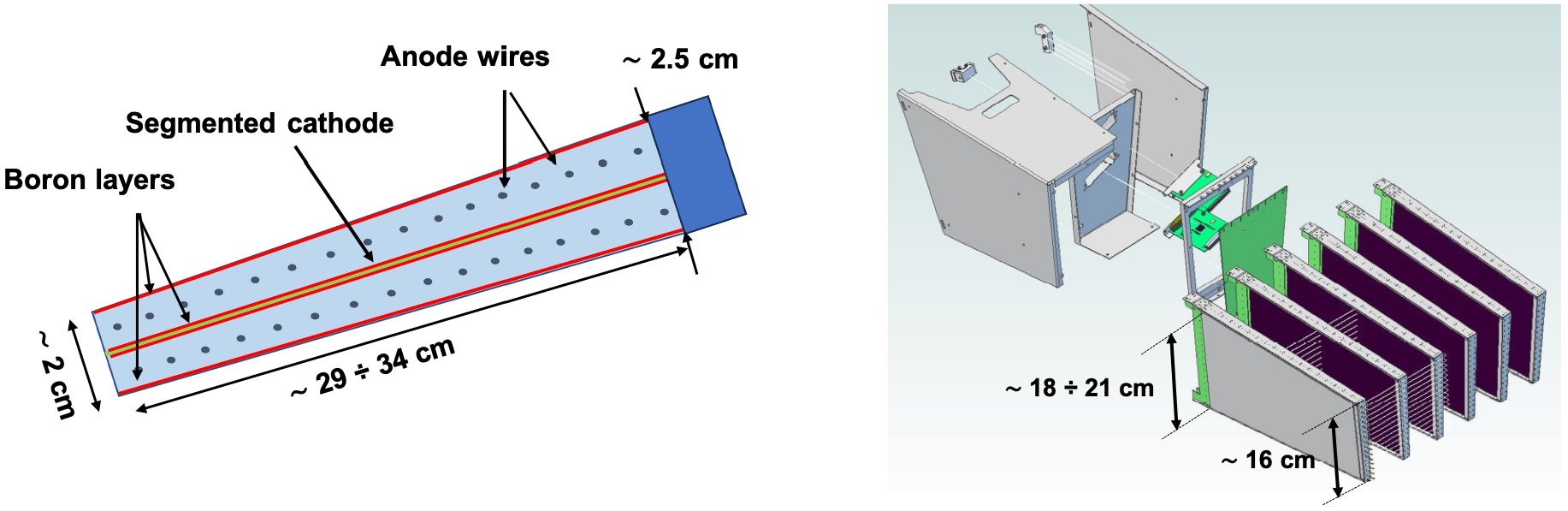
The basic JALOUSIE detector unit is a thin trapezoidal gas counter called segment which comprises two independent multi-wire proportional counters sharing a common segmented cathode. A cartoon of the generic JALOUSIE detector segment is shown in the left panel of Fig. 17. The segment has a tapered shape (i.e., the distance between the wire grid and the segmented cathode is gradually increasing with depth) in order to ensure close packing with minimal dead zones between the neighboring segments when assembled in cylindrical geometry around the sample. The Boron converter is applied on the inner sides of the segment housing and/or on both sides of the segmented cathode. To facilitate the installation work, maintenance and testing, the JALOUSIE detectors are designed to be modular, and this is achieved by assembling a number of detector segments in mounting units that can operate independently. An example of a mounting unit built to operate in the EndCap detector is shown in the right panel of Fig. 17.
The electrode structure of a JALOUSIE segment can be easily adapted to fulfill the requirements for position resolution, which for DREAM are ∼6 mm (FHWM) in 2θ and ∼10 mm (FWHM) in ϕ. Detection efficiencies greater than 50% at 1 Å can be achieved by designing the detector to allow the incoming neutron to have 10 nominal interactions with the Boron layers. If both the segment housing and the cathode are coated with Boron, 10–12 nominal interactions require detector depths of up to 35 cm. Higher efficiencies are possible by increasing the number of Boron layers in the beam path, which requires an increase in the segment depth. When only one Boron layer is used per detector segment, a minimum sensitive depth of 520 mm is needed to achieve 50% efficiency for thermal neutrons. This will be the case for the HEIMDAL JALOUSIE-detector described in Ref. [76] and the MAGiC detector, both aiming for a position resolution better than 2 mm in the horizontal plane.
Fig. 17.
Left: cartoon showing the design principle of a generic JALOUSIE detector segment (top view). Right: the schematic of the process of assembling an EndCap SUMO detector module in a single mounting unit that can operate independently. The dimensions given in both figures are generic for the EndCap SUMO segments and indicate the approximate size of the active area.
The arrangement of the five detectors (named EndCap Forward, Mantle, EndCap Backward, High-Resolution and SANS) around the sample vessel as shown in Fig. 16 was chosen to enable the highest possible angular acceptance and performance in terms of spatial resolution, efficiency, and count rate capability, but also allow for staged installation and easy access to the sample position. The drawings for each detector type are shown in Fig. 19. The EndCap Forward/Backward detectors and the High-Resolution/SANS detectors are made of identical and interchangeable detection units. The EndCap detectors consist of 12° sectors (in ϕ) arranged concentrically around the vacuum tube connecting the beam guide with the sample vessel. Each sector consists of 4 independent units called SUMOs (SUper MOdules) designed to be stacked on top of each other such that the detection efficiency is uniform across and along the sector, see Figs 19(a) and (b). This requirement is valid for all detector modules used to build the DREAM detector system. The High-Resolution and SANS detectors are made of 33 and 36 identical and interchangeable modules, respectively, called cuboids. The drawing of the High-Resolution detector is shown in Fig. 19(c). The Mantle detector, depicted in Fig. 19(d), is made of long trapezoidal segments with the size of the active area closest to the sample measuring 2.2 m (external dimension is 2.5 m). The segments are assembled in mounting units of 6, shaped to fit seamlessly between the two EndCap detectors and provide homogeneous coverage with minimal gaps and little variation in the physics performance in the transition zones.
While all the DREAM detectors are based on the same technology, their internal electrode structure is different. The EndCap and High-Resolution (SANS) detectors are made of segments consisting of cathodes with equal strip sizes. The segments are arranged in modules that are mounted in the detector frame such that the wires are parallel to the beam axis and the strips are perpendicular to it. Same as the EndCap detector segments, the cuboids of High-Resolution/SANS detectors consist of strips of equal size oriented perpendicular to the beam axis and wires facing the sample. Each cuboid is inclined by 1° in both cartesian directions with respect to the incoming neutron axis in order to avoid non-sensitive blind-see-through areas. The Mantle segment is made of 256 cathode strips designed to point concentrically to the sample and deliver a constant resolution of
In all detectors, the position of the detected neutron is given by the coincidence of the signals recorded in the anode wires with the signals collected by the cathode strips. This readout scheme and the tapered shape of the detector segments give rise to a grid of 3D sensitive cells (voxels) with hexahedron-like shapes and sizes (volumes) that increase with increasing distance from the sample. For example, the volume of a Mantle detector voxel located around 90° scattering angle and close to the entrance window is around 6.6 mm (width) × 10.5 mm (height) × 11.4 mm (depth) and becomes (approx.) 13 mm × 12 mm × 11.4 mm at the far ends [16]. Worthwhile to mention here that the detector is designed to allow higher voltages to be applied to the far wires in order to improve the homogeneity of the detector response. The DREAM detector system will consist of ∼106 detector voxels during initial operations, see Table 2. This number will increase by at least a factor of two in full scope when the angular coverage of the detector is expected to increase from 2 sr to 5.1 sr. All detectors are designed and wired to collect data simultaneously. The timestamped data packets will be streamed to the Data Management and Software Centre (DMSC) for data reduction and analysis [17,20].
Table 2
Main design parameters for the DREAM detectors. The third column gives the number of detector modules planned to operate during Phase 1 of commissioning the ESS neutron source. The number of detector voxels per module given in the last column is the product of the number of segments in the module (column 4), number of counters per segment (2), number of wires (column 5) and number of strips per segment (column 6)
| Detector system | Module name | Number of modules initial operations | Number of segments per module | Number of wires per segment | Number of strips per segment | Number of voxels per module |
| SANS | Cuboid | 36 | 8 | 16 | 32 | 8192 |
| Forward | SUMO3 | 5 | 4 | 16 | 16 | 2048 |
| SUMO4 | 5 | 6 | 16 | 16 | 3072 | |
| SUMO5 | 5 | 8 | 16 | 16 | 4096 | |
| SUMO6 | 5 | 10 | 16 | 16 | 5120 | |
| Mantle | Mounting unit | 5 | 6 | 32 | 256 | 98304 |
| Backward | SUMO3 | 11 | 4 | 16 | 16 | 2048 |
| SUMO4 | 11 | 6 | 16 | 16 | 3072 | |
| SUMO5 | 11 | 8 | 16 | 16 | 4096 | |
| SUMO6 | 11 | 10 | 16 | 16 | 5120 | |
| High-resolution | Cuboid | 33 | 8 | 16 | 32 | 8192 |
The DREAM detector system is very similar to the detectors designed and delivered for operation in the high-intensity time-of-flight neutron diffractometer POWTEX for powder and texture analysis approved for construction as part of the instrument suite for the (new) eastern guide hall at the FRM2 research reactor in Garching [36,65,68]. The design and construction of the detectors for DREAM benefited from the extensive R&D phase and experience gained during the manufacturing and testing of the POWTEX detectors. The first JALOUSIE detector prototype was tested in 2014 at the TRIGA reactor in Mainz with results that provided a position resolution of
Fig. 18.
Evaluation of the detection efficiency of a pair of Jalousie detector segments (2 segments, 4 wire planes, 8 Boron layers) performed with a neutron beam of 1.17 Å delivered by the HEiDi diffractometer at FRM2. The thickness of each Boron layer was 1.2 μm. Left: Photograph of the experimental setup. The direction of the incident beam is shown by the red arrow. The assembly was mounted on a mobile arm which allowed the variation of the incidence angle of the beam with respect to the detector surface. Right: Measured count-rate as a function of the inclination angle of the segments with respect to the beam axis. The experimental countrates for each wire plane were fitted with the theoretical curves which yielded a detection efficiency of ∼47 % for the 3 wire planes (6 Boron layers). See text for further details.
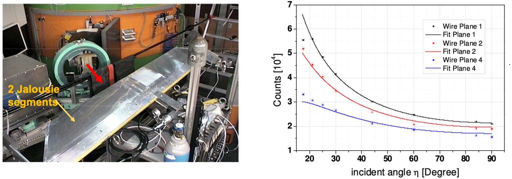
Fig. 19.
Drawings of the JALOUSIE detectors for DREAM. The external dimensions of the detectors are marked on the figures. a) The 12° EndCap sector. b) Front view of the EndCap detector (Forward or Backward) consisting of several 12°-sectors. (c) The High-Resolution detector consisting of 33 cuboids. d) The Mantle detector. Highlighted in light green is one mounting unit.
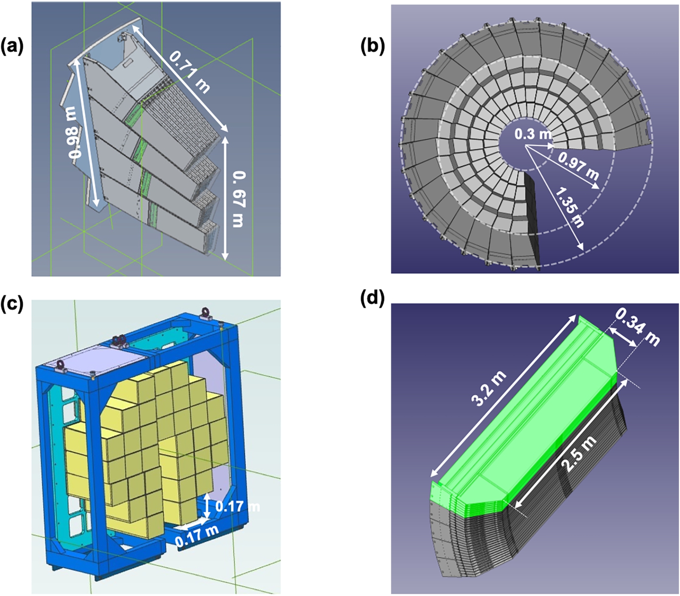
Fig. 20.
Top left: Photograph of the DREAM EndCap 12° sector during the detector test at BERII reactor. The sector was placed at 1.1 m from the sample and covered the scattering angles between 137.5° and 168°. Top center: drawing of the GEANT4 model of the DREAM EndCap sector. Top left: X-Y representation of the voxel centers calculated in GEANT by placing the virtual model of the EndCap sector in the same position as the real detector during the test at the V20 beamline.
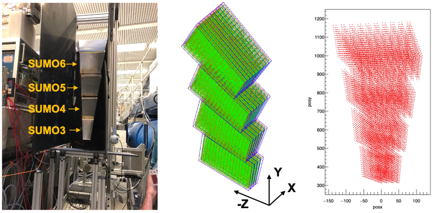
Fig. 21.
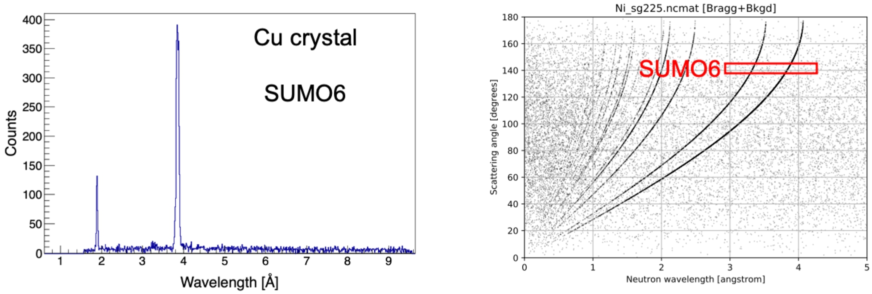
Left: Experimental spectrum obtained from the measurement with the Cu crystal sample with the SUMO6 module of EndCap. The SUMO6 module covered the 2θ angles between 137.5° and 145°. The conversion of the TOF data to the wavelength space was made by using the coordinates of the centers of the detector voxels obtained in the GEANT4 simulation of the detector module. The two Bragg peaks visible in the spectrum are located at 1.89 and 3.85 Å. Right: Scattering angle versus wavelength calculated for the Cu crystal with the NCrystal software package. The scattering angles covered by SUMO6 are marked by the red square.
The first EndCap sector designed and built for DREAM was tested at the V20 beamline at the BERII reactor at HZB [30] shortly before the reactor shutdown in December 2019. The V20 beamline was operated in both normal and wavelength-frame-multiplication (WFM) mode during the test. In the WFM mode, the expected wavelength resolution is 1.8 % for a flight path of 23.8 m [81]. The sector was placed at 1.1 m with respect to the sample and covered scattering angles between 137.5° and 168°. The measurement aimed to test the functionality of the detector and provided several sets of data collected with various reference samples such as Ni power, Cu crystal, and vanadium. These were used to define the most efficient ways to implement the channel mapping of the neutron events, which implies the conversion from ASIC channel ID (and timestamp) to voxel ID and TOF information. In order to be able to convert the data from the TOF to λ- and Q-space and extract the physics observable relevant to power diffraction, each voxel must have well-defined position coordinates (x, y, z) with respect to the sample position. As shown in the treatment of the POWTEX data collected during the measurement at the POWGEN instrument [35], this step is not trivial for the JALOUSIE detectors. The hexahedron-like shapes of the voxels impose additional challenges on the position determination and calibration of these detectors, which rely heavily on analytical calculations by using information from CAD drawings and/or computer simulations.
Figure 20 shows a photograph of the EndCap sector during the test at the BERII reactor and the equivalent GEANT4 model of the sector used to convert the data from TOF- to λ-space. An example of a diffraction spectrum obtained with the SUMO6 module of EndCap and the Cu crystal sample is shown in the left panel of Fig. 21. SUMO6 is the largest of the 4 detector modules of the EndCap sector and it covered the scattering angles between 137.5° and 145°. The positions of the detector voxels used in the analysis were calculated by using the voxel shapes and positions resulting from the simulation of the experimental arrangement in GEANT4 and placing the virtual copy of the EndCap detector in the same location with respect to the sample as the real EndCap detector was placed in the V20 beamline. Two Bragg peaks located at 1.89 and 3.854 Å are visible in the spectrum, in agreement with the predictions of the NCrystal library for thermal neutron transport [15] displayed in the right panel of Fig. 21.
The manufacturing by CDT of the DREAM detectors is ongoing. The EndCap SUMO modules will be delivered to ESS before the end of 2023. They will be followed in the first quarter of 2024 by the 5 Mantle mounting units and the 33 cuboids for the High-Resolution detector. All detectors will undergo a site inspection test at arrival, consisting of functionality measurements with a neutron source at the Lund Testing Facility [55]. In-situ commissioning with cosmic rays will take place as soon as the final services (power, gas, network) have been connected to the detectors.
6.Conclusions
The scientific performance of the ESS instrument suite relies heavily on new design concepts and instrumentation, especially detectors. The core technology is represented by the 10B-film-based proportional counters developed as alternatives to the 3He-based detectors. Three of the instruments planned to enter the cold commissioning phase in the second half of 2024, namely LoKi (SANS), the Test beamline, and the powder diffractometer DREAM, will operate with 10B-based detectors designed and built in-house or by external partners. The two reflectometers FREIA and ESTIA, the engineering diffractometer BEER and possibly the thermal chopper spectrometer T-Rex will also be instrumented with 10B-film-based gas counters. These detectors are the end product of about 10 years of development and testing of several generations of prototypes and demonstrators, all of which have brought major advances in the understanding of the technology as well as expertise in designing and building mechanically complex structures with high precision and reliability. Each of the instruments that will employ the 10B-film-based technology faces different requirements in terms of detector active area and spatial resolution, but they all converge for the count rate capability, detection efficiency and signal-to-background ratio. Optimism surrounds the potential of the 10B-film-based detector technology to succeed in providing high count rate capability, an area where the current state-of-the-art detectors are seriously challenged. However, the practical operation of 10B-film based detectors remains a complex venture due to the large number of readout channels and the complexity of the data reduction and calibration methods. Close cooperation with industrial and in-kind partners is essential all along from the design phase to the delivery of the detectors and continuing into the early days of operation and up to the full instrument and source design specifications.
Acknowledgements
A portion of this research used resources at the Spallation Neutron Source, a DOE Office of Science User Facility operated by the Oak Ridge National Lab. The support of the CNCS and SEQUOIA instrument teams, including G. Ehlers, M. Stone, A. Kolesnikov and V. Fanelli, is gratefully acknowledged.
References
[1] | S. Agostinelli, J. Allison, K. Amako, J. Apostolakis, H. Araujo, P. Arce, M. Asai, D. Axen, S. Banerjee, G. Barrand, F. Behner, L. Bellagamba, J. Boudreau, L. Broglia, A. Brunengo, H. Burkhardt, S. Chauvie, J. Chuma, R. Chytracek, G. Cooperman, G. Cosmo, P. Degtyarenko, A. Dell’Acqua, G. Depaola, D. Dietrich, R. Enami, A. Feliciello, C. Ferguson, H. Fesefeldt, G. Folger, F. Foppiano, A. Forti, S. Garelli, S. Giani, R. Giannitrapani, D. Gibin, J.J. Gómez Cadenas, I. González, G. Gracia Abril, G. Greeniaus, W. Greiner, V. Grichine, A. Grossheim, S. Guatelli, P. Gumplinger, R. Hamatsu, K. Hashimoto, H. Hasui, A. Heikkinen, A. Howard, V. Ivanchenko, A. Johnson, F.W. Jones, J. Kallenbach, N. Kanaya, M. Kawabata, Y. Kawabata, M. Kawaguti, S. Kelner, P. Kent, A. Kimura, T. Kodama, R. Kokoulin, M. Kossov, H. Kurashige, E. Lamanna, T. Lampén, V. Lara, V. Lefebure, F. Lei, M. Liendl, W. Lockman, F. Longo, S. Magni, M. Maire, E. Medernach, K. Minamimoto, P. Mora de Freitas, Y. Morita, K. Murakami, M. Nagamatu, R. Nartallo, P. Nieminen, T. Nishimura, K. Ohtsubo, M. Okamura, S. O’Neale, Y. Oohata, K. Paech, J. Perl, A. Pfeiffer, M.G. Pia, F. Ranjard, A. Rybin, S. Sadilov, E. Di Salvo, G. Santin, T. Sasaki, N. Savvas, Y. Sawada, S. Scherer, S. Sei, V. Sirotenko, D. Smith, N. Starkov, H. Stoecker, J. Sulkimo, M. Takahata, S. Tanaka, E. Tcherniaev, E. Safai Tehrani, M. Tropeano, P. Truscott, H. Uno, L. Urban, P. Urban, M. Verderi, A. Walkden, W. Wander, H. Weber, J.P. Wellisch, T. Wenaus, D.C. Williams, D. Wright, T. Yamada, H. Yoshida and D. Zschiesche, eds, GEANT4 – a simulation toolkit, Nuclear Instruments and Methods in Physics Research Section A 506: (3) ((2003) ), 250. doi:10.1016/S0168-9002(03)01368-8. |
[2] | G. Albani, E. Perelli Cippo, G. Croci, A. Muraro, R. Hall-Wilton, C. Höglund, A. Menelle, G. Grosso, F. Murtas, M. Rebai, L. Robinson, S. Schmidt, P.O. Svensson, M. Tardocchi and G. Gorini, High-rate measurements of the novel BAND-GEM technology for thermal neutron detection at spallation sources, Nuclear Instruments and Methods in Physics Research Section A 957: ((2020) ), 163389. doi:10.1016/j.nima.2020.163389. |
[3] | M. Anastasopoulos, R. Bebb, K. Berry, J. Birch, T. Bryś, J.-C. Buffet, J.-F. Clergeau, P.P. Deen, G. Ehlers, P. van Esch, S.M. Everett, B. Guerard, R. Hall-Wilton, K. Herwig, L. Hultman, C. Höglund, I. Iruretagoiena, F. Issa, J. Jensen, A. Khaplanov, O. Kirstein, I. Lopez Higuera, F. Piscitelli, L. Robinson, S. Schmidt and I. Stefanescu, Multi-Grid detector for neutron spectroscopy: Results obtained on time-of-flight spectrometer CNCS, Journal of Instrumentation 12: ((2017) ), P04030. doi:10.1088/1748-0221/12/04/P04030. |
[4] | K. Andersen, T. Bigault, J. Birch, J.C. Buffet, J. Correa, R. Hall-Wilton, L. Hultman, C. Höglund, B. Guérard, J. Jensen, A. Khaplanov, O. Kirstein, F. Piscitelli, P. Van Esch and C. Vettier, 10B Multi-Grid proportional gas counters for large area thermal neutron detectors, Nuclear Instruments and Methods in Physics Research Section A 720: ((2013) ), 116. doi:10.1016/j.nima.2012.12.021. |
[5] | K.H. Anderson et al., The instrument suite of the European spallation source, Nuclear Instruments and Methods in Physics Research Section A 957: ((2020) ), 163402. doi:10.1016/j.nima.2020.163402. |
[6] | O. Arnold, J.C. Bilheux, J.M. Borreguero, A. Buts, S.I. Campbell, L. Chapon, M. Doucet, N. Draper, R. Ferraz Leal, M.A. Gigg, V.E. Lynch, A. Markvardsen, D.J. Mikkelson, R.L. Mikkelson, R. Miller, K. Palmen, P. Parker, G. Passos, T.G. Perring, P.F. Peterson, S. Ren, M.A. Reuter, A.T. Savici, J.W. Taylor, R.J. Taylor, R. Tolchenov, W. Zhou and J. Zikovsky, Mantid – data analysis and visualization package for neutron scattering and μSR experiments, Nuclear Instruments and Methods in Physics Research Section A 764: ((2014) ), 156. doi:10.1016/j.nima.2014.07.029. |
[7] | A. Backis, A. Khaplanov, R. Al Jebali, R. Ammer, I. Apostolidis, J. Birch, C.C. Lai, P.P. Deen, M. Etxegarai, N. de Ruette, J. Freita Ramos, D.F. Förster, E. Haettner, R. Hall-Wilton, D. Hamilton, C. Höglund, P.M. Kadletz, K. Kanaki, E. Karnickis, O. Kirstein, S. Kolya, Z. Kraujalyte, A. Laloni, K. Livingston, O. Löhman, V. Maulerova, N. Mauritzon, F. Müller, I. Lopez Higuera, T. Richter, L. Robinson, R. Roth, M. Shetty, J. Taylor, R. Woracek and W. Xiong, Time- and energy-resolved effects in the Boron-10 based Multi-Grid and Helium-3 based thermal neutron detectors, Measurement Science and Technology 32: ((2021) ), 035903. doi:10.1088/1361-6501/abc63e. |
[8] | J. Birch, J.-C. Buffet, J.-F. Clergeau, J. Correa, P. van Esch, M. Ferraton, B. Guerard, J. Halbwachs, R. Hall-Wilton, L. Hultman, C. Höglund, A. Khaplanov, M. Koza, F. Piscitelli and M. Zbiri, In-beam test of the Boron-10 Multi-Grid neutron detector at the IN6 time-of-flight spectrometer at the ILL, Journal of Physics: Conference Series 528: , 012040. doi:10.1088/1742-6596/528/1/012040. |
[9] | J. Birch, J.-C. Buffet, J.-F. Clergeau, P. van Esch, M. Ferraton, B. Guerard, R. Hall-Wilton, L. Hultman, C. Höglund, J. Jensen, A. Khaplanov and F. Piscitelli, Investigation of background in large-area neutron detectors due to alpha emission from impurities in Aluminium, Journal of Instrumentation 10: ((2015) ), P10019. doi:10.1088/1748-0221/10/10/P10019. |
[10] | BrightnESS, URL https://brightness.esss.se/. |
[11] | R. Bruchhaus, R. Georgii, G. Kemmerling, J. Krüger, J. Wuttke and K. Zeitelhack, Stability and radiation test with a POWTEX JALOUSIE detector, FRMII – MLZ Anual Report 2017. URL https://www.frm2.tum.de/fileadmin/w00bnv/www/Aktuelles___Medien/Broschueren/Jahresberichte/JB_2017_online.pdf. |
[12] | J.C. Buffet, J.F. Clergeau, R.G. Cooper, J. Darpentigny, A. De Laulany, C. Fermon, S. Fetal, F. Fraga, B. Guérard, R. Kampmann, A. Kastenmueller, G.J. Mc Intyre, G. Manzin, F. Meilleur, F. Millier, N. Rhodes, L. Rosta, E. Schooneveld, G.C. Smith, H. Takahashi and K. Zeitelhack, Advances in detectors for single crystal neutron diffraction, Nuclear Instruments and Methods in Physics Research Section A 554: ((2005) ), 392. doi:10.1016/j.nima.2005.08.018. |
[13] | M. Bybjerg Brock, C.-C. Lai, A.B. Abrahamsen, L. Robinson, K. Kanaki, R. Hall-Wilton, A.C. Wulff and L. Theil Kuhn, Strain effects of absorbing layer on superconducting properties of a high-flux neutron detector, IEEE Transactions on Applied Superconductivity 32: (4) ((2022) ), 1800404. doi:10.1109/TASC.2022.3145322. |
[14] | CAEN 5560 Digitizer family, URL https://www.caen.it/subfamilies/55xx-digitizer-family/. |
[15] | X.-X. Cai and T. Kittelmann, NCrystal: A library for thermal neutron transport, Computer Physics Communications 246: ((2020) ), 106851. doi:10.1016/j.cpc.2019.07.015. |
[16] | CASCADE Detector Technologies, URL https://n-cdt.com/. |
[17] | M.J. Christensen, M. Shetty, J. Nilsson, A. Mukai, R. Al Jebali, A. Khaplanov, M. Lupberger, F. Messi, D. Pfeiffer, F. Piscitelli, T. Blum, C. Søgaard, S. Skelboe, R. Hall-Wilton and T. Richter, Software-based data acquisition and processing for neutron detectors at European Spallation Source – early experience from four detector designs, Journal of Instrumentation 13: ((2018) ), T11002. doi:10.1088/1748-0221/13/11/T11002. |
[18] | CRISP – Cluster of Research Infrastructures for Synergies in Physics, URL https://cordis.europa.eu/project/id/283745. |
[19] | R. Cubitt, H.M. Shimizu, K. Ikeda and N. Torikai, Refraction as a means of encoding wavelength for neutron reflectometry, Nuclear Instruments and Methods in Physics Research Section A 558: ((2005) ), 547. doi:10.1016/j.nima.2005.12.045. |
[20] | Data Management and Sotware Centre, URL https://europeanspallationsource.se/data-management-software-centre. |
[21] | G. de Geronimo, G. Iakovidis, S. Martoiu and V. Polychronakos, The VMM3a ASIC, IEEE Transactions on Nuclear Science 69: ((2022) ), 966. doi:10.1109/TNS.2022.3155818. |
[22] | P.P. Deen, S. Longeville, W. Lohstroh, F. Moreira, G. Fabrèges, L. Loaiza and D. Noferini, CSPEC: The cold chopper spectrometer of the ESS, a detailed overview prior to commissioning, Review of Scientific Instruments 92: ((2021) ), 105104. doi:10.1063/5.0059907. |
[23] | E. Dian, K. Kanaki, A. Khaplanov, T. Kittelmann, P. Zagyvaia and R. Hall-Wilton, Suppression of intrinsic neutron background in the Multi-Grid detector, Journal of Instrumentation 15: ((2019) ), P01021. doi:10.1088/1748-0221/14/01/P01021. |
[24] | G. Ehlers, A.A. Podlesnyak, J.L. Niedziela, E.B. Iverson and P.E. Sokol, The new cold neutron chopper spectrometer at the spallation neutron source: Design and performance, Review of Scientific Instruments 82: ((2011) ), 085108. doi:10.1063/1.3626935. |
[25] | N. Geerits, S.R. Parnell, M.A. Thijs, A.A. van Well, C. Franz, A.L. Washington, D. Raspino, R.M. Dalgliesh and J. Plomp, Time of flight modulation of intensity by zero effort on Larmor, Review of Scientific Instruments 90: ((2019) ), 125101. doi:10.1063/1.5123987. |
[26] | G.E. Granroth, A.I. Kolesnikov, T.E. Sherline, J.P. Clancy, K.A. Ross, J.P.C. Ruff, B.D. Gaulin and S.E. Nagler, SEQUOIA: A newly operating chopper spectrometer at the SNS, Journal of Physics: Conference Series 251: ((2010) ), 012058. doi:10.1088/1742-6596/251/1/012058. |
[27] | M. Gupta, T. Gutberlet, J. Stahn, P. Keller and D. Clemens, AMOR – the time-of-flight neutron reflectometer at SINQ/PSI, PRAMANA – journal of physics 63: ((2004) ), 57. doi:10.1007/BF02704051. |
[28] | R. Hall-Wilton, C. Höglund, M. Imam, K. Kanaki, A. Khaplanov, O. Kirstein, T. Kittelmann, B. Nilsson and J. Scherzinger, Detectors for the European spallation source, in: IEEE Nuclear Science Symposium Conference Record, He-1-1, (2012) , p. 4283. doi:10.1109/NSSMIC.2012.6551977. |
[29] | Heinz Maier-Leibnitz Zentrum et al., TREFF: Reflectometer and instrument component test beamline at MLZ, Journal of large-scale research facilities 3: ((2017) ), A121. doi:10.17815/jlsrf-3-161. |
[30] | Helmholtz-Zentrum Berlin, URL https://www.helmholtz-berlin.de/en/. |
[31] | M. Henske, M. Klein, M. Köhli, P. Lennert, G. Modzel, C.J. Schmidt, U. Schmidt and W. Schweika, The 10B based JALOUSIE neutron detector – an alternative for 3He filled position sensitive counter tubes, Nuclear Instruments and Methods in Physics Research Section A 686: ((2012) ), 151. doi:10.1016/j.nima.2012.05.075. |
[32] | C. Höglund, J. Birch, K. Andersen, T. Bigault, J.-C. Buffet, J. Correa, P. van Esch, B. Guerard, R. Hall-Wilton, J. Jensen, A. Khaplanov, F. Piscitelli, C. Vettier, W. Vollenberg and L. Hultman, B4C thin films for neutron detection, Journal of applied physics 111: ((2012) ), 104908. doi:10.1063/1.4718573. |
[33] | C. Höglund, K. Zeitelhack, P. Kudejova, J. Jensen, G. Greczynski, J. Lu, L. Hultman, J. Birch and R. Hall-Wilton, Stability of 10B4C thin films under neutron radiation, Radiation Physics and Chemistry 113: ((2015) ), 14. doi:10.1016/j.radphyschem.2015.04.006. |
[34] | S.L. Holm, K. Lefmann, P.F. Henry, M. Bertelsen, J. Schefer and M. Christensen, HEIMDAL: A thermal neutron powder diffractometer with high and flexible resolution combined with SANS and neutron imaging – designed for materials science studies at the European Spallation Source, Nuclear Instruments and Methods in Physics Research Section A 828: ((2016) ), 229. doi:10.1016/j.nima.2016.05.046. |
[35] | A. Houben, Y. Meinerzhagen, N. Nachtigall, P. Jacobs and R. Dronskowski, POWTEX visits POWGEN, Journal of Applied Crystallography 56: ((2023) ), 633. doi:10.1107/S1600576723002819. |
[36] | A. Houben, W. Schweika, T. Brückel and R. Dronskowski, New neutron-guide concepts and simulation results for the POWTEX instrument, Nuclear Instruments and Methods in Physics Research Section A 680: ((2012) ), 124. doi:10.1016/j.nima.2012.03.015. |
[37] | L. Hultman, J. Birch and C. Höglund, Ett förfarande för framställning av en neutrondetektorkomponent innefattande ett borcarbidskikt för användning i en neutrondetektor, (2012) , Patent SE 535 805 C2. |
[38] | Institute Laue-Langevin, URL http://www.ill.eu. |
[39] | Ionizing radiation detector, B. Guerard and J.-C. Buffet, (2010) , Patent no 20110215251. |
[40] | ISIS neutron and muon source, URL https://www.isis.stfc.ac.uk. |
[41] | A.J. Jackson, K. Kanaki, C.I. Lopez, C. Zendler, E. Nilsson, G. Nagy, N. Cherkashyna, A. Sandström, T. Nielsen, A. Pettersson, S.A. Pullen, P.M. Bentley, T. Gahl, R. Hall-Wilton, I. Sutton and K.H. Andersen, LoKI – a broad band high flux SANS instrument for the ESS, in: Proceedings of the 21st Meeting of the International Collaboration on Advanced Neutron Sources (ICANS-21), (2015) , p. 263. doi:10.11484/jaea-conf-2015-002. |
[42] | K. Kanaki, A. Jackson, R. Hall-Wilton, F. Piscitelli, O. Kirstein and K.H. Andersen, A novel small-angle neutron scattering detector geometry, Journal of Applied Crystallography 10: ((2013) ), 1031. doi:10.1107/S0021889813011862. |
[43] | K. Kanaki, M. Klausz, T. Kittelmann, G. Albani, E. Perelli Cippo, A. Jackson, S. Jaksch, T. Nielsen, P. Zagyvai and R. Hall-Wilton, Detector rates for the small angle neutron scattering instruments at the European spallation source, Journal of Instrumentation 13: ((2018) ), P07016. doi:10.1088/1748-0221/13/07/P07016. |
[44] | A. Khaplanov, F. Piscitelli, J.-C. Buffet, J.-F. Clergeau, J. Correa, P. van Esch, M. Ferraton, B. Guerard and R. Hall-Wiltona, Investigation of gamma-ray sensitivity of neutron detectors based on thin converter films, Journal of Instrumentation 8: ((2013) ), P10025. doi:10.1088/1748-0221/8/10/P10025. |
[45] | O. Kirstein, R. Hall-Wilton, I. Stefanescu, M. Etxegarai, M. Anastasopoulos, K. Fissum, A. Gulyachkina, C. Höglund, M. Imam, K. Kanaki, A. Khaplanov, T. Kittelmann, S. Kolya, B. Nilsson, L. Ortega, D. Pfeiffer, F. Piscitelli, J. Freita Ramos, L. Robinson and J. Scherzinger, Neutron position sensitive detectors for the ESS, Proceedings of Science (Vertex2014) 029: . doi:10.22323/1.227.0029. |
[46] | M. Klausz, K. Kanaki, P. Zagyvai and R.J. Hall-Wilton, Performance evaluation of the Boron Coated Straws detector with Geant4, Nuclear Instruments and Methods in Physics Research Section A 943: ((2019) ), 162463. doi:10.1016/j.nima.2019.162463. |
[47] | J.L. Lacy, A. Athanasiades, N.N. Shehad, C.S. Martin and L. Sun, Performance of 1 meter straw detector for high rate neutron imaging, in: 2006 IEEE Nuclear Science Symposium Conference Record, Vol. 1: , (2006) , p. 20. doi:10.1109/NSSMIC.2006.356101. |
[48] | J.L. Lacy, A. Athanasiades, L. Sun, C.S. Martin, T.D. Lyons, M.A. Foss and H.B. Haygood, Boron-coated straws as a replacement for 3He-based neutron detectors, Nuclear Instruments and Methods Phys. Res. A 652: ((2011) ), 359. doi:10.1016/j.nima.2010.09.011. |
[49] | J.L. Lacy, L. Sun, C.S. Martin, R. Nguyen, A. Athanasiades and Z. Sobolewski, Initial performance of sealed straw modules for large area neutron science detectors, in: IEEE Nuclear Science Symposium Conference Record, (2011) , p. 431. doi:10.1109/NSSMIC.2011.6154533. |
[50] | C.-C. Lai, R. Boyd, P.-O. Svensson, C. Höglund, L. Robinson, J. Birch and R. Hall-Wilton, Effect of substrate roughness and material selection on the microstructure of sputtering deposited boron carbide thin films, Surface and Coatings Technology 433: ((2022) ), 128160. doi:10.1016/j.surfcoat.2022.128160. |
[51] | MAGiC Magnetism Single-Crystal Diffractometer, URL https://europeanspallationsource.se/instruments/magic. |
[52] | G. Mauri, I. Apostolidis, M.J. Christensen, A. Glavic, C.C. Lai, A. Laloni, F. Messi, A. Lindh Olsson, L. Robinson, J. Stahn, P.O. Svensson, R. Hall-Wiltona and F. Piscitelli, The Multi-Blade Boron-10-based neutron detector performance using a focusing reflectometer, Journal of Instrumentation 15: ((2020) ), P03010. doi:10.1088/1748-0221/15/03/P03010. |
[53] | G. Mauri, F. Messi, M. Anastasopoulos, T. Arnold, A. Glavic, C. Höglund, T. Ilves, I. Lopez Higuera, P. Pazmandi, D. Raspino, L. Robinson, S. Schmidt, P. Svensson, D. Varga, R. Hall-Wilton and F. Piscitelli, Neutron reflectometry with the Multi-Blade 10B-based detector, Proc. R. Soc. A 474: , 20180266. doi:10.1098/rspa.2018.0266. |
[54] | S. Mehendale, K. Kanaki, M. Povoli, A. Tefre Samnoy, G. Tambave, A. Kok, C. Höglund, S. Schmidt, S.S. Kazi, I. Llamas-Jansa, T. Kittelmann, C.-C. Lai, T.-E. Hansen, S. Pospisil, T. Slavicek, D. RÖhrich and R. Hall-Wilton, Characterization of boron-coated silicon sensors for thermal neutron detection, Nuclear Instruments and Methods in Physics Research Section A 972: ((2020) ), 164124. doi:10.1016/j.nima.2020.164124. |
[55] | F. Messi, H. Perrey, K. Fissum, M. Akkawi, R. Al Jebali, J.R.M. Annand, P. Bentley, L. Boyd, C.P. Cooper-Jensen, D.D. DiJulio, J. Freita-Ramos, R. Hall-Wilton, A. Huusko, T. Ilves, F. Issa, A. Jalgén, K. Kanaki, E. Karnickis, A. Khaplanov, S. Koufigar, V. Maulerova, G. Mauri, N. Mauritzson, W. Pei, F. Piscitelli, E. Rofors, J. Scherzinger, H. Söderhielm, D. Söderström and I. Stefanescu, The neutron tagging facility at Lund University, (2017) , doi:10.48550/arXiv.1711.10286. arXiv:1711.10286v1. |
[56] | G. Modzel, M. Henske, A. Houben, M. Klein, M. Köhli, P. Lennert, M. Meven, C.J. Schmidt, U. Schmidt and W. Schweika, Absolute efficiency measurements with the 10B-based JALOUSIE detector, Nuclear Instruments and Methods in Physics Research Section A 743: ((2014) ), 90. doi:10.1016/j.nima.2014.01.007. |
[57] | V. Nunez, A.T. Boothroyd, J. Reynolds, J. Penfold, S. Langridge, D.G. Bucknall, P. Böni, D. Clemens and M.S. Kumar, Improvements to the polarised-neutron reflectometer CRISP, Physica B: Condensed Matter 241: ((1997) ), 148. doi:10.1016/S0921-4526(97)00535-8. |
[58] | Paul Scherrer Institut PSI, URL https://www.psi.ch/en. |
[59] | D. Pfeiffer, L. Scharenberg, P. Schwäbig, S. Alcock, F. Brunbauer, M.J. Christensen, K. Desch, K. Flöthner, F. Garcia, R. Hall-Wilton, M. Hracek, G. Iakovidis, D. Janssens, J. Kaminski, M. Lupberger, H. Muller, E. Oliveri, L. Ropelewski, A. Rusu, J. Samarati, M. van Stenis, A. Utrobicic and R. Veenhof, Rate-capability of the VMM3a front-end in the RD51 scalable readout system, Nuclear Instruments and Methods in Physics Research Section A 1031: ((2022) ), 166548. doi:10.1016/j.nima.2022.166548. |
[60] | F. Piscitelli, J.C. Buffet, J.F. Clergeau, S. Cuccaro, B. Guérard, A. Khaplanov, Q. La Manna, J.M. Rigal and P. Van Esch, Study of a high spatial resolution 10B-based thermal neutron detector for application in neutron reflectometry: The Multi-Blade prototype, Journal of Instrumentation 9: ((2014) ), P03007. doi:10.1088/1748-0221/9/03/P03007. |
[61] | F. Piscitelli and P.V. Esch, Analytical modeling of thin film neutron converters and its application to thermal neutron gas detectors, Journal of Instrumentation 8: ((2013) ), P04020. doi:10.1088/1748-0221/8/04/P04020. |
[62] | F. Piscitelli, F. Ghazi Moradi, F.S. Alves, M.J. Christensen, J. Hrivnak, A. Johansson, K. Fissum, C.C. Lai, A. Monera Martinez, D. Pfeiffer, E. Shahu, J. Stahn and P.O. Svensson, Multi-Blade detector with VMM3a-ASIC-based readout: installation and commissioning at the reflectometer Amor at PSI, arXiv:2402.08325 [physics.ins-det]. |
[63] | F. Piscitelli, G. Mauri, F. Messi, M. Anastasopoulos, T. Arnold, A. Glavic, C. Höglund, T. Ilves, I. Lopez Higuera, P. Pazmandi, D. Raspino, L. Robinson, S. Schmidt, P. Svensson, D. Varga and R. Hall-Wilton, Characterization of the Multi-Blade 10B-based detector at the CRISP reflectometer at ISIS for neutron reflectometry at ESS, Journal of Instrumentation 13: ((2018) ), P05009. doi:10.1088/1748-0221/13/05/P05009. |
[64] | F. Piscitelli, F. Messi, M. Anastasopoulos, T. Bryś, F. Chicken, E. Dian, J. Fuzi, C. Höglund, G. Kiss, J. Orban, P. Pazmandi, L. Robinson, L. Rosta, S. Schmidt, D. Varga, T. Zsiros and R. Hall-Wilton, The Multi-Blade Boron-10-based neutron detector for high intensity neutron reflectometry at ESS, Journal of Instrumentation 12: ((2017) ), P03013. doi:10.1088/1748-0221/12/03/P03013. |
[65] | POWTEX, High-intensity time-of-flight diffractometer, URL https://mlz-garching.de/powtex. |
[66] | Proportional Technologies, Inc., URL https://www.proportionaltech.com. |
[67] | D. Raspino, Boron coated straw tubes for LoKI, ESS internal review report, (2019) . |
[68] | Research Neutron Source Heinz Maier-Leibnitz (FRM II), URL https://www.frm2.tum.de/en/frm2/home/. |
[69] | E. Rossi, Characterisation of the Spatial Resolution and the Gamma-ray Discrimination of Helium-3 Proportional Counters. arXiv:1702.06501 [physics.ins-det]. |
[70] | F. Sauli, Principle and Operation of Multiwire Proportional and Drift Chambers, Lectures given in the Academic Training Programme of CERN 1975-1976, CERN 77-09. |
[71] | S. Schmidt, C. Höglund, J. Jensen, L. Hultman, J. Birch and R. Hall-Wilton, Low-temperature growth of boron carbide coatings by direct current magnetron sputtering and high-power impulse magnetron sputtering, J Mater Sci 51: ((2016) ), 10418. doi:10.1007/s10853-016-0262-4. |
[72] | W. Schweika, N. Violini, K. Lieutenant, C. Zendler, D. Nekrassov, A. Houben, P. Jacobs and P.F. Henry, DREAM – a versatile powder diffractometer at the ESS, Journal of Physics: Conference Series 746: ((2016) ), 012013. doi:10.1088/1742-6596/746/1/012013. |
[73] | Spallation Neutron Source, URL https://neutrons.ornl.gov/sns. |
[74] | J. Stahn, Estia: A truly focusing reflectometer, (2014) , URL https://ess-public-legacy.esss.se/sites/default/files/estia_proposal_0.pdf. |
[75] | I. Stefanescu, Y. Abdullahi, J. Birch, I. Defendi, R. Hall-Wilton, C. Höglund, L. Hultman, M. Zee and K. Zeitelhack, A 10B-based neutron detector with stacked MultiWire proportional counters and macrostructured cathodes, Journal of Instrumentation 8: ((2013) ), P12003. doi:10.1088/1748-0221/8/12/P12003. |
[76] | I. Stefanescu, M. Christensen, R. Hall-Wilton, S. Holm-Dahlin, K. Iversen, M. Klein, D. Mannix, J. Schefer, C.J. Schmidt, W. Schweika and U. Stuhre, Performance study of the JALOUSIE detector baseline design for the ESS thermal powder diffractometer HEIMDAL through GEANT4 simulations, Journal of Instrumentation 14: ((2019) ), P10020. doi:10.1088/1748-0221/14/10/P10020. |
[77] | T-REX, Bispectral Chopper spectrometer, URL https://europeanspallationsource.se/instruments/t-rex. |
[78] | B.H. Toby and R.B. Von Dreele, GSAS-II: The genesis of a modern open-source all purpose crystallography software package, Journal of Applied Crystallography 46: ((2013) ), 544. doi:10.1107/S0021889813003531. |
[79] | H. Wacklin, FREIA: Reflectometer concept for fast kinetics at ESS, ESS instrument proposal, (2014) . URL https://ess-public-legacy.esss.se/sites/default/files/freia_proposal_0.pdf. |
[80] | J. Walker, S. Alcock, M.J. Christensen, J.E. Houston, K. Muric, W. Potrzebowski and T.S. Richter, Data acquisition software pipeline for the commissioning of the loki small angle neutron scattering instrument, in: 13th International Workshop in Emerging Technol. Sci. Facil. Controls, (2022) , p. 111. doi:10.18429/JACoW-PCaPAC2022-FRO22. |
[81] | R. Woracek, T. Hofmann, M. Bulat, M. Sales, K. Habicht, K. Andersen and M. Strobl, The test beamline of the European spallation source – instrumentation development and wavelength frame multiplication, Nuclear Instruments and Methods in Physics Research A 839: ((2016) ), 102. doi:10.1016/j.nima.2016.09.034. |
[82] | K. Zeitelhack, International collaboration for neutron detectors, Neutron News 23: ((2012) ), 10, https://www.icnd.org/. doi:10.1080/10448632.2012.725325. |


