
Cryogenic hydrogen Moderator infrastructure at ESS
Abstract
The European Spallation Source (ESS) in Lund, Sweden, is designed to become the most powerful spallation neutron source in the world. As one subsystem of the Target Station, which was developed and built at Central Institute of Engineering, Electronics and Analytics – Engineering and Technology (ZEA-1) of Forschungszentrum Juelich, the cold Moderator slows down high-energy neutrons from the spallation process. To gain maximum neutron flux intensities along with high system availability for condensed and soft matter research, an optimized liquid hydrogen Moderator circuit has been developed. Hydrogen with a pressure around 1 MPa, a temperature around 20 K, and a para-hydrogen fraction of at least 0.995 will be utilized to interact with neutrons in a unique cold Moderator vessel arrangement. Hydrogen conversion from ortho- to para-hydrogen will be controlled using a catalyst. Two turbo pumps are arranged in series and circulate the cryogen. A helium refrigerator, the Target Moderator Cryoplant (TMCP), continuously recools the hydrogen mass flow. Pressure stabilization is achieved by a pressure control buffer. The individual ESS Cryogenic Moderator System (CMS) components, the first and second generation of hydrogen Moderators (BF1 and BF2) and a first draft of a deuterium Moderator upgrade are presented.
1.Introduction
ESS is going to provide a long-pulsed cold and thermal neutron beam with high brightness for a broad range of experiments. The main task of the Cryogenic Moderator System (CMS) is to supply the moderating fluid hydrogen at a temperature of around 20 K and a pressure of 1 MPa to the Moderator vessels, where neutrons pass through the hydrogen, interact, and get slowed down to leave the Moderator at useful energies. The CMS is designed for two different Moderator types with different height (30 mm and 60 mm) and therefore also different cooling capacity requirements. Subcooled liquid para-hydrogen needs to be supplied to the four cold Moderators continuously within operating boundaries described in this article.
2.Cryogenic Moderator cooling infrastructure
The overall cryogenic Moderator cooling infrastructure at ESS can be separated into the Target Moderator Cryoplant (TMCP), which is a helium refrigeration plant that interfaces to the CMS via two heat exchangers inside the CMS cold box. The CMS itself includes the CMS cold box, the LH2 transfer lines and the so-called Twister with up to four hydrogen Moderators inside. The flow diagram shown in Fig. 1 contains both process media, helium and hydrogen: The TMCP and its helium refrigeration cycle on the left-hand side as well as the closed hydrogen cycle of the CMS with Twister and Moderators on the right-hand side.
Fig. 1.
Simplified schematic flow diagram of ESS cryogenic Moderator cooling infrastructure, left: Target Moderator Cryoplant (TMCP) consists of helium refrigeration system and the helium transfer lines (Ch. 2.1); right: Cryogenic Moderator System (CMS) consist of the CMS cold box (Ch. 2.2), LH2 transfer lines (Ch. 2.3) and the Twister (Ch. 3) with up to four hydrogen Moderators (Ch. 4) [4].
![Simplified schematic flow diagram of ESS cryogenic Moderator cooling infrastructure, left: Target Moderator Cryoplant (TMCP) consists of helium refrigeration system and the helium transfer lines (Ch. 2.1); right: Cryogenic Moderator System (CMS) consist of the CMS cold box (Ch. 2.2), LH2 transfer lines (Ch. 2.3) and the Twister (Ch. 3) with up to four hydrogen Moderators (Ch. 4) [4].](https://ip.ios.semcs.net:443/media/jnr/2022/24-2/jnr-24-2-jnr220033/jnr-24-jnr220033-g001.jpg)
2.1.TMCP
The helium refrigeration plant TMCP provides up to 30 kW of cooling power at 15 K by using a Brayton cycle. For a maximum beam power of 5 MW and a hydrogen temperature range of 3.5 K (3 K temperature increase by dynamic heat load of the Moderators and 0.5 K temperature increase by static heat load of the hydrogen cycle) from 20.5 to 17 K helium of approximately 1 kg/s has to be provided to the H2-He heat exchanger of the CMS cold box. The TMCP is located in the cryo-building of the proton beam accelerator, in contrast to the CMS which is located in the Target Station building. For this reason, two approx. 335 m long vacuum insulated cryogenic helium transfer lines are necessary, for the helium feed and return from the TMCP to the CMS cold box. Figure 2 gives an overview of the general isometric layout and routing of both, the TMCP and the CMS.
Fig. 2.
Isometric view of ESS cryogenic Moderator cooling infrastructure with the TMCP, the helium transfer lines, the CMS, the hydrogen transfer lines and the Twister [3].
![Isometric view of ESS cryogenic Moderator cooling infrastructure with the TMCP, the helium transfer lines, the CMS, the hydrogen transfer lines and the Twister [3].](https://ip.ios.semcs.net:443/media/jnr/2022/24-2/jnr-24-2-jnr220033/jnr-24-jnr220033-g002.jpg)
2.2.CMS cold box
Subcooled liquid hydrogen is used as a medium for moderation and cooling. Thus, the para-hydrogen critical pressure of 1.285 MPa is not reached and temperatures above the boiling point (31.4 K at 1 MPa) result in vapor formation and phase separation that need to be avoided. The design pressure of the system is 1.7 MPa against the external insulation vacuum, defined by the design limits of the cold Moderator vessels, which are the most fragile components of the CMS. The overall heat load gets transferred to the TMCP helium flow in the main H2-He heat exchanger of the CMS cold box. Additionally, the system consists of two turbo pumps in series, a pressure control buffer, and an ortho-para-hydrogen converter. The CMS cold box is placed in the upper section of the Target Station building in a separate room classified as ATEX zone 2 for conventional facility purposes. The approx. 35 m long main hydrogen transfer lines are routed to the basement and are connected to the distribution box. The latter has the task to split the main hydrogen flow by using four control valves into four streams to provide the individual Moderators with the required amount of hydrogen. From here, the four supply distribution lines are routed into the Target Monolith vessel and finally into the Moderator support structure, the so-called Twister. Inside the Twister four cold Moderators are cooled by liquid para-hydrogen, two above and two below the Target wheel, which slow down the neutrons released by the spallation process [2].
2.2.1.Hydrogen pumps
The two hydrogen pumps are designed to circulate up to 1000 g/s of hydrogen at 17 K and 0.9 MPa inlet conditions. The pump head is approx. 0.08 MPa per pump, which adds up to overall 0.16 MPa for a serial setup of two pumps to overcome the pressure drop in the circuit. Because of the required redundancy, however, only one pump is used at a given time to operate the CMS, with its pumping speed being increased accordingly, to have the same pump head and mass flow. A bypass with a non-returning check valve over each turbo pump ensures that, in case of pump malfunction, the other pump takes over and maintains the flow in the circuit.
2.2.2.Pressure control buffer
The pressure control buffer is a vertical vessel of 65 l volume in a bypass of the hydrogen cycle. Since the main circuit’s subcooled liquid hydrogen behaves like an incompressible fluid, changes in the neutron heat load and fluid temperature would cause severe pressure fluctuations for a constant density. A pressure control mechanism is therefore required to stabilize the average CMS pressure level in a range of ± 0.1 MPa. Hence, the control buffer is connected to the piping downstream of the second turbo pump and holds a liquid fraction in its lower part. A control valve on top of the vessel allows flow control. Above the liquid level a pressurized vapor fraction acts as gas spring or accumulator for the CMS pressure control system. Liquid hydrogen can be stored or set free to the loop by the lower bottom connecting pipe in case of a pressure increase or decrease because of changing neutron heat loads. The control valve on top enables to release, liquefy and add vapor to the bulk hydrogen flow to mitigate pressure overshoots. Electrical heaters on the outer surface of the control buffer attached around the lower part boil the liquid and restore extracted vapor, avoiding too low pressures. Thus, the pressure control buffer provides volume compensation to the CMS [5].
2.2.3.Ortho-para converter
The converter is a vessel of 35 l volume and is filled with a commercial ortho-para catalyst. It is arranged in a bypass of the hydrogen circulation and flow control is done by a cryogenic control valve. At the Moderator inlet, a para-hydrogen concentration of ⩾99.5 % is required, because the low-dimension Moderator vessel is optimized for maximal neutron brightness, requiring pure para-hydrogen as a moderating medium.
2.3.LH2 transfer lines
Fig. 3.
Arrangement of the first-generation cold Moderators BF2 at ESS, the two upper low-dimension para-hydrogen Moderators are located above and the two lower para-hydrogen volume Moderators below the Target wheel.
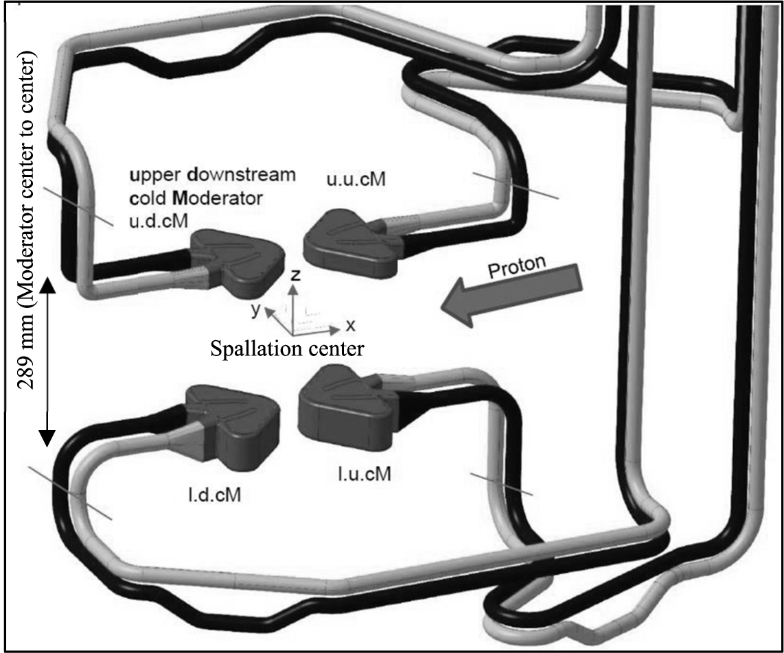
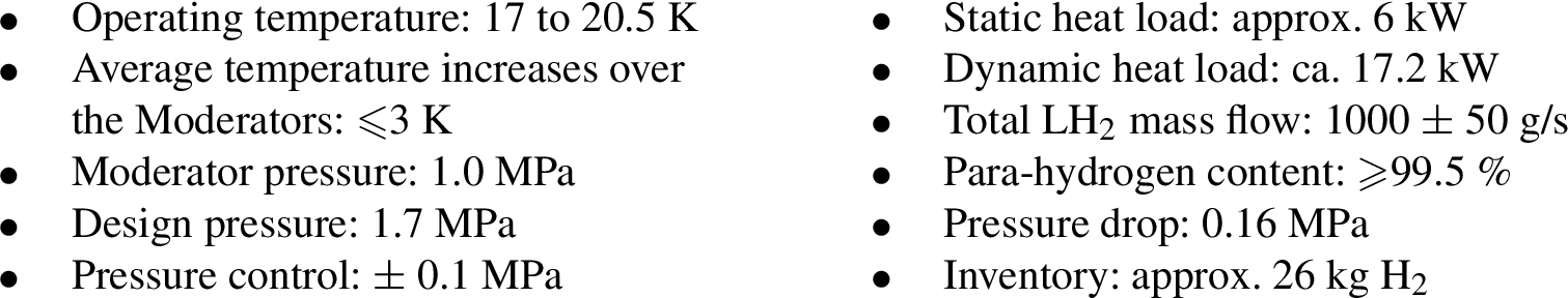
The hydrogen transfer lines supply liquid hydrogen from the CMS cold box towards the Twister that is able to hold up to four hydrogen Moderators. On the first 35 m the bulk flow is carried in a single vacuum insulated pipe with multilayer insulation (MLI) and gets split into four lines in the distribution box. These four lines are routed 10 m inside of the Target Monolith to a single vacuum chamber located on the Twister head (see Fig. 4). Removable u-shaped bayonets (Johnston couplings) are connected to each distribution line with the pipe inside the Twister that guides the flow to the Moderator and back. The parallel flow allows operating each Moderator with the same supply temperature and results in less pressure loss. Four return lines are connected again to the distribution box. Four control valves adjust the flow so that 240 g/s are being supplied to each of the two upper low dimension Moderators (30 mm hydrogen height) and 260 g/s to each of the two lower volume Moderators (60 mm hydrogen height). Figure 3 shows the arrangement of the ESS cold Moderator unit, which consists of four pressure vessels. These vessels represent the so-called butterfly Moderators (BF2). Each consists of two vessels face to face. The two upper vessels are identical and differ from the two lower vessels only in their height. The four flows get united again and take the bulk return line to the CMS cold box. The heat load by neutrons is pulsed and amounts to approx. 17.2 kW [9] in total for the BF2 Moderators. In addition, a static heat load of about 6 kW due to losses in the circuit needs to be considered. This results in a total heat load of at least 23.2 kW at full beam power, which is why the TMCP was designed for up to 30 kW. The main parameters of the CMS are summarized below:
During the final design phase, it was decided that the two lower para-hydrogen Moderators should not be implemented, which is why this area will initially remain unequipped and will be available for future cold Moderator upgrades.
Fig. 4.
First-generation ESS Twister: a) upper MRP, b) Moderator support structure with upper MRP, c) outer stainless-steel reflector, d) final assembly developed and built by Central Institute of Engineering, Electronics and Analytics (ZEA-1).
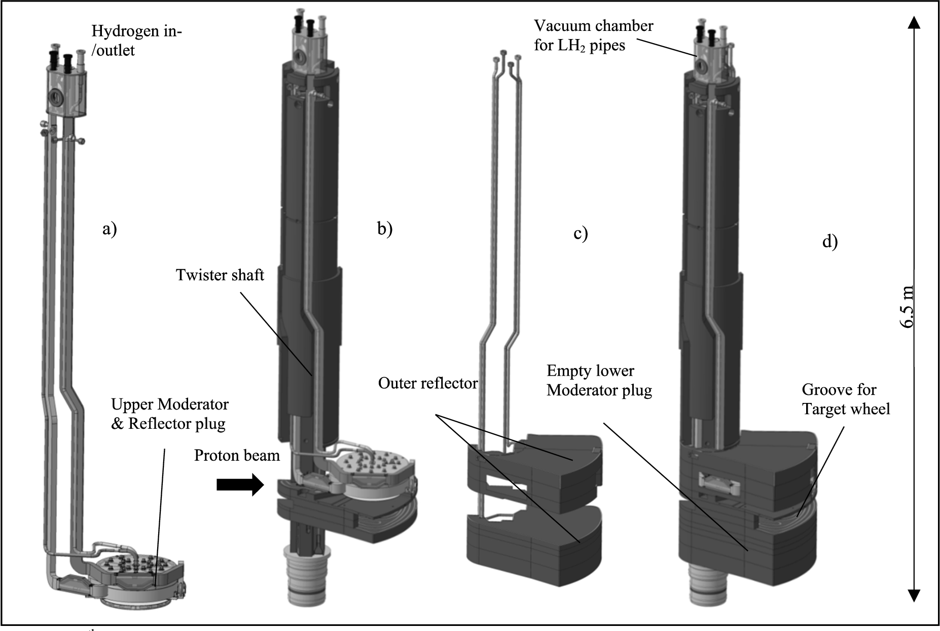
3.Moderator & Reflector support and handling structure (Twister)
The first-generation of ESS Moderator & Reflector support and handling structure, the Twister primarily includes the two mentioned liquid para-hydrogen low-dimension Moderators (BF2), arranged above the tungsten Target wheel around the spallation centre. Furthermore, a light-water pre-Moderator, a light-water thermal Moderator and a beryllium reflector are part of the upper Moderator & Reflector Plug (MRP), which is surrounded by a stainless-steel frame cooled by light water. The lower MRP of the first generation is replaced by a water-cooled stainless-steel block. In total nine independent water-cooling loops, two liquid-hydrogen loops and a vacuum jacket have to be routed through the Twister shaft to provide the needed amount of cooling fluid to the individual components. To comply with shielding requirements, all pipes have a parallel offset on the halfway to avoid a direct view to the main radiation area of the Target. The structure, shown in Fig. 4, has a height of 6.5 m and a weight of 13000 kg. The name Twister comes from the handling sequence in which it must first be rotated (or twisted) out from the target wheel before it can be lifted. The only component of the CMS that is irradiated is the Twister, which is why it has to be replaced periodically after the radiation-related lifetime has been reached. The lifetime of the entire Twister is determined by the lifetime of the aluminium components, especially the Moderators. The Aluminium alloy 6061-T6 is able to withstand up to 40 displacements per atom (dpa) under irradiation, which is reached after operation of about 1.5 years or 7000 h at full beam power [6]. The Moderators are highly integrated, and the surrounding components are highly activated, which is why the Moderators cannot be partially dismantled, so that always the entire Twister has to be replaced. As a result, however, a continuous optimization and further development of the Moderator & Reflector environment to comply with new needs of the users of the facility is always possible.
4.First and second generation of para-hydrogen Moderators (BF2 and BF1)
Latest particle-transport simulations performed at the ESS have shown that the neutron yield can be increased by up to 30% for some beamlines by optimizing the existing cold Moderator (BF2) [8]. The BF2 Moderator concept consists of two independent heart-shaped hydrogen pressure vessels located face-to-face and forming together a kind of butterfly (see Fig. 5 left). In between these vessels, a thermal H2O Moderator is installed. In contrast, in the new Moderator concept the thermal Moderator in the centre is removed and the two hydrogen vessels are connected. This results in a single hydrogen Moderator in the shape of a butterfly (BF1) as shown in Fig. 5 on the right. Most instruments would accept the loss of thermal neutrons for the better yield of cold neutrons.
Fig. 5.
Engineering design of the first (BF2, left) and second (BF1, right [1]) generation of ESS para-hydrogen Moderators, showing horizontal sections through the center of the Moderators including fluid guide structure.
![Engineering design of the first (BF2, left) and second (BF1, right [1]) generation of ESS para-hydrogen Moderators, showing horizontal sections through the center of the Moderators including fluid guide structure.](https://ip.ios.semcs.net:443/media/jnr/2022/24-2/jnr-24-2-jnr220033/jnr-24-jnr220033-g006.jpg)
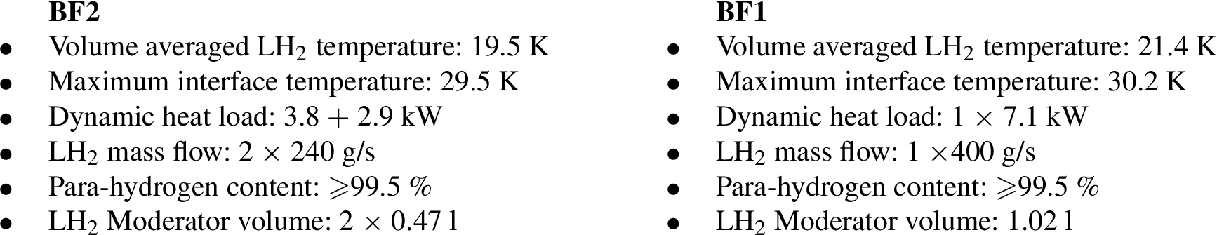
However, from an engineering point of view, the higher neutron yield also entails a higher heat load, especially since only one coolant circuit is available for removing the particle heat. Nevertheless, a detailed study [1] has shown that the new BF1 concept can be implemented under certain conditions, which is why ESS decided that the BF1 will be used in the upper Moderator plug of the 2nd generation of ESS Moderators. The main parameters determined from CFD and FEM simulations are as follows:
It should be noted that the decision to use the BF1 Moderator would probably no longer allow to install, as originally planned, another set of hydrogen Moderator in the lower Moderator plug (with 60 mm hydrogen height) due to the limited capacity of the existing TMCP. On the other hand, additional cryogenic infrastructure or upgrades of the existing infrastructure would be anyway required if the currently discussed deuterium Moderator upgrade should be realized.
Fig. 6.
Preliminary CAD design of a liquid ortho-deuterium Moderator for future ESS Moderator upgrades [7].
![Preliminary CAD design of a liquid ortho-deuterium Moderator for future ESS Moderator upgrades [7].](https://ip.ios.semcs.net:443/media/jnr/2022/24-2/jnr-24-2-jnr220033/jnr-24-jnr220033-g008.jpg)
5.Future Moderator upgrades at ESS
The first and second design generation of ESS Moderators consists of the BF2 or BF1 Moderator only. These Moderator(s) are installed in the upper part of the Twister above the tungsten Target wheel. However, the Twister allows also to use the space below the Target wheel for future Moderator upgrades. This location is characterized, like the upper part of the Twister, by its proximity to the spallation center and thus a large neutron flux. The disadvantage is the enormous heat load caused by the 5 MW proton beam, which let it seem unlikely that one can place there a solid moderator for production of very cold neutrons (VCN) or a source for ultracold neutrons (UCN). It might, however, be possible to implement a large liquid-deuterium volume moderator with still manageable heat load, which will therefore be further investigated.
Based on the particle-transport simulations performed by the ESS neutronic team, a first draft engineering design of a volume deuterium Moderator shown in Fig. 6 was created. The major challenge is to handle the enormous heat load of around 56.6 kW [7]. For this a mass flow of at least ⩾3400 g/s liquid deuterium is needed to keep the average temperature increase, as required, below ⩽3 K. The design foresees the Moderator to be made of high strength aluminum alloy Al6061-T6, which allows local stresses up to 87 MPa and will be filled with approximately 34 l of liquid deuterium. The cold Moderator will be surrounded by a vacuum jacket followed by a light water pre-moderator and a beryllium reflector. In addition, a cold beryllium filter (⩽80 K) is installed inside the cold Moderator vessels at the neutron beam window 2 as shown in Fig. 6.
The fluid guides ensure that flow separation, dead areas and swirls do not occur. The extension rods ensure additional mechanical stability since the vessel walls are flat and need to be as thin as possible to minimize neutron losses. The main parameters determined from CFD and FEM simulations are summarized below:

References
[1] | Y. Beßler, Fluid Mechanical Simulation and Experimental Validation of the Cryogenic Hydrogen-Moderator for the European Spallation Neutron Source ESS, RWTH Aachen University, 2020. doi:10.18154/RWTH-2020-04622. |
[2] | Y. Beßler et al., The cryogenic moderator system cryostat design for the European spallation source, J. Phys.: Conf. Ser. 1021: ((2018) ), 012080. doi:10.1088/1742-6596/1021/1/012080. |
[3] | European Spallation Source ERIC. ESS Technical Design Report. Lund: European Spallation Source ERIC, 2013. ISBN: 978-91-980173-2-8. |
[4] | M. Klaus et al., Conceptual design of the liquid hydrogen moderator cooling circuit for the European spallation source, Physics Procedia 67: ((2015) ), 147–152. doi:10.1016/j.phpro.2015.06.026. |
[5] | M. Klaus et al., Expansion vessel for supercritical hydrogen in a spallation neutron source moderator circuit, Conf. Ser.: Mater. Sci. Eng. 101: ((2015) ), 012050. doi:10.1088/1757-899X/101/1/012050. |
[6] | Y. Lee and M. Hartl, ESS Materials Handbook. Materials Group, Target Division, European Spallation Source ERIC, Lund, (2016) , ESS-0028465. |
[7] | V. Santoro et al., Development of a High Intensity Neutron Source at the European Spallation Source: The HighNESS: Project Physics > Instrumentation and Detectors, (2022) . doi:10.48550/arXiv.2204.04051. |
[8] | L. Zanini et al., The Neutron Moderators for the European Spallation Source, J. Phys.: Conf. Ser. 1021: ((2018) ), 012066. doi:10.1088/1742-6596/1021/1/012066. |
[9] | L. Zanini and K. Batkov, Updated Heat Deposition of the Mark I and Mark II ESS Moderators, European Spallation Source ERIC, Lund, (2017) . |


