
The ESS monolith vessel design and possibilities to introduce a UCN/VCN source
Abstract
The ESS ERIC neutron source design includes a helium cooled tungsten spallation target and a liquid hydrogen moderator, enclosed in a vacuum vessel (the monolith vessel). The neutron source and moderator are shielded by stainless steel and casted iron to block neutron and gamma radiation emitted in directions other than along the neutron beam ports. After the ESS concept design was approved, questions were raised if it was possible to introduce a UCN/VCN (Ultra Cold Neutron/Very Cold Neutron) source into the ESS design. Since the shielding concept of the monolith vessel is to 100% fill the monolith void except for the proton and neutron beam paths, there are no cavities in the monolith vessel left, where one could easily place a UCN/VCN source. An additional challenge is the pipe routing for the UCN/VCN cooling media. However, some of the shielding blocks and monolith components are removable and could possibly be redesigned, enabling implementation of a UCN/VCN source. This article presents a feasibility study how to physically introduce a UCN/VCN source in the present ESS design, focusing on the geometrical possibilities. Four possible locations for the UCN/VCN source were identified, which are considered to be feasible but will require some redesign of the monolith vessel shielding.
1.Introduction
1.1.Monolith vessel design
The ESS monolith vessel is a vacuum chamber, 6 m in diameter and 7 m of height. The basic functions are to enclose the neutron source (the target wheel), optimize the neutron flux (by having vacuum inside the monolith vessel) and shield the scientific instruments and the workers from neutron and gamma radiation (by means of metallic shielding blocks). Figure 1 visualizes the monolith vessel (shielding blocks outside of the monolith vessel are extracted to overview the monolith vessel). Figure 2 is a section cut of the monolith vessel visualizing the target wheel (containing the tungsten spallation material for neutron production), the moderator twister (containing the liquid hydrogen moderator, the water moderator and the beryllium reflector), the proton beam instrumentation plug and the proton beam pipe. The inner shielding above these components is not shown in this overview layout of the monolith vessel components.
Fig. 1.
Monolith vessel. The shielding outside of the monolith vessel is excluded to better view the monolith vessel.
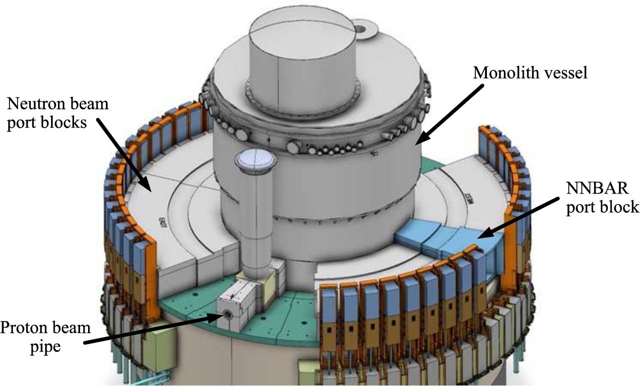
Fig. 2.
Section cut of the monolith vessel (inner shielding not shown), see explanation in the text.
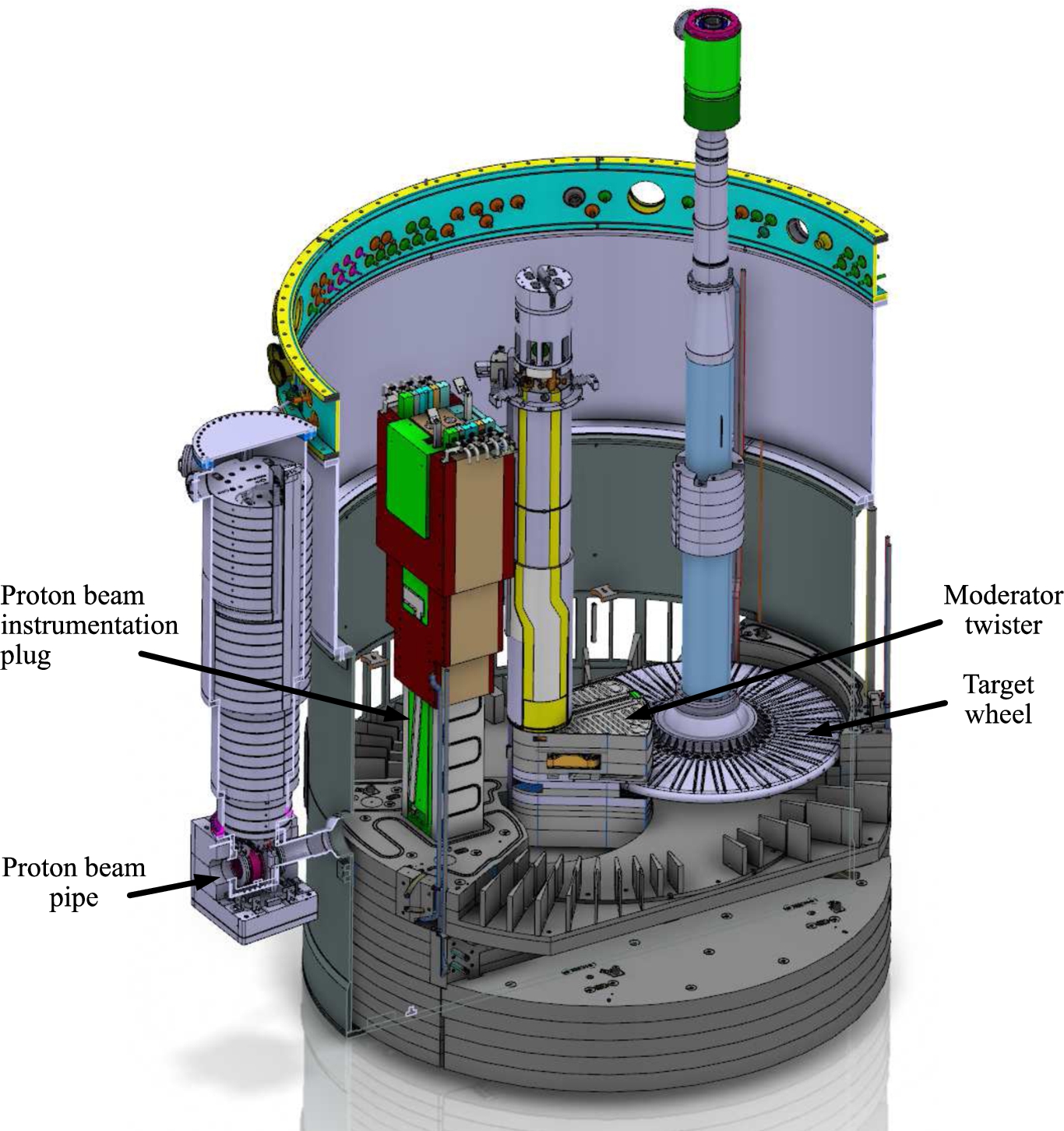
Fig. 3.
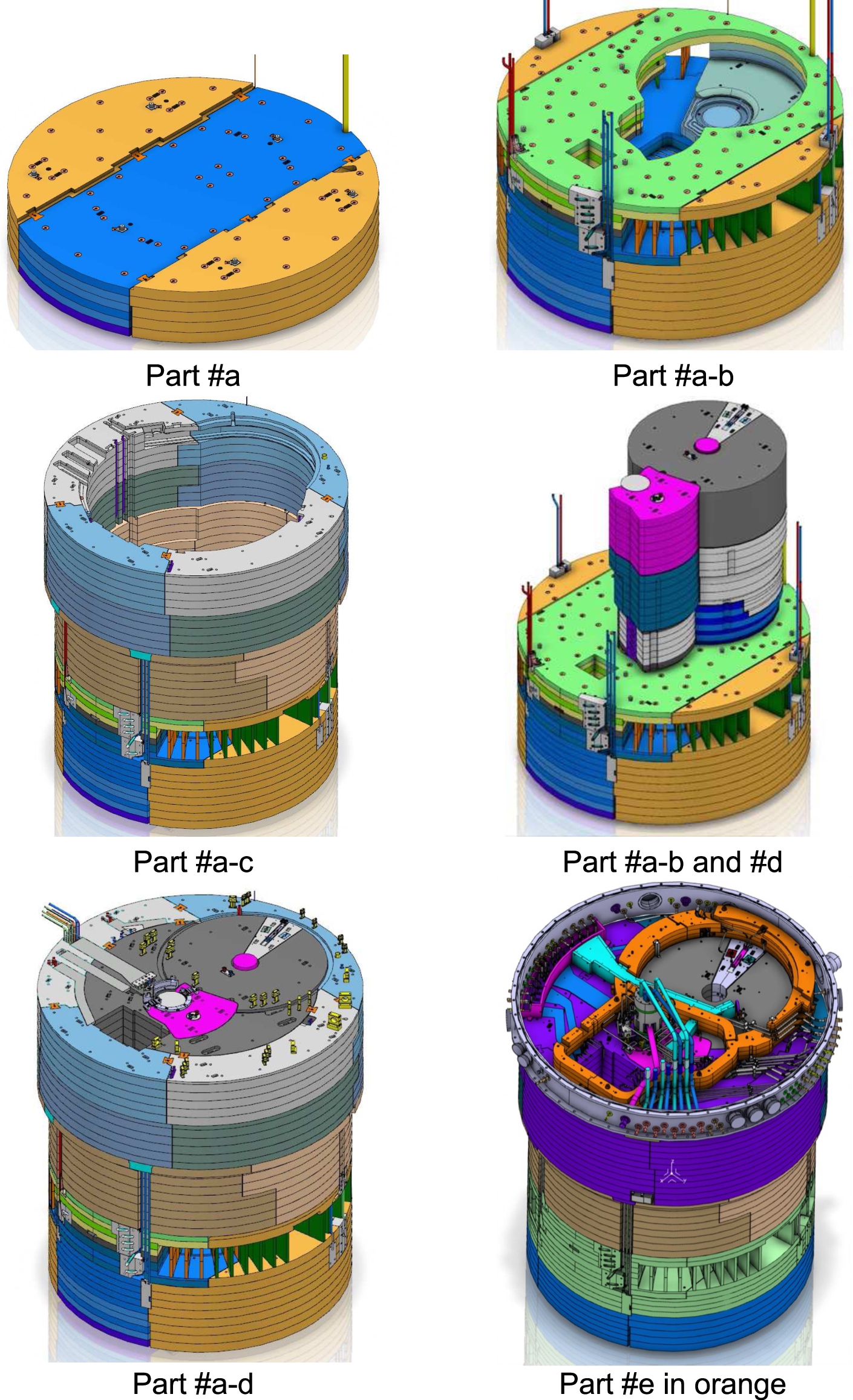
Inner shielding, see explanation in the text.
1.2.Shielding design
To properly shield the neutron source, any cavity inside the monolith vessel, not intersecting the proton or neutron beamlines, is filled with stainless steel. The shielding is divided into five groups depending on specific requirements (Fig. 3).
#a. Bottom shielding, supporting the proton beam instrumentation plug, the moderator twister and the target wheel;
#b. Middle part, consisting of water-cooled shielding blocks to handle the heat load from the spallation process in the target wheel;
#c. Top part, consisting of uncooled shielding blocks;
#d. Removable shielding blocks above the target wheel and the moderator twister, lifted out when these components are to be replaced for maintenance;
#e. Blocks to interface the waste casks when irradiated components are lifted out of the monolith vessel.
2.Possible positions to install a UCN/VCN source
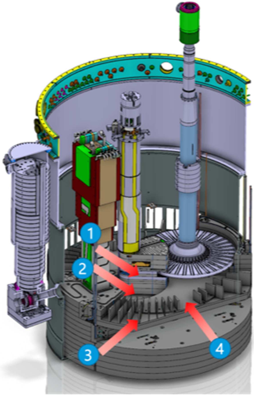
The monolith vessel, the shielding and the monolith vessel components were developed to optimize the neutron flux to the scattering instruments. The final design is based on the requirements and concept design given in the ESS Technical Design Report [2] and the System Definition and Solution Design Description [1]. Four locations in the monolith vessel have been identified as possible candidates for implementation of a UCN/VCN source. They all will require some reconstruction, and some of them will also occupy one or several neutron beam ports. The four locations are (see Fig. 4):
#1. Moderator twister, lower position;
#2. Moderator shielding block (also named Moderator cooling block);
#3. Neutron beam port insert;
#4. NNBAR port block.
A further discussion of UCN/VCN sources implemented in the four locations can be found in Ref. [3].
Fig. 4.
Possible locations #1–4 of the UCN/VCN source. See explanation in the text.
2.1.Location #1
The moderator twister was originally designed to hold two neutron moderator/reflector systems, one above the spallation target and one below. The monolith vessel has been designed with the requirement that two moderator/reflector positions are possible, and that from all the neutron beam ports it is possible to view both moderator positions. In the present ESS neutron source configuration, only the top position is used. The bottom position is presently occupied by a steel plug, but can accommodate a second source without interfering with the presently planned neutron instruments.
When the top moderator, on routine basis, needs to be exchanged, the complete moderator twister is removed and replaced. A next-generation moderator twister could include a UCN/VCN source in the lower position (Fig. 5). The UCN/VCN source size is limited to the existing moderator twister dimensions. The piping for the UCN/VCN cooling media needs to be routed in the moderator twister shaft. Preliminary studies indicate this to be possible.
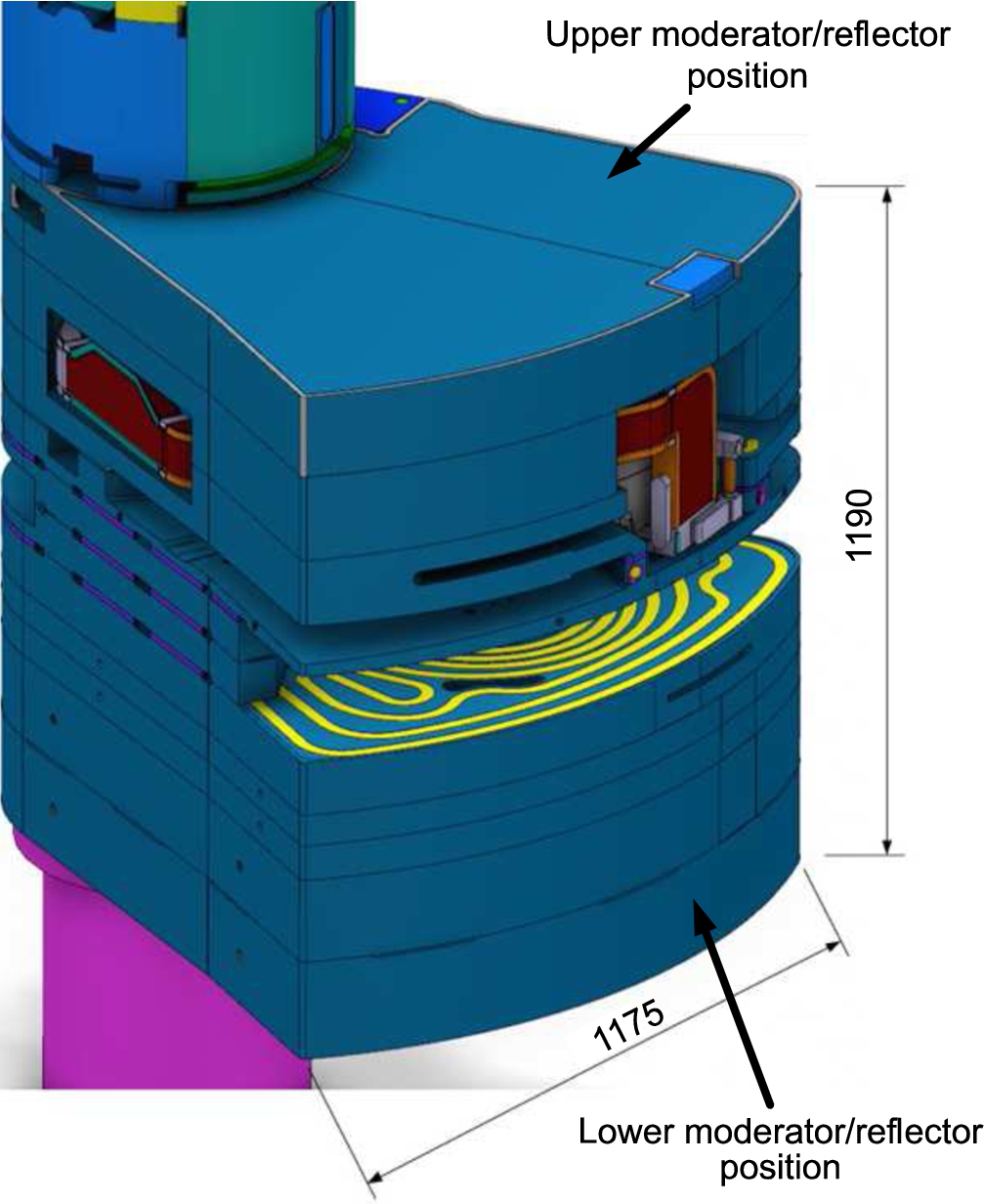
Fig. 5.
Moderator twister – top and bottom position. Dimensions in mm.
2.2.Location #2
Once the moderator twister is lowered down into the monolith vessel, it is twisted over the target wheel into its final position (Fig. 6). This opens up a cavity which, at a later stage in the moderator twister installation sequence, will be filled by the moderator shielding block (Fig. 7). This block can be designed to include a void, where a UCN/VCN source can be placed, as shown on the right in Fig. 7. Neutrons can be extracted through beam ports facing this position. The pipe routing for the UCN/VCN source is foreseen to be included in the moderator shielding block shaft (see Fig. 7 left picture).
Fig. 6.
Moderator. The possible UCN/VCN location is in front of the moderator.
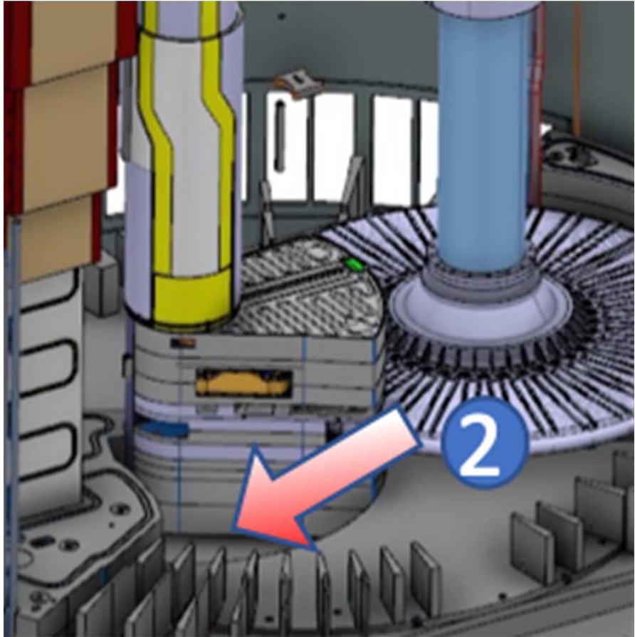
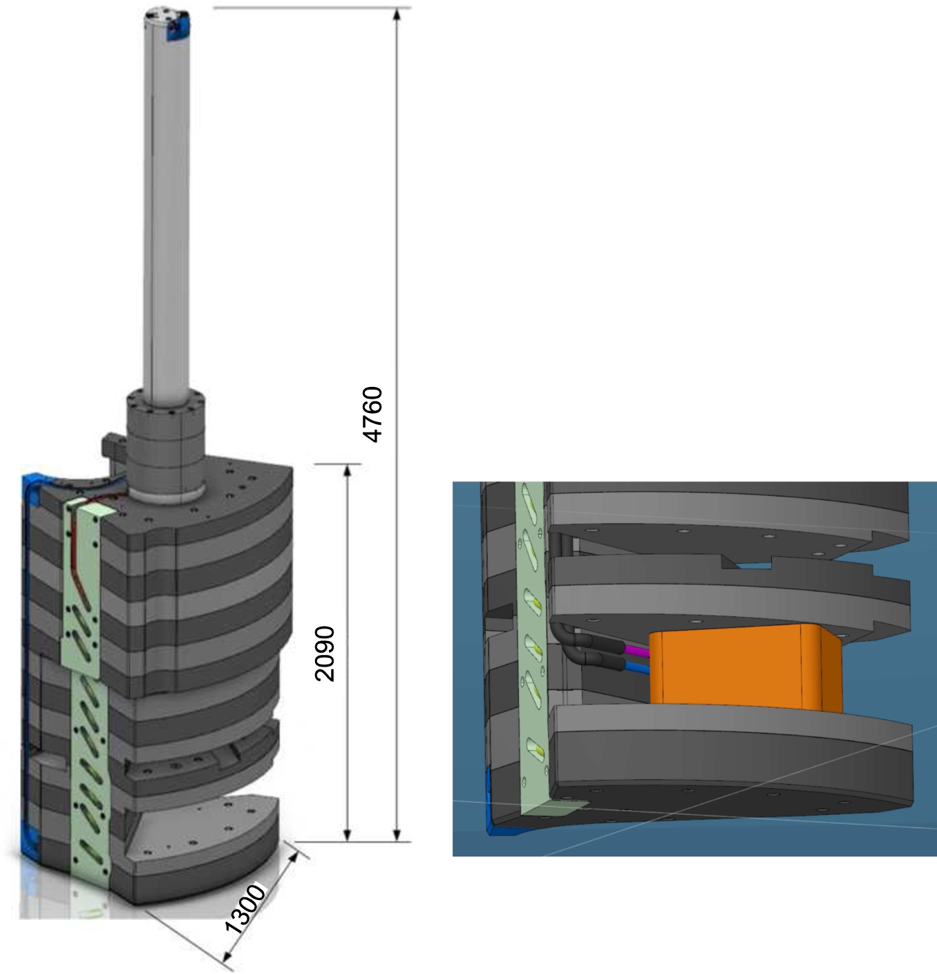
Fig. 7.
Location option #2 for a UCN/VCN source. Left: moderator shielding block. Right: possible UCN/VCN source holder (orange) integrated in the lower part of the moderator shielding block. Dimensions in mm.
2.3.Location #3
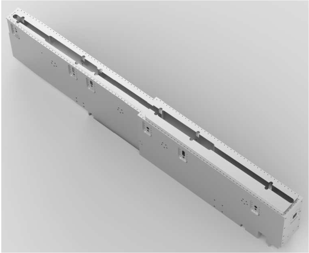
Inserted in the monolith (Fig. 8), the neutron beam port inserts (NBPIs, see Fig. 9) are replaceable steel components which are 3.5 m long and start at 2 m from the moderator center.
These inserts are either closing unused beamlines (blind plugs), or include neutron guides. A neutron beam port insert could be redesigned to include a UCN/VCN source, which would then be limited by the available space in this location. The pipe routing for the UCN/VCN source needs to be arranged inside the specific NBPI as well, which needs to be further elaborated.
Fig. 8.
Horizontal section cut at the level of the top moderator position. The moderator assembly is visible in the center, and two neutron beam port inserts (grey) to the right.
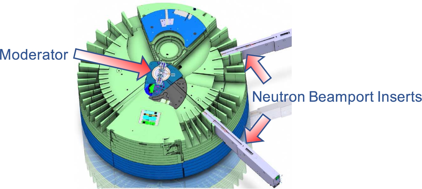
Fig. 9.
Neutron beam port insert (left part facing the neutron source).
2.4.Location #4
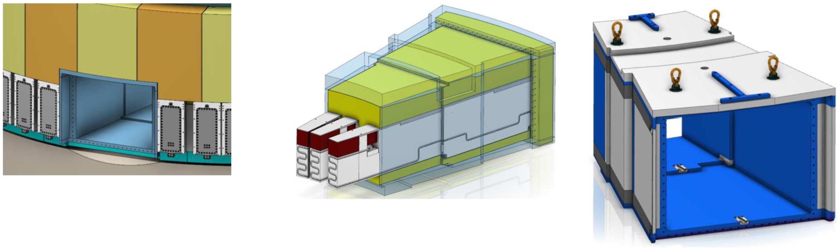
The location uses the NNBAR port block (see Fig. 10). By extracting the NNBAR insert and the three NBPI’s, the resulting port block cavity is the largest of the four possible locations for the placement of a UCN/VCN source in the ESS monolith vessel. The pipe routing for the source in this location is inside the NNBAR port block.
Fig. 10.
Large beam port in ESS shielding monolith. Left: front view on NNBAR port block included in the monolith, middle: NNBAR insert filled with three NBPI’s; right: NNBAR port block.
3.Summary and outlook
There are different engineering aspects to consider for the four locations. The insertion of new sources will impact the present design to a variable extent, and each position geometrically limits the maximum size of the UCN/VCN sources. The largest volume is offered in location #4, with the NNBAR insert (shown in Fig. 10, middle) extracted. However, the position can be used for a UCN/VCN source only after completion of the NNBAR project.
Due to the presence of a large number of unused neutron beam ports at ESS, the location #3 will not interfere with any other instrument at the ESS, as the UCN/VCN source would replace a port plug of a single neutron beam port. The disadvantage of the location #3 is the beam port geometrical limitation, and that the UCN/VCN piping needs to be included in the beam port.
In the present design of the ESS, the cavity of location #2 is filled with a water-cooled shielding block. This block could be redesigned to include then a UCN/VCN source, which would be size-limited according to the geometry of the block. Since the shielding block is designed to be removed during the recurrent replacement of the moderator twister, it can be fairly easily replaced by such a modified block. This replacement is possible during any longer shutdown of the ESS.
Finally, in location #1 the UCN/VCN source would occupy the ESS “empty” moderator position. The concept design of the ESS neutron source foresees the possibility to place one moderator system above and one below the target wheel. During elaboration of the moderator design, it was decided to implement only the upper moderator. The UCN/VCN source would occupy the lower position, which requires the next generation of the moderator twister to be designed accordingly. The source would then become available after exchange of the twister, on occasion of replacement of the ESS moderator system.
References
[1] | P. Nilsson, SDD-Sol target station, ESS-1423053, 2022. |
[2] | S. Peggs, ESS technical design report, 2013. ISBN 978-91-980173-2-8. |
[3] | L. Zanini et al., Very cold and ultra-cold neutron sources for ESS, these proceedings. |


