
Concept and strategy of SuperSUN: A new ultracold neutron converter
Abstract
A new source of ultracold neutrons (UCNs), developed at the Institut Laue-Langevin (ILL) and named SuperSUN, is currently being commissioned. Its operational principle is the conversion of cold neutrons, delivered by ILL’s existing beam H523, to UCNs in a vessel filled with superfluid helium-4, wherein the neutron’s energy and momentum are transferred by inelastic scattering to phonons in the superfluid. The inverse Boltzmann-suppressed process is negligible at temperatures below 0.6 K, enabling long storage times and high in-situ UCN densities as demonstrated at the ILL for two prototype sources. These two prototypes are installed at secondary beams behind crystal monochromators, whereas a primary beam with a white cold spectrum illuminates the SuperSUN conversion volume. This provides not only higher intensity around the wavelength 0.89 nm where the dominant single-phonon process for UCN production takes place, but also a contribution to UCN production by multi-phonon processes. In the first phase of the project, material walls will trap the UCNs, while in the second phase an octupole magnet will generate a 2.1 T magnetic field at the edge of the conversion volume. For low-field-seeking UCNs, this field increases the trapping potential and reduces wall losses so that the accumulated UCNs are spin-polarized as a result. SuperSUN aims to deliver the highest possible UCN densities to external storage experiments, the first of which will be the PanEDM experiment measuring the neutron’s permanent electric dipole moment.
1.Introduction
In 1959 Zeldovich described the possibility to store neutrons in a material container, exploiting the neutron optical potential of its walls [41]. Storable neutrons typically have a kinetic energy
The saturated density, to which one can accumulate UCNs in the closed converter, is proportional to the time constant τ and the UCN production rate density P:
There are various ways to exploit UCN production in a superfluid-helium converter. One obtains the highest UCN production rates by placing the converter in-pile in the high-flux region close to the core of a nuclear reactor or a spallation target [24,33]. A difficulty in this approach is that the large heat load requires a powerful cryogenic plant, even for source operation above 1 K where up-scattering dominates UCN losses [35]. An interesting alternative, already pointed out in [14], places the converter at the end of a neutron guide. Located in-beam far away from the hot zone of a primary source, the UCN production rate in this approach is much lower than in-pile, but the low heat load makes temperatures below 0.6 K achievable, thus removing up-scattering as a limitation. By also suppressing the neutron absorption and wall losses with respect to the neutron lifetime, one can achieve competitive UCN densities in a source that can feed an experiment in close proximity and, hence, with limited UCN transport losses. Further implementations of the in-beam concept even place experiments in-situ, immersed in the superfluid-helium bath of the converter [3,7,16,38].
The new ILL instrument SuperSUN is the result of a development effort to offer the user community an in-beam accumulation-type UCN source, feeding external experiments via a UCN extraction guide at room temperature.
2.The SUN-1 and SUN-2 accumulation-type UCN source prototypes
In preparation for the project SuperSUN, the development of a first prototype (now called SUN-1) was launched at Munich in 2004 [42,43], and after 2007 continued at the ILL [27,45]. A second prototype, SUN-2, was constructed at the ILL and is currently used for tests of concepts and development of tools and components for UCN physics. Key features of both devices are a short (<40 cm) vertical guide section for UCN extraction, and a cold UCN valve above the converter, enabling accumulation and release of the UCNs to an experiment (or detector) at room temperature. In contrast to an earlier attempt to extract UCNs in the horizontal plane [18], this method of operation requires neither a UCN transmitting window in the converter vessel, nor significant gaps between the converter and the guide, thus avoiding associated UCN losses.
Modest cooling power is needed to maintain the converter below 0.7 K: 0.6 K was achieved with the SUN-2 heat exchanger with an applied heat load of 60 mW and a 3He flow rate of 35 g/h [21]. The cooling method employs pumping on a 3He bath in contact with one side of a finned copper heat-exchanger, the other side of which is immersed in the isotopically pure superfluid 4He of the UCN converter. The cold-head of a commercial Gifford–McMahon cryocooler precools the gas in a closed 3He circuit, using a spiral heat-exchanger between its two stages [32]. A 4He evaporation stage (called “1-K pot”), also operated in a closed circuit, serves for liquefaction and further precooling of the 3He. The cryostat of SUN-1 is designed to liquefy 4He from a gas bottle, without requiring an external supply of liquid helium. The main part of the liquefied helium then fills the converter through the 1-K pot (see reference [27] for more details). SUN-2 is equipped with a large (14 L) 1-K pot which can be filled by siphoning liquid helium from a dewar. This, along with a generally improved design involving a second cold-head for cooling thermal screens, reduced the time for cool-down and preparation of the converter from one week (SUN-1) to less than three days. In both devices, a superleak connected to the 1-K pot purifies the helium for the converter from 3He (see reference [43] for the procedure used to produce the superleaks employed in both source prototypes).
The compactness of the sources is noteworthy since this makes them a flexible tool for application in physics experiments. The possibility to transport them between neutron beams with different characteristics has been exploited to perform measurements at ILL’s cold neutron beam facility PF1B. SUN-1 was used there to measure UCN production in pressurized superfluid helium, resolving single- and multi-phonon processes by using a neutron velocity selector in the incident cold beam [30]. SUN-2 was used similarly in a measurement of UCN production and up-scattering in superfluid helium in the temperature range
Each source prototype is currently located at a separate secondary beam produced by diffraction using an independent crystal monochromator. These are made of pyrolytic graphite and intercalated potassium layers, with different lattice constants, to obtain two different diffracting angles for the two devices [6]. Mounted on a common goniometer, they can be rotated to deviate the full area (
Table 1
Comparison of SUN-1, SUN-2, and SuperSUN with respect to their incoming cold neutron flux, converter volume, (expected) saturated UCN density, and storage time constant. For SuperSUN the stated flux corresponds to the capture-weighted flux for the entire beam, integrated over all wavelengths. The wavelength range around 0.89 nm for production of UCNs up to 250 neV corresponds to 0.7% of the total beam current
| UCN source | 0.89 nm differential particle flux | Integral capture flux | Volume [L] | Density [ | Storage time constant [s] |
| SUN-1 | 5 | 55 | 43 ± 1 | ||
| SUN-2 | 3.8 | 220 | ≈200 | ||
| SuperSUN phase I | 14 | 330 | ⩾200 |
3.SuperSUN design principles
Building on prior experience with the SUN prototype sources, SuperSUN was launched as an instrument project within the ILL’s upgrade program “Endurance”. In contrast to the prototypes, SuperSUN exploits the direct cold neutron beam from the H523 beamline, previously used for CryoEDM [38]. Eliminating the losses due to beam monochromatization results in a higher intensity at 0.89 nm, and the presence of shorter-wavelength neutrons that increase the UCN yield via multi-phonon processes. A 30% relative increase was measured using an earlier version of the beamline that feeds the SuperSUN instrument position [5]. Such large gains cannot be expected for a long converter where the short-wavelength component will be rapidly attenuated by scattering. For our geometry, this component will mainly be present in the first meter of the converter vessel and a simple estimate suggests a ≈10% contribution due to these processes.
The H523 beamline is composed of
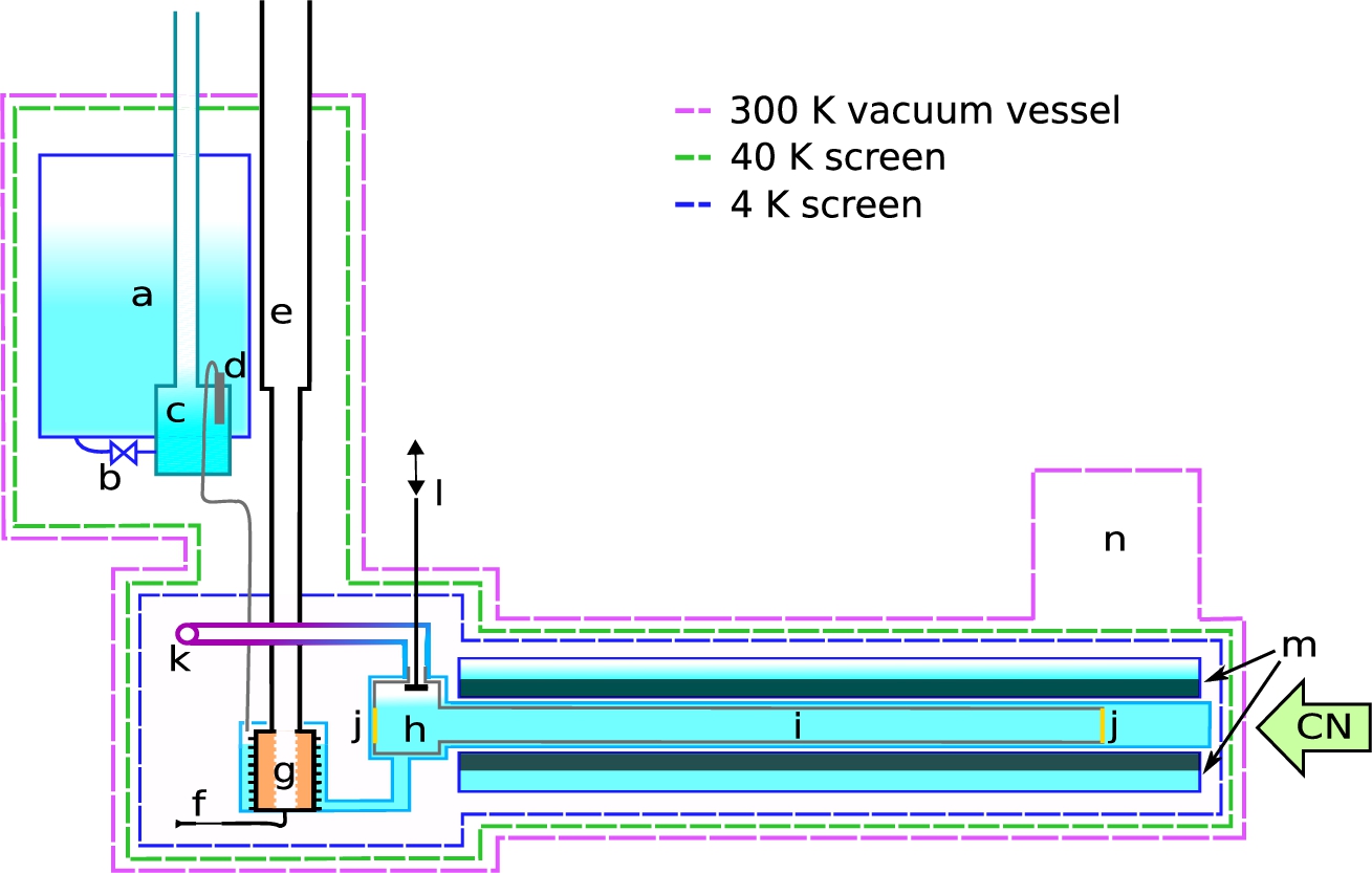
Fig. 1.
(Color online) Sketch of SuperSUN with (a) the 100-L liquid helium bath, (b) the needle valve, (c) the 1-K pot, (d) the 4He superleak, (e) the 3He pumping column, (f) the 3He impedance, (g) the 3He/4He heat exchanger, (h) the UCN box, (i) the conversion volume at 0.6 K, (j) the two beryllium windows, (k) the UCN extraction system, (l) the UCN valve, (m) the superconducting magnet in a separate liquid helium bath: for SuperSUN phase II this replaces part of the phase I 4-K screen, see description at the end of Section 3, (n) the 4-K cryostat. The cold neutron beam is represented by a green arrow labeled CN.
The SuperSUN phase I apparatus includes a UCN extraction system, the cryogenic cooling system, and the conversion volume with the “UCN box” that connects these elements together, as represented in Fig. 1. As motivated in the introduction, a design goal of SuperSUN is to cool its superfluid-helium converter down to 0.6 K to suppress the up-scattering losses (see Eq. (1) and Eq. (2)). The converter guide is 3 meters long with a diameter of 75 mm, leading to a volume of 14 liters intersected by the beam (compared to 5 and 3.8 liters in the prototypes SUN-1 and SUN-2, respectively). The longer converter vessel of SuperSUN increases the total number of UCNs that can be produced and accumulated. The associated cost of UCN density is expected to stay marginal: since the mean free path of 0.89 nm neutrons is about 17 m in superfluid 4He below 1 K [36], at the exit of the converter this beam component is attenuated by only about 17%. It is not presently known to what extent additional extraction losses may result from the extended converter volume, which is longer by approximately a factor of 3 in comparison to the first prototype source, SUN-1. Simulations and test experiments have indicated that the main impact could be a longer time-constant for filling the experiment, but this must be experimentally confirmed during source commissioning.
The cylindrical wall of the conversion volume guides the cold neutron beam to prevent loss of neutrons that can be converted into UCNs. Its second functionality is to store the produced UCNs to build up density before releasing them. The circular neutron guide, produced by S-DH GmbH [29], is made of Ni by the replica technique [28,34], and its inner surface is coated with a NiMo/Ti
The first element of the UCN extraction system is a UCN valve situated a few cm above the superfluid helium, which can release neutrons from the conversion volume into an extraction guide made of stainless-steel. For the phase II configuration, this guide will be modified to incorporate non-depolarizing wall coatings, and magnetic fields will be added to maintain adiabatic transport of the neutron polarization. The extraction guide consists of a short vertical section with 47 mm inner diameter, followed by two 90° bends connected by a 30 cm long horizontal section and continued by a final straight guide, all with a nominal inner diameter of 50 mm. To reduce the heat load due to thermal radiation guided by the high-reflectivity surfaces of the guide from its warm end into the converter, each bend includes two DLC-coated germanium disks that have a high transmission for thermal radiation and a high neutron optical potential. A black velvet layer that absorbs 98% of the infrared spectrum is placed behind each germanium disk, on the thermally-anchored copper flanges to absorb the thermal radiation. This concept has been proven successful in the single-bend UCN extraction system of SUN-2, for which simulations show a reduction of thermal radiative power by about 75%, and a neutron transmission of 92% as compared to a smooth elbow geometry [20]. A thin polypropylene foil possessing a neutron optical potential of
Fig. 2.
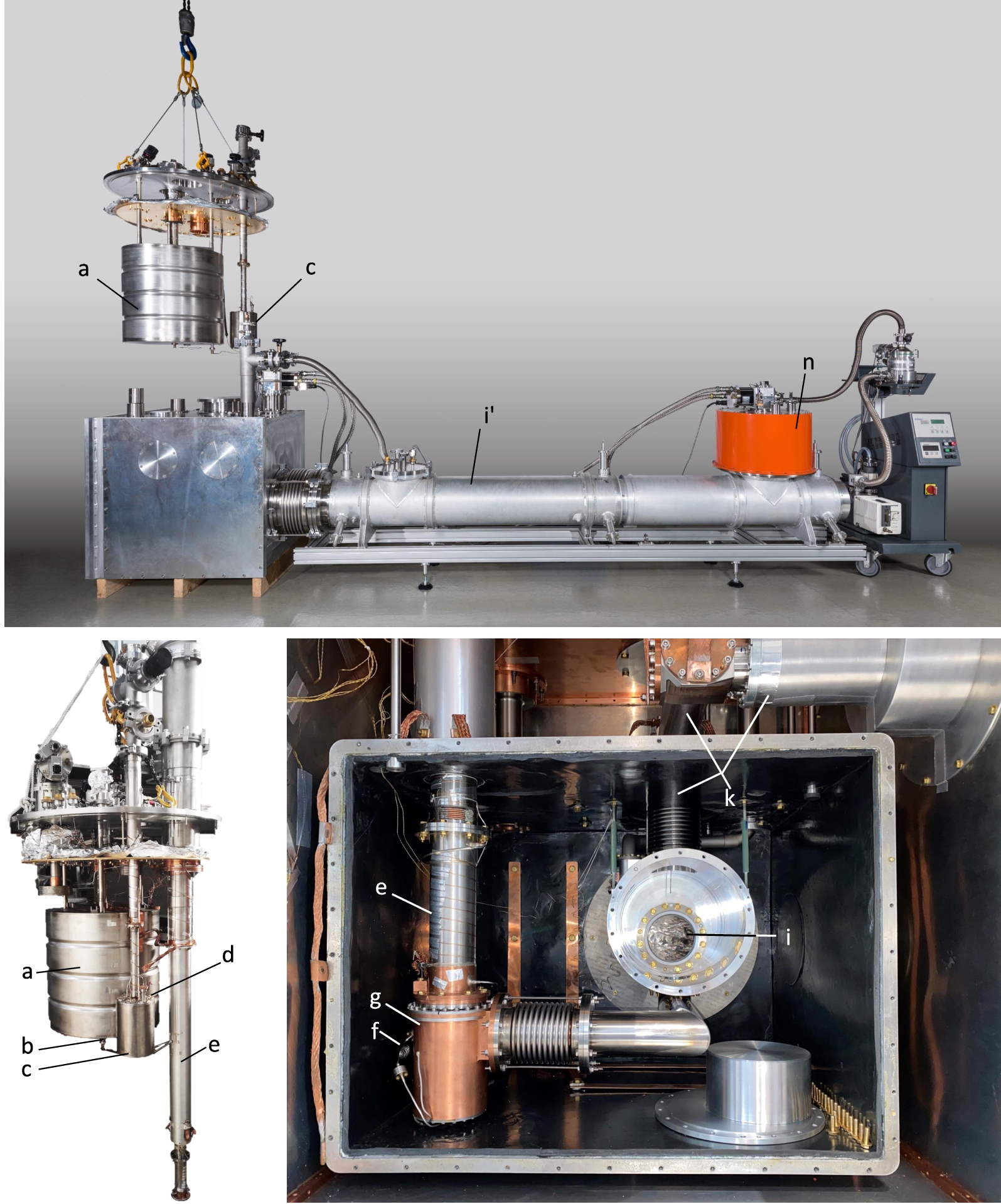
Pictures of SuperSUN with the same labeling as in Fig. 1: (a) the 100 L liquid helium bath, (b) the needle valve, (c) the 1-K pot, (d) the superleak, (e) the 3He pumping column, (f) the 3He impedance, (g) the 3He/4He heat exchanger, (i) the superfluid conversion volume, (i’) vacuum vessel containing the thermally screened conversion volume, (k) the UCN extraction system, (n) the 4-K cryostat. Credit top photo: Ecliptique – Laurent Thion.
The cryogenic system of SuperSUN is shown in Figs 1 and 2. It was designed to prepare the ultra-pure superfluid-4He converter and maintain it at 0.6 K during its operation as a UCN source. As a major difference compared to the source prototypes, it features a 100-L vessel that can be filled with liquid helium from a dewar, while maintaining the converter at its base temperature. As in the source prototypes this vessel fills a smaller 1-K pot (of 5 L volume in SuperSUN), with flow restricted by a cold needle valve, to precool and liquefy the circulated 3He gas and to provide superfluid 4He to the converter vessel. A superleak connected to this pot and made of fine alumina powder (see recipe for manufacture in [40]) retains the 3He when supplying the superfluid helium to the converter. The Joule–Thomson thermal expansion of the 3He is performed after a fixed impedance placed at the entrance to the 3He/4He heat-exchanger. The heat-exchanger was machined from a single piece of ultra-pure copper by electro-erosion. It provides finned surfaces on the order of
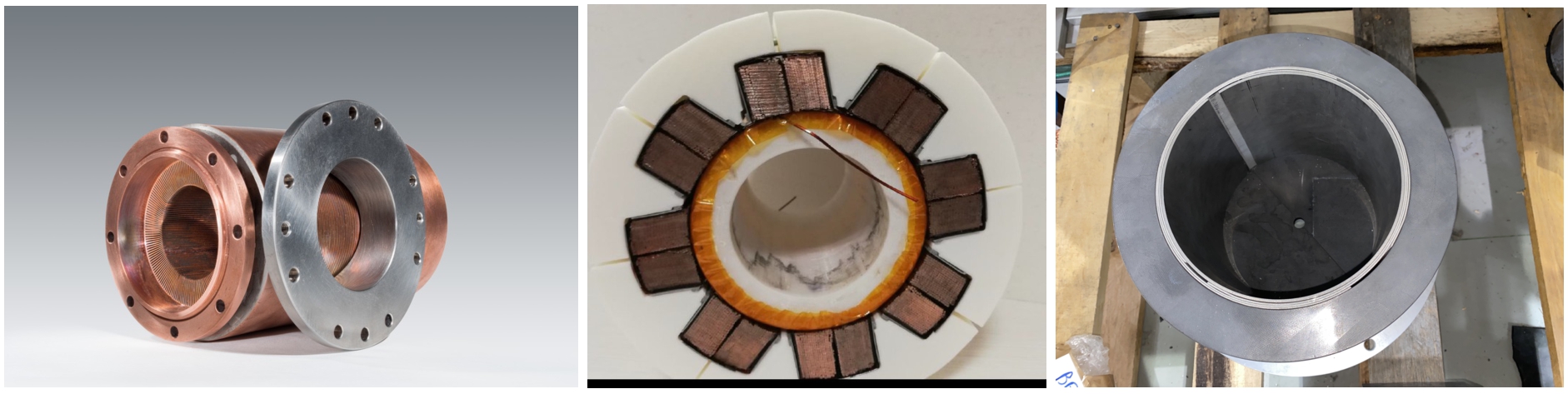
Fig. 3.
Left: picture of the 3He/4He heat exchanger, credit: Ecliptique – Laurent Thion. Middle: picture of a cut through a mockup of the octupole superconducting magnet. Right: picture of the beam-dump.
The entire cryostat, except for its two cylindrical turrets, is enclosed in a massive shielding structure whose purpose is radiological protection of the surrounding zones. The main structural element is a lead casemate supported by a stainless-steel frame. It is covered on its inner surfaces by B4C-loaded rubber mats for the absorption of cold and thermal neutrons. The cryostat itself also includes internal neutron-shielding elements, mainly to reduce the activation of components for which access and convenient handling should remain possible. A B4C aperture at the end of the octagonal guide admits as many neutrons as possible to the converter vessel, while capturing those that would miss the converter and potentially activate indium seals or other components in close proximity. The aperture diameter also preserves some margin to account for possible small misalignment with respect to the feeding guide. To avoid adding a heat load on the converter volume from the energy deposited in the B4C by neutron capture, this aperture is not mounted directly on the converter vessel but thermally anchored to the 4-K screen at a few mm distance. During the initial neutron test in 2021, a very restrictive aperture with a diameter of 20 mm was used, while in normal operation it will be much closer to the 75 mm diameter of the converter guide. Two layers of 0.1 mm thick gadolinium foils will be wrapped around the replica guide inside the superfluid containment vessel to reduce neutron-activation of the vessel itself, as well as other cryostat components around it. These neutron-absorbing layers unavoidably introduce an additional heat load on the coldest stage of the cryogenic system. The choice of Gd as a neutron absorber, rather than the 10B4C-coated aluminum foils (combined with thick B4C-enriched epoxy on the 4-K screen) that were used for initial testing, is dictated by two considerations. These are the smaller distance between the converter volume and the 4-K stage (in anticipation of the phase II configuration described below), and the relatively lower fraction of energy deposited locally by daughter products following neutron capture on Gd: this is considered as the main contribution to the difference in heat load. This approach nevertheless represents a conceptual departure from the design of the prototype sources, the implementation of which must be validated under real running conditions.
A beamstop is installed at the end of the beamline, to absorb any remaining neutrons and attenuate capture gamma rays; a picture of it is shown in Fig. 3. A 7.7 mm thick sintered boron carbide disk (with natural isotopic abundance) forms an end-cap, at the downstream end of a tube formed by rolled sheets of borated aluminum (4.5% of 10B, 3 mm minimum thickness). These dimensions are appropriate for absorbing the entire cold neutron beam that could be transported by the guide. This neutron shielding is surrounded by a 30 mm thick cylinder of lead with a 25 mm thick rear wall, in order to attenuate gamma rays produced by the neutron capture. Concentric holes of 11.5 mm diameter in the center of the boron disk and 20 mm diameter in the lead allow a small fraction of the neutron beam to reach a monitor detector outside the cryostat, but inside the lead shielding. Additional layers of B4C-loaded rubber behind the beam monitor absorb any remaining neutrons. This configuration fulfills the radiological safety criteria.
In its second phase, SuperSUN will be equipped with a superconducting octupole + solenoid magnet immersed in a liquid helium bath at 4.2 K as part of a dedicated cryostat (see Figs 1 and 3). The octupole magnet will generate a magnetic field with a radial gradient, reaching a value of 2.1 T at the cylindrical inner surface of the conversion volume, which enhances the trapping potential for low-field-seeking neutrons by 126 neV, thus repelling them from the wall. This will reduce not only the fraction of trapped UCNs hitting the material walls but also the energy and wall collision rate of those that do. As a result of the increased depth of the potential well and a longer UCN storage lifetime, large gains in UCN density can be expected. In addition, SuperSUN will become an intrinsically polarized UCN source without the need to polarize the incident cold neutrons [44]. To avoid non-adiabatic transport of the neutron polarization, which would lead to the loss of UCNs, a weak longitudinal field will be generated by a thin-layered solenoid between the converter and the octupole magnet. Moreover, the extraction system will be modified to avoid losses due to depolarization in the stainless steel guides.
4.Status and outlook
SuperSUN was designed based on the prototypes SUN-1 and SUN-2, to convert the cold neutrons from the H523 beamline into UCNs using superfluid helium at temperatures below 0.6 K. The main improvements from the prototypes are (1) the use of an undeflected, primary cold neutron beam, (2) a more efficient heat exchanger, (3) a larger conversion volume including a
SuperSUN in its phase I configuration was fully assembled at its H523 beam position in 2021 and cold neutrons were delivered into the running cryostat with a B4C aperture blocking all but 8% of the beam. Prior to this test, a stable base temperature of 0.46 K was achieved on the 4He-side of the heat exchanger in an offline configuration without heat loads from the extraction system or the conversion volume. However, the lowest converter temperature that could be achieved in the full configuration was 0.97 K. Since the flow-limiting fixed impedance of the 3He cooling circuit had not yet been optimized, the cryostats were warmed up with the goal of changing it to deliver higher cooling power and reach lower converter temperatures. However, during the warm-up process, an uncontrolled pressure difference resulted in damage to the converter vessel, which is being addressed by the addition of passive equalization valves. Due to this event, the neutron commissioning of the source was postponed to the next reactor cycle of the ILL (currently planned in early 2023). For the phase I configuration of SuperSUN, a density of
Lower temperatures were subsequently achieved after identifying and repairing a superfluid leak in the UCN extraction system and conversion volume. Tests were performed with the conversion volume disconnected, and the extraction system sealed at the UCN box entrance (but still in thermal contact), which corresponds to a “worse” situation than the tests with the SUN-2 heat exchanger mentioned in Section 2. They demonstrated a temperature of 0.60 K with a heat load of 100 mW applied at the bottom of the conversion volume. We expect that this will be sufficient to maintain a temperature of 0.6 K in the presence of all heat loads in the running configuration.
The superconducting octupole magnet for SuperSUN phase II is currently under construction in Spain by Elytt Energy [10]. A picture of a mock-up coil set, sectioned to inspect the winding pattern, is shown in Fig. 3. Quench training of the final coil set is presently planned to take place at CERN in summer 2022. This would enable the start of the commissioning of SuperSUN phase II, at earliest, in 2024.
SuperSUN’s first user PanEDM [39] aims to measure the permanent electric dipole moment of the neutron. This requires the delivery of as high as possible a UCN density into the PanEDM storage cells, followed by a measurement period on the order of 200–300 seconds. Optimizing the duty-factor of the source is nontrivial: waiting for full source saturation reduces the overall time-averaged rate of data collection, since the measurement period will be short in comparison to the timescale for complete source saturation. On the other hand, a sufficient UCN density must be built up before a measurement can begin. We expect that the full turnaround time between successive measurements will be on the order of 400 seconds, implying that a new population of UCNs can be built up in the source while PanEDM is still measuring with UCNs from the previous filling cycle.
This type of in-beam source could be implemented at the European Spallation Source, exploiting a bright cold beam with large cross-section. One could envision a converter vessel and beam with significantly larger diameter, which in addition to increasing the total rate of UCN production would reduce the impact of wall losses for both UCNs and cold neutrons, and reduce the impact of dilution losses for UCN extraction to an external volume. Provided that losses due to up-scattering and absorption on 3He are controlled to the needed levels, the reduction of wall losses becomes the principal means by which longer UCN storage lifetimes can be achieved. With a larger diameter, there is also more space for the superconducting magnet which could have, for example, a higher number of poles in order to increase the saturated UCN density by providing access to a larger phase-space volume for low-field-seekers [44]. The cost for these benefits is a larger cold mass and volume, with corresponding challenges to reduce the impinging heat load and supply the necessary cooling power.
Notes
1 A spectrum measurement is currently under analysis, and will be the subject of a separate publication.
2 This is not implemented in the current setup, which employs a standard cold trap cooled with liquid nitrogen.
Acknowledgements
This project was funded by the Agence Nationale de la Recherche (ANR) under the grant ANR-14-CE33-0023-01, and by the Endurance program at the Institut Laue–Langevin. We also appreciate the technical and financial support of the Institut Laue–Langevin, as well as the extensive conceptual and technical support of the PanEDM collaboration. We are grateful to Y. Masuda for valuable discussions on the heat exchanger design.
References
[1] | A.C. Americas, CYTOP™ amorphous fluoropolymers, Accessed: 2022-03-01. |
[2] | M. Adib and M. Kilany, On the use of bismuth as a neutron filter, Radiation Physics and Chemistry 66: ((2003) ), 81–88. doi:10.1016/S0969-806X(02)00368-7. |
[3] | M. Ahmed, R. Alarcon, A. Aleksandrova, S. Baeßler, L. Barron-Palos, L. Bartoszek, D. Beck, M. Behzadipour, I. Berkutov, J. Bessuille et al., A new cryogenic apparatus to search for the neutron electric dipole moment, Journal of Instrumentation 14: (11) ((2019) ), P11017. doi:10.1088/1748-0221/14/11/P11017. |
[4] | L. Babin, Caractérisation de HOPE un piège magnéto-gravitationnel à neutrons ultra-froids destiné à la mesure du temps de vie du neutron sur SUN2 une source superthermale de neutrons ultra-froids, PhD thesis, Université Grenoble Alpes, 2019. |
[5] | C.A. Baker et al., Experimental measurement of ultracold neutron production in superfluid 4He, Physics Letters A 308: (1) ((2003) ), 67–74. doi:10.1016/S0375-9601(02)01773-5. |
[6] | P. Courtois et al., Production and characterization of intercalated graphite crystals for cold neutron monochromators, Nucl. Instr. Meth. A 634: ((2011) ), 37. doi:10.1016/j.nima.2010.06.222. |
[7] | S. Degenkolb et al., Approaches to in-situ production and detection of ultracold neutrons for high-density storage experiments, Journal of Neutron Research (2022). |
[8] | S. Degenkolb et al., Neutron delivery with a tapered octagonal guide, to be published (2023). |
[9] | S. Degenkolb, M. Kreuz and O. Zimmer, A tapered transition guide with irregular octagonal cross-section, Journal of Neutron Research 20: ((2018) ), 117–122. doi:10.3233/JNR-180100. |
[10] | E. Energy, Elytt design and manufacturing superconducting magnet for ILL, Accessed: 2022-03-01. |
[11] | R. Golub, On the storage of neutrons in superfluid 4He, Physics Letters A 72: (4–5) ((1979) ), 387–390. doi:10.1016/0375-9601(79)90505-X. |
[12] | R. Golub, C. Jewell, P. Ageron, W. Mampe and B. Heckel, Operation of a superthermal ultra-cold neutron source and the storage of ultra-cold neutrons in superfluid Helium-4, Z. Phys. B 51: ((1983) ), 187–193. doi:10.1007/BF01307673. |
[13] | R. Golub and J.M. Pendlebury, Super-thermal sources of ultra-cold neutrons, Physics Letters A 53: (2) ((1975) ), 133–135. doi:10.1016/0375-9601(75)90500-9. |
[14] | R. Golub and J.M. Pendlebury, The interaction of ultra-cold neutrons (UCN) with liquid helium and a superthermal UCN sources, Physics Letters A 62: (5) ((1977) ), 337–339. doi:10.1016/0375-9601(77)90434-0. |
[15] | P. Heil, Bachelorarbeit zur Strahlvermessung SUN am H172 des Institut Laue Langevin, 2013. |
[16] | P.R. Huffman et al., Magnetic trapping of neutrons, Nature 403: ((2000) ), 62–64. doi:10.1038/47444. |
[17] | S. Kawasaki, T. Okamura and (TUCAN collaboration), Cryogenic design for a high intensity ultracold neutron source at TRIUMF, EPJ Web Conf. 219: ((2019) ), 10001. doi:10.1051/epjconf/201921910001. |
[18] | A.I. Kilvington, R. Golub, W. Mampe and P. Ageron, Scattering of ultra-cold neutrons (UCN) by superfluid helium at temperatures around 1 K, Phys. Lett. A 125: ((1987) ), 416–420. doi:10.1016/0375-9601(87)90174-5. |
[19] | E. Korobkina, R. Golub, B.W. Wehring and A.R. Young, Production of UCN by downscattering in superfluid He4, Physics Letters A 301: (5–6) ((2002) ), 462–469. doi:10.1016/S0375-9601(02)01052-6. |
[20] | F. Lafont, Development of the electron detector SECOND dedicated to neutron lifetime measurement within the HOPE experiment, PhD thesis, Université Grenoble Alpes, 2016. |
[21] | K.K.H. Leung, Development of a new superfluid helium ultra-cold neutron source and a new magnetic trap for neutron lifetime measurements, PhD thesis, Technische Universität München, 2012. |
[22] | K.K.H. Leung, S. Ivanov, F.M. Piegsa, M. Simson and O. Zimmer, Ultracold-neutron production and up-scattering in superfluid helium between 1.1 K and 2.4 K, Phys. Review C 93: ((2016) ), 025501. doi:10.1103/PhysRevC.93.025501. |
[23] | V.I. Lushchikov, Y.N. Pokotilovskii, A.V. Strelkov and F.L. Shapiro, Observation of ultracold neutrons, JETP Letters 9: (1) ((1969) ), 40–45. |
[24] | Y. Masuda et al., Spallation ultracold neutron source of superfluid helium below 1 K, Phys. Rev. Lett. 108: ((2012) ), 134801. doi:10.1103/PhysRevLett.108.134801. |
[25] | P.V.E. McClintock, An apparatus for preparing isotopically pure He4, Cryogenics 18: ((1978) ), 201–208. doi:10.1016/0011-2275(78)90002-4. |
[26] | T. Neulinger, D. Beck, E. Connolly, S. Degenkolb, P. Fierlinger, H. Filter, J. Hingerl, P. Nordin, T. Saerbeck and O. Zimmer, Ultracold neutron storage in a bottle coated with the fluoropolymer CYTOP, Eur. Phys. J. A 58: (7) ((2022) ), 141. doi:10.1140/epja/s10050-022-00791-x. |
[27] | F.M. Piegsa et al., New source for ultracold neutrons at the Institut Laue Langevin, Phys. Review C 90: ((2014) ), 015501. doi:10.1103/PhysRevC.90.015501. |
[28] | C. Plonka, P. Geltenbort, T. Soldner and H. Häse, Replika mirrors – nearly loss-free guides for ultracold neutrons – measurement technique and first preliminary results, Nucl. Instr. Meth. A 578: (2) ((2007) ), 450–452. doi:10.1016/j.nima.2007.05.314. |
[29] | S-DH, Neutron guides, Accessed: 2022-03-01. |
[30] | P. Schmidt-Wellenburg et al., Experimental study of ultracold neutron production in pressurized superfluid helium, Phys. Review C 92: ((2015) ), 024004. doi:10.1103/PhysRevC.92.024004. |
[31] | P. Schmidt-Wellenburg, K.H. Andersen and O. Zimmer, Ultra-cold neutron production by multiphonon processes in superfluid helium under pressure, Nucl. Instr. Meth. A 611: ((2009) ), 259. doi:10.1016/j.nima.2009.07.085. |
[32] | P. Schmidt-Wellenburg and O. Zimmer, Helium liquefaction with a commercial 4 K Gifford–McMahon cryocooler, Cryogenics 46: ((2006) ), 799–803. doi:10.1016/j.cryogenics.2006.08.004. |
[33] | A.P. Serebrov et al., Preparation of facilities for fundamental research with ultracold neutrons at PNPI, Nucl. Instr. Meth. A 611: ((2009) ), 276–279. doi:10.1016/j.nima.2009.07.078. |
[34] | A.P. Serebrov et al., Replica neutron guides for experiments with ultracold neutrons, Tech. Phys. 62: ((2017) ), 164–167. doi:10.1134/S1063784217010212. |
[35] | A.P. Serebrov et al., Development of a powerful UCN source at PNPI’s WWR-M reactor, EPJ Web of Conferences 219: ((2019) ), 10002. doi:10.1051/epjconf/201921910002. |
[36] | H.S. Sommers Jr., J.G. Dash and L. Goldstein, Transmission of slow neutrons by liquid helium, Physical Review 97: (4) ((1955) ), 855. doi:10.1103/PhysRev.97.855. |
[37] | A. Steyerl, Measurements of total cross sections for very slow neutrons with velocities from 100 m/sec to 5 m/sec, Physics Letters B 29: ((1969) ), 33–35. doi:10.1016/0370-2693(69)90127-0. |
[38] | M.G.D. Van Der Grinten on the behalf of the CryoEDM Collaboration, A cryogenic experiment to measure the neutron electric dipole moment, Nucl. Instr. Meth. A 20: ((2009) ), 129–132. |
[39] | D. Wurm et al., The PanEDM neutron electric dipole moment experiment at the ILL, EPJ Web Conf. 219: ((2019) ), 02006. doi:10.1051/epjconf/201921902006. |
[40] | H. Yoshiki, H. Nakai and E. Gutsmiedl, A new superleak to remove He3 for UCN experiments, Cryogenics 45: ((2005) ), 399–403. doi:10.1016/j.cryogenics.2005.01.007. |
[41] | Y.B. Zel’dovich, Storage of cold neutrons, Soviet Physics JETP 9: (6) ((1959) ), 1388. |
[42] | O. Zimmer et al., Superfluid helium converter for accumulation and extraction of ultracold neutrons, Phys. Rev. Lett. 99: ((2007) ), 104801. doi:10.1103/PhysRevLett.99.104801. |
[43] | O. Zimmer et al., Ultracold neutrons extracted from a superfluid-helium converter coated with fluorinated grease, Eur. Phys. J. C 67: ((2010) ), 589. doi:10.1140/epjc/s10052-010-1327-1. |
[44] | O. Zimmer and R. Golub, Ultracold neutron accumulation in a superfluid-helium converter with magnetic multipole reflector, Phys. Review C 92: ((2015) ), 015501. doi:10.1103/PhysRevC.92.015501. |
[45] | O. Zimmer, F.M. Piegsa and S. Ivanov, Superthermal source of ultracold neutrons for fundamental physics experiments, Phys. Rev. Lett. 107: ((2011) ), 134801. doi:10.1103/PhysRevLett.107.134801. |


