
Next generation equipment for muon chemistry research
Abstract
Muon spectroscopy offers a uniquely sensitive method for exploring many mechanisms in chemistry and chemical physics through the study of muonium, a probe species formed during muon implantation that is chemically equivalent to hydrogen. Next generation experiments in the field of muonium chemistry will require reliable liquid handling systems, in-situ experimental capabilities and access to advanced methods such as Radio-Frequency (RF) muon spin resonance spectroscopy. This paper discusses the development and commissioning of systems for sample handling, describing details of two liquid panels suitable for deoxygenation and transfer of liquid samples, the development of a centre stick for an existing 4He flow cryostat suitable for RF muon chemistry experiments, a dedicated muon chemistry insert specifically optimized for RF liquid phase chemistry experiments, and a birdcage RF cavity optimized for high frequency measurements and with a geometry well-suited for beamline experiments that exploit the chemistry insert. Example data is presented, demonstrating the application of these various pieces of equipment.
1.Introduction
Muon spectroscopy offers a uniquely sensitive method for exploring many mechanisms in chemistry and chemical physics [28]. The technique centres on the study of muonium (Mu), a bound muon-electron system formed through electron capture during the implantation of 100% spin polarised positive muons (
Analogous to NMR, Radio-Frequency (RF) fields can be applied at resonance with the splitting of the energy levels for a system incorporating a muon, promoting the transition of (typically) the muon spin. The muon response with time will depend on the RF field, but also the physics and chemistry associated with the sample. RF experiments can be carried out equally well on the diamagnetic
Particularly for pulsed muon sources (as at ISIS), where the maximum observable frequency is limited by the muon pulse width (∼80 ns FWHM at ISIS), RF methods are an important tool for probing chemical systems. They offer a valuable method for determining hyperfine parameters for muoniated radicals, often providing information complementary to spin rotation and avoided level crossing techniques commonly used for such studies [18]. Uniquely, RF methods enable the direct study of reaction products (unaffected by the formation time, since the Mu precursor is held in a stationary state in a large applied field) and can provide specific kinetic information as to product formation.
The diverse applications of Mu chemistry are well illustrated by the following three examples, each highlighting how RF techniques can add new information to that obtained from the well-established methods that are typically used for these studies. Results are often complementary to those obtained from conventional magnetic resonance and neutron methods [21,22].
Measurement of dilute systems – solvent effects: The study of muoniated radicals in dilution provides a sensitive method for measuring and understanding solvent effects in molecular systems. Information about the local environment of a muoniated radical can be obtained by measuring the hyperfine coupling constants for the system. Nuclear couplings are readily obtained by longitudinal field muon methods (avoided level crossing); however, a reliable determination of the muon coupling by a spin rotation experiment requires sample concentrations in excess of 100 mM, often making this measurement unfeasible. RF methods do not suffer from this limitation, and have been successfully used to measure concentrations as low as 5 mM during a recent study of the cyclohexadienyl radical in dilute aqueous solutions [19].
Structure and dynamics of molecular systems: Muoniated spin probes have been used to study the partitioning of small amphiphiles in lamellar phase systems [17] and a chiral nematic liquid crystal [8]. Cosurfactant molecules are often present only in low concentrations, and are therefore inaccessible to conventional spectroscopic techniques. In contrast, longitudinal field muon methods (avoided level crossing) can immediately provide information about the structure and dynamics of these muoniated molecules. Often, however, for a detailed analysis, a measurement of the muon hyperfine coupling is required. RF techniques provide a direct method of obtaining this information, even when spin rotation experiments are impossible.
Reaction rate constants and chemical isotope effects: The study of the effect of isotopic mass on reaction rates is an important tool for establishing and testing theoretical models for obtaining kinetic information about reactions. Due to its remarkably light mass, the study of Mu reactivity provides a unique test of quantum mass effects in rate theory, while the extreme sensitivity of the muon experiment allows measurements in the gas phase where models are easiest to develop. Low field muon spin rotation experiments directly probing the Mu reactant concentration are a standard tool for muon kinetics studies; however, slow reactions can be difficult to measure owing to the limited homogeneity of the applied field. RF methods can overcome this problem, and have been successfully used to study the slow Mu + propane abstraction reaction by directly monitoring the increase in concentration of the MuH product species [9].
For a user facility to promote experiments in the field of Mu chemistry, turnkey operation is important. To this end, reliable liquid handling systems, in-situ experimental capabilities, and well-designed RF systems are all essential for an efficient user programme to develop. Accordingly, at ISIS we have sought to develop new equipment with these objectives in mind. This paper discusses the development and commissioning of systems for sample handling, describing details of two liquid panels suitable for the deoxygenation and transfer of liquid samples, the development of a centre stick for an existing 4He flow cryostat suitable for RF muon spectroscopy experiments that includes in-situ sample loading, a dedicated chemistry insert specifically optimized for RF liquid phase chemistry experiments that allows unstable samples to be continuously circulated and loaded/unloaded in-situ, and a birdcage RF cavity optimized to the geometry of the chemistry insert. Commissioning data is presented, demonstrating the application of these various pieces of equipment, with all measurements being carried out using the EMU spectrometer [11] at the ISIS pulsed muon facility.
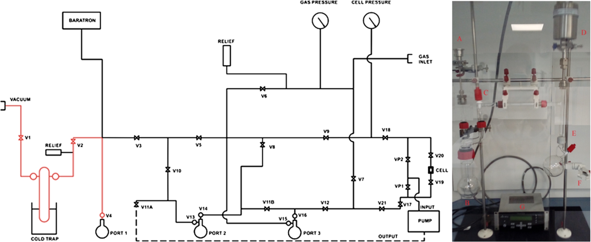
Fig. 1.
(left) Schematic view of the comprehensive liquid handling system for sample deoxygenation and in-situ loading; (right) A simplified Schlenk line designed to handle non-volatile samples prone to cross-contamination.
2.Sample handling
Many applications of Mu chemistry involve either the measurement of systems in solution or the study of solvents themselves. Accordingly, significant work was carried out to optimize equipment for handling the deoxygenation and transfer of liquid samples. The paramagnetic Mu probe species is known to undergo rapid spin exchange on encountering molecular O2 [24], with a rate constant comparable to many of the reactions under investigation. Therefore, it is essential to deoxygenate samples prior to study, and to maintain them in oxygen free conditions throughout the measurements. A dissolved oxygen meter (Hack HQ30D with Intellical LDO101 sensor) was purchased to enable oxygen levels in aqueous samples to be monitored. Provision was also made for handling aggressive samples and thought was given to avoiding cross-contamination of sample materials (a particular problem for non-volatile systems). We therefore designed systems for:
Sample deoxygenation, using either freeze-pump-thaw cycling or by bubbling inert gas. This requirement was developed in two ways. Firstly, a comprehensive liquid handling system was recommissioned (presented in schematic in Fig. 1), providing facilities for sample deoxygenation either using freeze-pump-thaw cycling or bubbling with inert gas, and in-situ loading of a cell connected to the rig with liquid transported either under gas pressure or using a peristaltic pump (Cole Parmer Masterflex L/S with 77200-50 head). This liquid handling system was formed largely from 6.35 mm diameter stainless steel tube, while the three sample vials (labelled ‘Port 1’, ‘2’ and ‘3’ in the diagram) are in glass, with glass to metal seals incorporating silicone O-rings. There was concern, however, that the metal tubing may become contaminated by non-volatile samples, leading to sample cross-contamination, and opening up the possibility of parts of the system being attacked by aggressive samples. Therefore, a simplified all-glass Schlenk link was developed (also shown in Fig. 1) to provide just the key preparation step of freeze-pump-thaw cycling, with samples loaded ex-situ.
Ex-situ sample loading into a sealed holder under inert conditions. This requirement was met by providing an MBRAUN acrylic glove box workstation with an oxygen probe (MB-OX-SE1). An oxygen level of approximately 50ppm can readily be achieved by purging the box with inert gas (typically argon) for about two hours before sample loading. Vials are removed from the rig and taken into the box for transfer to a sealed sample holder. This holder is an all-welded Ti design with a volume of ∼5 cm3; beam enters through a 35 mm diameter 100 μm thick Ti foil window, and a short 3.175 mm diameter Ti capillary allows samples to be loaded using needle and syringe. The capillary is sealed using a Ti Swagelok cap.
In-situ sample loading/unloading. This option was desirable to facilitate rapid sample changing for efficient use of experimental time. Samples prepared on ‘Port 3’ of the metal system can readily be transferred to an evacuated cell at the sample position, provided the sample vial is backfilled with inert gas. Provision was also made for a peristaltic pump, to provide an alternative method for sample loading/unloading, and to allow unstable samples to be continuously circulated. The pump was found to work well for sample handling with the newly developed chemistry insert, but was less successful for moving liquids around the centre stick. In the latter case, major bottlenecks proved to be the extended lengths of relatively narrow 1.5875 mm diameter capillary and the vertical geometry, both imposed by the use of an existing cryostat as sample environment.
3.Centre stick for a 4He flow cryostat with RF muon chemistry capability
3.1.Cell and RF coil development
To allow for Mu chemistry experiments to be run over the widest possible temperature range, an insert was designed for an existing Oxford Instruments 4He flow cryostat, a system compatible with all the ISIS muon spectrometers. The cryostat allows measurements to be carried out over a temperature range 4–400 K, with the sample in a low pressure (∼30 mbar) He exchange gas for effective temperature thermalisation.
The completed cell and RF coil are shown in Fig. 2. For RF compatibility, a non-metallic cell body was required, and both polyether-ether ketone (PEEK) and Shapal ceramic [25] materials were considered. While both could readily be machined to form the cell components, there was awareness that muons stopping in PEEK would form a muoniated radical that could be confused with the sample signal [5]. This is in contrast to Shapal, where only free Mu is measured, and for this reason Shapal ceramic was selected as the material of choice.
A square cell was designed with side 36 mm (for compatibility with the cryostat), and a beam entry window of side 25 mm to ensure an acceptable fraction of incident muons can enter the cell (on EMU approximately 25% of muons in the beam spot fall outside a 20 mm diameter circle). The window was made from Kapton film (thickness 125 μm), made leak tight by gluing to the external frame (using Stycast 2850FT adhesive) before fixing the external ring with Shapal screws. The overall volume of the cell was ∼1.2 cm3.
Fig. 2.
(left) The Shapal ceramic cell on the RF muon chemistry centre stick, with an RF coil wound on the cell; (centre) RF measurements at 9.5 MHz of the
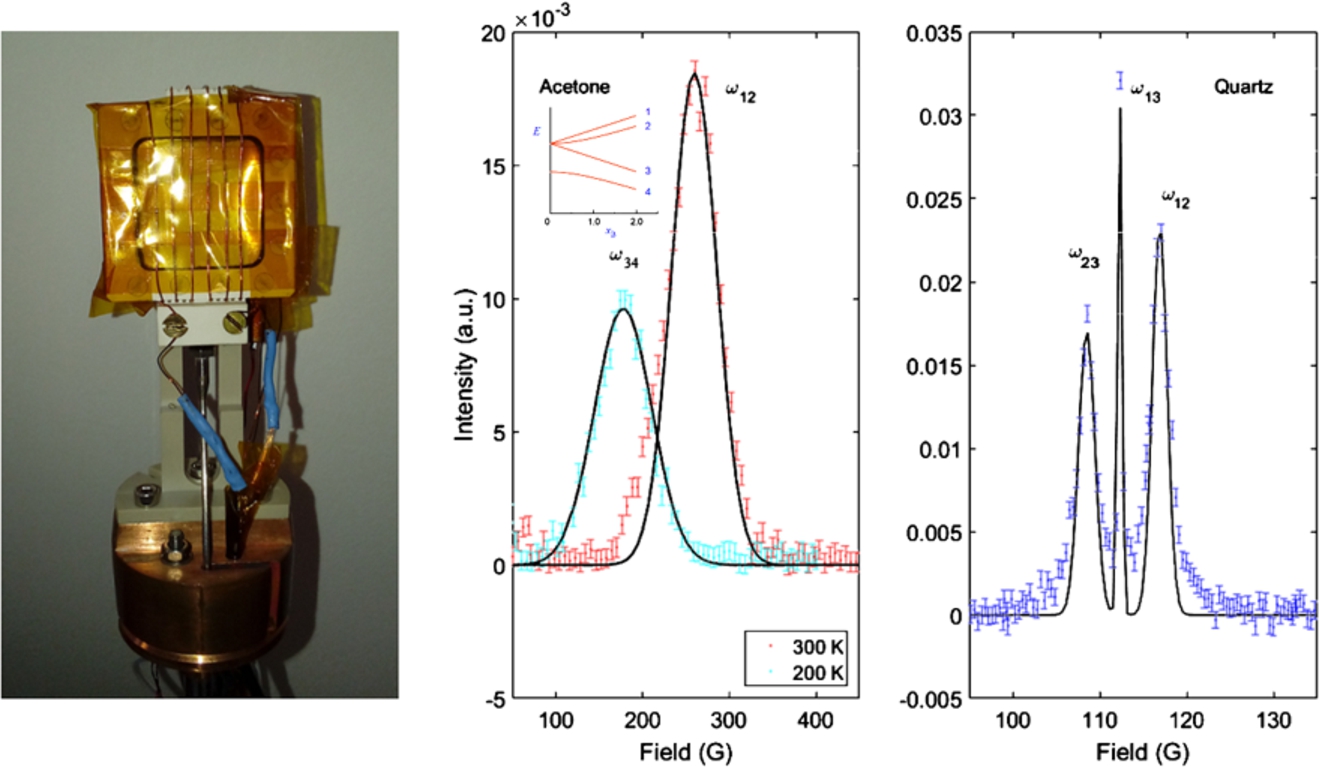
There was concern that samples (particularly solvents) may leach impurities from the adhesive, affecting the measurements being carried out. This was tested for by implanting muons in deoxygenated ethanol and measuring the spin relaxation of the Mu signal (in a 2 G field transverse to the muon spin polarization) over an extended period (at least 12 hours). The form of the signal was found to be invariant with time, and we therefore concluded that samples will be stable in the cell for at least the duration of typical experiments.
A coil was required to generate the RF field, B1, transverse to the static applied field, B0 (itself collinear with the muon beam). A flattened solenoid was used, as shown in Fig. 2, formed from approximately six turns of 28 SWG enameled Cu wire, and the external surface of the body of the cell was engraved to facilitate winding the coil. Compared to a standard NMR setup, RF-μSR introduces additional challenges: large volume coils are required to cover the relatively large sample volume and beam profile (in this case approximately
3.2.Evaluation experiments
Acetone was selected as a suitable test sample as the muon hyperfine coupling of the muon-adduct, the 2-muoxyprop-2-yl radical [13], formed by Mu addition to acetone, is small, giving two significant advantages. Firstly, this allows the resonance condition for the paramagnetic system to be achieved at a relatively low frequency (9.5 MHz in our experiment). A low working frequency simplifies the electrical design of the RF circuit, while allowing the performance of the RF coil to be easily characterised by measuring muons thermalized into the diamagnetic state in acetone. Secondly, avoided level crossing data could be obtained simultaneously in the field range available on the EMU spectrometer. This type of measurement scheme potentially offers a unique view of this muoniated system, allowing muon and nuclear hyperfine parameters to be determined under identical conditions. The outcome of these measurements will be reported in detail in a later publication.
High purity (>99.9%) acetone was deoxygenated on ‘Port 3’ of the liquid handling system and loaded in-situ into the sample cell. The RF cavity was tuned and matched to 50 Ω at 9.5 MHz. The condition for resonance with the diamagnetic species is given by the Larmor condition,
Muoniated radicals are formed with a broad range of muon hyperfine couplings, acetone forming one of the lowest, while aromatic systems have some of the highest – the cyclohexadienyl radical formed in benzene, for instance, has a coupling of ∼515 MHz at room temperature [23]. To investigate whether the present solenoidal coil can be tuned and run effectively at the higher frequencies required for the study of these systems, the coil was tuned and matched at 158.5 MHz and a separate experiment carried out using a quartz plate as a test sample. At this frequency, the RF resonance of the diamagnetic muons would occur at a field of ∼1.1 T; this field cannot be accessed on EMU, and therefore the Mu species was studied to characterize the coil. Vacuum state Mu is readily formed in quartz, and the recorded spectrum, shown in Fig. 2, is characteristic of this system. Fitting using Gaussian peak functions determined the positions of the
4.Muon chemistry insert optimized for liquid phase experiments with RF capability
4.1.Insert development
A number of limitations of the chemistry centre stick led to the development of a dedicated muon chemistry insert, specifically optimized for liquid phase muon chemistry experiments. Key design requirements for this new system were as follows. Firstly, for many experiments, a limited temperature range (close to room temperature) is adequate. Secondly, the strong temperature dependence of many hyperfine couplings demands good temperature stability. Thirdly, the ability to load, unload and circulate samples in-situ is important, and changes to the cryostat geometry and liquid circuit were made to improve this aspect of the operation. Fourthly, an enlarged beam window was desirable to make better use of the incident muons. Fifthly, a revised sample and coil geometry was adopted to allow sufficient space to develop a birdcage RF cavity [12]. Finally, a move to running the RF circuits in vacuum (rather than in a low pressure He exchange gas) was desirable to minimize electrical breakdown. An insert was designed to meet these requirements. An exploded CAD drawing of the system is shown together with the assembled insert in Fig. 3.
Fig. 3.
(left) A CAD view of the chemistry insert, showing internal components, and (right) the completed system with the metal cell attached.
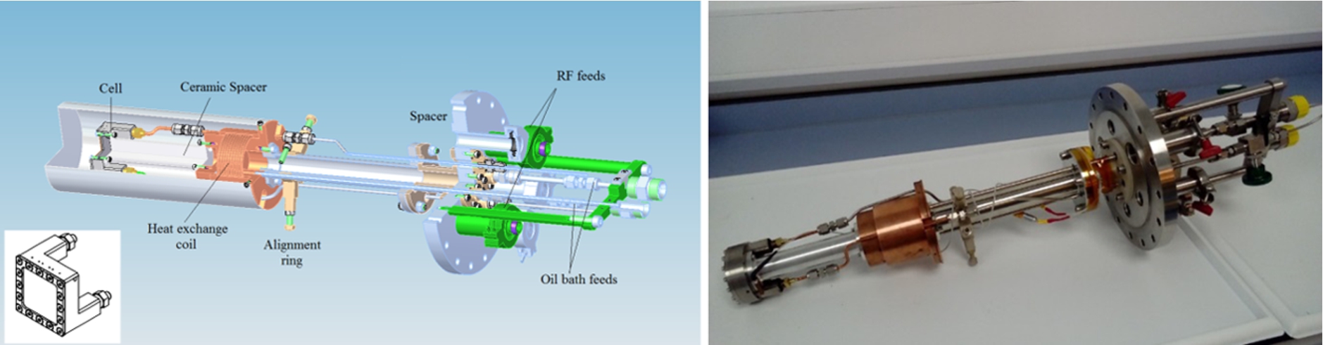
Variable temperature operation was achieved using a Julabo Presto A40 temperature control system. This system covers a temperature range −40°C to +250°C, suitable for many liquid phase measurements. The unit circulates thermostatically controlled oil to regulate the temperature of a copper heat exchanger, which is monitored by a Pt100 thermometer. The sample cell is connected to the heat exchanger by a high thermal conductivity cold finger, made from either aluminium or Shapal ceramic depending on whether RF measurements are intended. The sample liquid circuit is formed from 3.175 mm diameter capillary, designed to be easily removable in case of contamination. Most of the circuit uses stainless steel tube; however, a section that spirals round the heat exchanger uses copper tube to maximize heat transfer. As the peristaltic pump circulates the sample liquid, the spiral thermalises the temperature of the liquid before it reaches the sample holder, minimizing sample temperature perturbations as the liquid circulates. This is particularly important when the sample is continuously circulated during an experiment, and it has previously been demonstrated as an effective solution for this type of sample flow system [29]. This configuration therefore enables measurements to be carried out in two different regimes: firstly, with a static liquid sample, which is achieved by isolating the liquid circuit after filling the sample cell, and secondly, with a liquid sample under continuous circulation. While the former case covers the majority of Mu chemistry experiments, the latter is suitable for experiments on liquid materials that are either degraded by their environment or for liquids undergoing chemical reactions. In either case, the cell can readily be emptied using the peristaltic pump in preparation for a sample change.
4.2.Sample holders
At an early stage in the design, it was realized that an option to run either a metallic or non-metallic cell on the insert would be advantageous. In order to use ceramic parts, components such as the windows and the liquid feeds have to be glued, and, following from this, there’s a need to establish that no interaction occurs between the glue and the liquid sample. Metal-based components offer multiple advantages: they are stronger, easier to maintain and handle, and they are compatible with a wider range of sample materials. Metal components do not allow RF-μSR experiments, but they ultimately provide a simple alternative that is suitable for many muon spin relaxation or avoided level crossing measurements. Accordingly, both metal and ceramic cells were developed, and these are shown in Fig. 4.
Fig. 4.
Liquid sample holders for Mu chemistry experiments manufactured from Shapal ceramic (left) and titanium. The holders are designed for the RF chemistry insert. The ceramic cell has provision for an RF coil for resonance experiments.
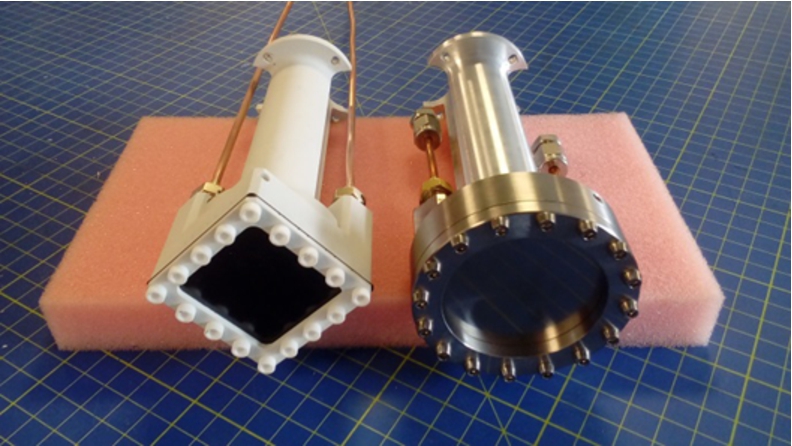
The metal cell consisted of a body made from high purity titanium (>99.6%), with a clamped 100 μm thick titanium foil beam window sealed using a Viton O-ring (chosen for its resistance to commonly used solvents). The body of the cell was brazed with brass inserts to provide two 3.175 mm diameter capillaries to complete the liquid circuit. The temperature was monitored using a Pt100 thermometer, the sensor attached to the cell body to ensure an accurate representation of the sample temperature.
The design of a ceramic sample cell for the new chemistry insert was similar to that described for the chemistry centre stick. However, advantaged was taken of the new system geometry to increase the cell size (to side 50 mm), this increase allowing a larger beam window to minimize the fraction of muons implanted into the cell walls. The increase in cell dimensions required a thicker window for strength, and 500 μm Kapton was used in this case. The overall volume of the cell was increased to ∼2.4 cm3. For proper circulation of the sample, two 3.175 mm diameter capillaries were provided at the top and bottom of the cell. The temperature was monitored using a Pt100 thermometer. As before, provision was made for a flattened solenoid RF coil, and this required the cell to be square rather than copying the circular metal design.
4.3.Insert and cell commissioning
For both cells, tests were carried out in the manner previously discussed to confirm that samples remained clean for the duration of typical experiments.
The size of the cell window is a major factor in determining the efficiency with which experimental data can be collected. For a smaller window, muons are implanted in both sample and cell, reducing the amplitude of the sample signal. In contrast, a larger window allows almost all incident muons to be implanted into the sample, giving the largest possible relevant signal. To investigate cell efficiency and compare data quality, each cell was filled each with deoxygenated water and the amplitude of the Mu spin precession measured in a 2 G field transverse to the muon spin polarization. Based on these data, a figure of merit (FoM) was defined as in Eq. (1):
Values were normalized with respect to the FoM obtained from a measurement in the Shapal cell used in the chemistry centre stick, essentially using it as a benchmark for the evaluation of the new cells shown in Fig. 4. Values for the FoM for the metal and ceramic cells were determined to be 1.7 and 1.6 respectively, demonstrating a considerable improvement compared to the original cell. We believe this gain is mainly due to the larger beam windows of the new cells, allowing effective use of all incident muons. Further improvement should be possible through a reduction of the beam collimation – the large window allows the collimation slits to be opened for higher data rates whilst still maintaining close to 100% stops in the sample.
Fig. 5.
(left) Transverse 2 G Mu spin relaxation signals measured in a 0.14 mmol solution of maleic acid at 5°C (blue) and 70°C (red), the relaxation rate allows the reaction rate constant,
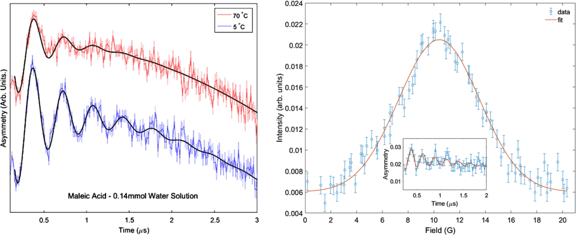
To complete the commissioning of the system, the reaction rate constant corresponding to the addition of Mu to an organic compound was measured and compared to the literature value. This is a typical application of the sample environment, and therefore provides a good demonstration of the utility of the insert for Mu chemistry experiments. An aqueous solution of maleic acid, at a concentration of 0.14 mmol, was deoxygenated by bubbling nitrogen gas, and loaded into the metal cell. Reaction kinetics of the system were studied by measuring the Mu spin relaxation rate,
A pseudo first-order reaction (
The relaxation,
Fitting Eq. (2) to the data collected at 25°C allowed
4.4.Commissioning the RF cavity
The ceramic cell equipped with a flattened solenoid was used to generate the RF field required for resonance experiments, with the coil being formed from approximately six turns of 28 SWG enameled Cu wire, with an overall length of ∼35 mm. The coil was tuned and matched to 50 Ω at a frequency of 15.145 MHz. The performance of the coil was evaluated by measuring the
5.Birdcage RF cavity
The simplest experimental setup to generate the time-varying magnetic fields required for RF resonance experiments is the flattened solenoid. This design of cavity has a number of advantages, including being easy to tune and match, compact, and readily capable of producing the large B1 fields required for the RF-μSR experiment. Unfortunately, there are also disadvantages to this design, such as the coil windings crossing the beam entry window, limited field homogeneity, and difficulties tuning and matching the coil at higher frequencies (typically above ∼60 MHz) that are often required for resonance studies of muoniated radicals. The field homogeneity is frequently compromised by the need to work with comparatively large misshapen solenoids to match the beam geometry, while the large inductance (arising from multiple turns and a large overall volume) creates a coil with a high frequency impedance that can be difficult to tune and match to 50 Ω using standard circuits. Alternative coil designs have therefore been investigated with the aim of extending the capabilities of resonance experiments.
There are many designs of RF cavity in the literature that have been developed with the express purpose of enabling high working frequencies, while providing good field homogeneity over a large volume. The medical imaging community, in particular, commonly exploits complex designs, such as birdcage and TER coils, for a range of applications in the field of magnetic resonance imaging (see, for instance, the review by Hayes [12]), and therefore these are particularly suited to measuring over large volumes.
The geometry of birdcage coils appears ideal for RF-μSR. The coil is composed of two end-rings, usually circular in shape, connected by a variable number of equally spaced legs. Equivalent capacitors are included either on the legs or the end-rings (between adjacent legs), the configuration determining whether the coil operates in low-pass or high-pass mode, respectively. When energized, a circularly polarized RF field is setup, perpendicular to the long axis of the coil. Thus, the coil can be orientated such that the beam can enter through the open end created by the end-ring, to stop in a sample cell positioned at the coil centre. The utility of the birdcage coil for Mu chemistry RF-μSR experiments was previously recognized by Sun-Mack [27], and we have sought to adapt this design of cavity to work within the newly developed chemistry insert.
Fig. 6.
Prototype birdcage coil mounted in the RF cryostat. The ceramic liquid cell is visible through the polythene coil former.
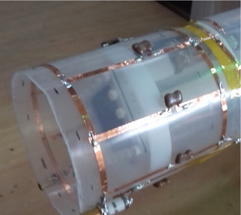
The coil was designed as low-pass resonator, using published [15] and on-line [2] resources to achieve an eight-leg electrical design capable of running at ∼150 MHz. For the prototype shown in Fig. 6, the coil was constructed on a polythene former of diameter 80 mm and length 80 mm.
Adhesive Cu foil tape was used to create the conductive end-rings and rungs, with 10 pF silvered mica capacitors providing the fixed capacitance required to achieve the desired operating frequency. For optimal field distribution inside the coil, a quadrature-driven resonator was used, with a high-power RF splitter (Werlatone QH10882-10, 2 way 90° Hybrid Coupler) providing two electrical feeds, each independently matched to 50 Ω impedance using an additional series 1–40 pF variable capacitor (Voltronics AT40HV) for optimal power transfer. A cylindrical shield was provided outside the birdcage, and grounded to the screen of the RF feed (as suggested by Liu [16]) for optimal field homogeneity. The final working frequency of the coil was 151.45 MHz.
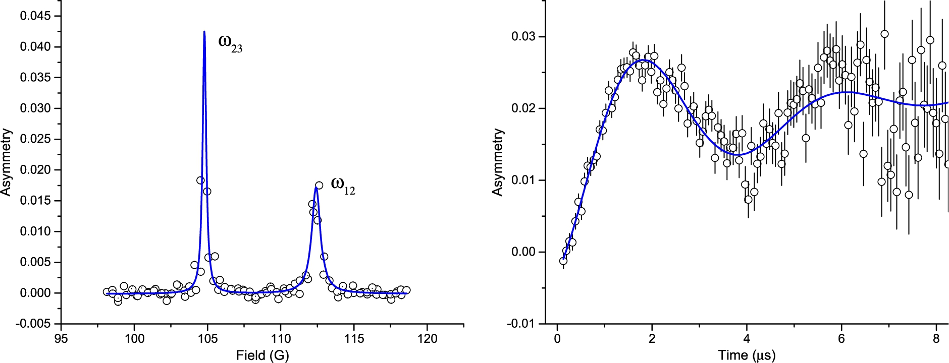
The performance of the coil was evaluated by studying Mu formed in a fused quartz plate, placed on the window of the ceramic cell mounted in the chemistry insert. A swept field measurement, carried out with an RF input power of 100 W, clearly defined the two lines corresponding to the
Fig. 7.
(left) A swept field measurement defines the two lines corresponding to the
6.Conclusions and future work
Work during this project has provided the ISIS muon source with a comprehensive suite of sample environment equipment for efficient running of muon chemistry experiments over a wide range of conditions. The chemistry centre stick enables experiments to be carried out to liquid helium temperatures in a 4He flow cryostat, while the chemistry insert provides optimal conditions for liquid state measurements carried out close to room temperature. RF-μSR measurements are possible over a wide temperature range, with the RF circuits working across a broad frequency range, enabling the study of muoniated radicals with a wide range of hyperfine parameters. In-situ sample loading is possible in both systems, while sample unloading and the option for continuous sample flow works well in the dedicated insert owing both to a change of geometry and reduced impedence of the liquid circuit. Off-beam sample preparation equipment has been improved, allowing users to prepare samples with good reliability. All equipment is now in regular use within the ISIS muon user programme.
Although much has been achieved through this project, there are still aspects of the equipment where further development would be beneficial. The overall design of the chemistry insert has proved very effective, enabling measurements to be carried out with much greater efficiency, with a geometry providing much improved access both for sample cells and RF cavities. We therefore hope to make a N2 flow version of this system to provide an extended operating temperature range, allowing more experiments to benefit from this improved design. While the birdcage coil provides a reliable means of carrying out high frequency RF measurements, the overall RF field strength is compromised at present by the large volume required to contain the existing ceramic cell. We therefore plan a redesigned cell, circular in shape, allowing us to revise the design of the birdcage, reducing the volume to greatly improve the RF field strength (noting that B1 α volume
Acknowledgements
The authors wish to thank Colin Offer of the ISIS Instrument Design group for engineering support developing the cells, and the ISIS Sample Environment group for experiment support.
 The work described was performed as part of the world class Science and Innovation with Neutrons in Europe 2020 (“SINE2020”) project, which was funded from the European Union’s Horizon 2020 research and innovation programme under grant agreement No.°654000.
References
[1] | O. Arnold, J.C. Bilheux, J.M. Borreguero, A. Buts, S.I. Campbell, L. Chapon, M. Doucet, N. Draper, R. Ferraz Leal, M.A. Gigg, V.E. Lynch, A. Markvardsen, D.J. Mikkelson, R.L. Mikkelson, R. Miller, K. Palmen, P. Parker, G. Passos, T.G. Perring, P.F. Peterson, S. Ren, M.A. Reuter, A.T. Savici, J.W. Taylor, R.J. Taylor, R. Tolchenov, W. Zhou and J. Zikovsky, Nuclear Instruments and Methods in Physics Research A 764: ((2014) ), 156. doi:10.1016/j.nima.2014.07.029. |
[2] | Birdcage Builder Java web app, Penn State College of Medicine, see https://research.med.psu.edu/departments/center-for-nmr-research/software/birdcage-builder-web-app/. |
[3] | G. Breit and I.I. Rabi, Phys. Rev. 38: ((1931) ), 2082. doi:10.1103/PhysRev.38.2082.2. |
[4] | D. Buttar, R.M. Macrae, B.C. Webster and E. Roduner, Hyperfine Int. 65: ((1990) ), 927. doi:10.1007/BF02397744. |
[5] | L. Chandrasena, I. McKenzie, J.-C. Brodovitch, M. Mozafari, S.P. Cottrell and P.W. Percival, J. Phys. Conf. Ser. 551: ((2014) ), 012038. doi:10.1088/1742-6596/551/1/012038. |
[6] | S.P. Cottrell, S.F.J. Cox, J.S. Lord and C.A. Scott, Applied Magnetic Resonance 15: ((1998) ), 469. doi:10.1007/BF03162029. |
[7] | S.P. Cottrell, S.F.J. Cox, C.A. Scott and J.S. Lord, Appl. Physica B 289–290: ((2000) ), 693. doi:10.1016/S0921-4526(00)00314-8. |
[8] | U.C. Dawin, H. Dilger, E. Roduner, R. Scheuermann, A. Stoykov and F. Giesselmann, Angew. Chem., Int. Ed. 49: ((2010) ), 2427. doi:10.1002/anie.200904107. |
[9] | D.G. Fleming, S.P. Cottrell, I. McKenzie and K. Ghandi, Phys. Chem. Chem. Phys. 17: ((2015) ), 19901. doi:10.1039/C5CP02576A. |
[10] | E. Fukushima and S.B.W. Roeder, Experimental Pulse NMR, Addison-Wesley, (1981) . |
[11] | S.R. Giblin, S.P. Cottrell, P.J.C. King, S. Tomlinson, S.J.S. Jago, L.J. Randall, M.J. Roberts, J. Norris, S. Howarth, Q.B. Mutamba, N.J. Rhodes and F.A. Akeroyd, Nuclear Instruments and Methods in Physics Research A 751: ((2014) ), 70. doi:10.1016/j.nima.2014.03.010. |
[12] | C.E. Hayes, NMR in Biomed. 22: ((2009) ), 908. doi:10.1002/nbm.1431. |
[13] | A. Hill, M.C.R. Symons, S.F.J. Cox, R. De Renzi, C.A. Scott, C. Bucci and A. Vecli, J. Chem. Soc. Faraday Trans. 1: (81) ((1985) ), 433. doi:10.1039/f19858100433. |
[14] | S.R. Kreitzman, Hyperfine Int. 65: ((1990) ), 1055. doi:10.1007/BF02397762. |
[15] | M.C. Leifer, J. Magn. Res. 124: ((1997) ), 51. doi:10.1006/jmre.1996.7488. |
[16] | W. Liu, S. Zang, C.M. Collins, J. Wang and M.B. Smith, Comparison of four different shields for birdcage-type coils with experiments and numerical calculations, Concepts Magn. Reson. Part B Magn. Reson. Eng. 29B: (4) ((2006) ), 176. |
[17] | A. Martyniak, H. Dilger, I. McKenzie, R. Scheuermann and J. Lagerwell, Colloids Surfaces A 309: ((2007) ), 224. doi:10.1016/j.colsurfa.2006.10.068. |
[18] | I. McKenzie, Annu. Rep. Prog. Chem., Sect. C: Phys. Chem. 109: ((2013) ), 65. doi:10.1039/c3pc90005c. |
[19] | I. McKenzie, R. Scheuermann, S.P. Cottrell, J.S. Lord and I.M. Tucker, J. Phys. Chem. B 117: ((2013) ), 13614. doi:10.1021/jp4068763. |
[20] | P.W. Percival, Radiochimica Acta 26: ((1979) ), 1–14. doi:10.1524/ract.1979.26.1.1. |
[21] | C.J. Rhodes, Annu. Rep. Prog. Chem., Sect. C: Phys. Chem. 107: ((2011) ), 47. doi:10.1039/c1pc90002a. |
[22] | E. Roduner, Chem. Soc. Rev. 22: ((1993) ), 337. doi:10.1039/cs9932200337. |
[23] | E. Roduner, P.W. Percival, D.G. Fleming, J. Huchmann and H. Fischer, Chem. Phys. Lett. 57: ((1978) ), 38. |
[24] | E. Roduner, P.L.W. Trehenna-Piggott, H. Dilger, K. Ehrensberger and M. Senba, J. Chem. Soc. Faraday Trans. 91: ((1995) ), 1935. doi:10.1039/ft9959101935. |
[25] | |
[26] | C.P. Slichter, Principles of Magnetic Resonance, Springer-Verlag, (1990) . |
[27] | S. Sun-Mack, Delayed formation and intramolecular motion of muonium-substituted free radicals, PhD thesis, Simon Fraser University. |
[28] | D.C. Walker, Muon and Muonium Chemistry, Cambridge University Press, (2009) . |
[29] | K. Yokoyama, J.S. Lord, P. Murahari, K. Wang, D.J. Dunstan, S.P. Waller, D.J. McPhail, A.D. Hillier, J. Henson, M.R. Harper, P. Heathcote and A.J. Drew, Rev. Sci. Instr. 87: ((2016) ), 125111. doi:10.1063/1.4972827. |


