
Huginn: A Peltier-based sub-cryostat for neutron scattering
Abstract
A longstanding problem in facility based experiments is the time one must wait whilst changing sample temperature. This issue is most often confronted at cryogenic temperatures above 100 K, where thermal response times can be very slow. These can be drastically reduced by minimising the amount of material being controlled to as little as possible beyond the sample itself. Peltier elements provide an effective way to achieve this, but are mostly used to regulate with respect to room temperature. We report on the Huginn sub-cryostat, a cryostat insert with dual Peltier regulation, useable down to 100 K, that enables large and rapid temperature jumps of up of 10 K to 20 K in minutes or less. Moreover, temperature stability is improved by an order of magnitude in the presence of a variable background temperature.
1.Introduction
A significant amount of valuable measurement time is lost while waiting for sample temperatures to equilibrate after a change of temperature set-point. This is particularly true in the temperature range between room temperature and down to 100 K, where many common cryostat construction materials have large specific heat capacities and low thermal conductivities. Controlling the temperature of a sample with a minimum of additional material within a larger cryostat is therefore a promising route to considerable time savings. Peltier elements have many advantages for achieving this over simple resistive heating on a weakly linked sample holder. They allow for fast cooling as well as heating of small items. This can be achieved without relying on the cooling power of an outer cryostat, which must often be transmitted through a relatively long thermal path to the sample itself, and also cool other parts of the cryostat. However, performance is limited by the temperature dependent thermoelectric power of the elements, and their coupling to the environment to get rid of waste heat. Peltier elements are often used for temperature regulation around room temperature (see for example [1]).
Fast and accurate temperature control is crucial for many research fields, especially for the fast growing community of soft condensed matter (see e.g. the ESS TDR [2], Chapter 2.2.1). Beside optimising the use of neutron beam-time by decreasing equilibration time, fast temperature jumps also open new scientific possibilities. With the availability of rapid temperature changes, time-resolved physical ageing experiments and studies of phase transformation kinetics after a temperature jump can be performed in much shorter time, making it possible to take advantage of the increased neutron flux at high-power facilities such as ESS. Fast temperature jumps will also assist with the study of new metastable states of materials (see e.g. [3] for an example of a similar development in scanning microcalorimetry using high cooling rates).
The basis for the Huginn11 collaborative project between ESS and Roskilde University is an existing Peltier based sub-cryostat design [4] developed at Roskilde University for research into physical ageing of glass-forming liquids [5–7]. The Huginn project consists of the construction of two different types of Peltier-controlled platforms:
A sub-cryostat insert for closed cycle and top loading variable temperature environments for use with general purpose sample holders. This is a modular device, based on Peltier elements. It can be used both in connection with (i) existing low temperature cryostats and (ii) using only a simple external cooling/heating device for work at around room temperature.
A Small Angle Neutron Scattering (SANS) multi-temperature sample rack. This is a cuvette holder in a SANS geometry which can simultaneously control the individual temperatures of up to 5 samples, over a moderate temperature range around a base temperature near room temperature. This device will enable a fast change between different temperatures during an experiment, by changing which sample is investigated.
2.Requirements and challenges
In this section we give an overview of the performance criteria, the physical limitations, and technical challenges that lay the background for our design choices.
2.1.Thermal criteria
Improved temperature stability compared to conventional cryostats. Absolute temperature can be determined using platinum thermometers to
Fast small temperature jumps. Temperature jumps of order of ±5 K are expected to be in equilibrium within few minutes. Limiting factors are the diffusion constant of the holder and sample, as well as acceptable temperature overshoot.
Large temperature jumps using only the sub-cryostat. Temperature differences from the main cryostat of at least 10 K to 20 K should be obtainable. The maximum size of jumps are determined by the required equilibration time (and selected Peltier element), as Peltier elements in general have lower thermal power at large temperature differences, and therefore a slower cooling/heating rate.
The sub-cryostat must not be harmed by being cycled to the base temperature of a normal cryostat.
2.2.Mechanical criteria
The overall mechanical design aim is to develop as flexible as possible a sub-cryostat.
The sub-cryostat is connected to the main cryostat with a simple M8 thread.
The size of the sub-cryostat is chosen to fit existing cryostats, including use with a vacuum stick for a standard orange-cryostat.
The interface between the sub-cryostat and the sample holder or mounting plate is as simple as possible. In the following we term the generic connector part of the sub-cryostat the ‘sample connector’. For each type of sample a specific ‘sample holder’ needs to be developed, fitting to the sample connector of the sub-cryostat. This can be as simple as a rectangular aluminium plate.
2.3.General challenges
The maximum rate of cooling or heating is given by the thermal diffusion in the sample/sample holder, controlled by its heat capacity, thermal conduction and geometry. This can be partly overcome by low mass sample holders and good connection to the sample connector of the sub-cryostat.
Often one cannot live with an overshoot in temperature in parts of the sample, and therefore the flexibility in control algorithms is limited. The best we can do in this case is to achieve the desired temperature at the boundary of the sample and wait.
To transport heat we need thermal contact – but whatever transports heat will also scatter. We want to get the heating/cooling source as close to the sample as possible without getting too much material in the beam.
The temperature difference a Peltier element can sustain and its ‘pumping power’ are limited by the ohmic self heating of the element. The amount of heat pumped by the Peltier element is linear in the electrical current, whereas the ohmic heat generation is quadratic in the current. Eventually the element generates more ohmic heat than it is able to pump away. The Peltier coefficient is highly temperature dependent, limiting the efficiency at low temperatures.
The pumped and generated heat needs to be transported from the ‘back’ of the Peltier element, which is thermally connected to the main cryostat. This process is limited by diffusion and therefore rather slow. Heat is mostly produced when temperature jumps are performed, the problem is therefore highly dynamical and can partly be solved by optimisation of temperature regulation protocols.
3.Mechanical design
Fig. 1.
(a) Annotated drawing of the Huginn sub-cryostat, the different main parts are indicated with different colours. Notice the positions of the three thermometers, two on the sample connectors and one on the C-shaped main mechanical part of the sub-cryostat. The former (
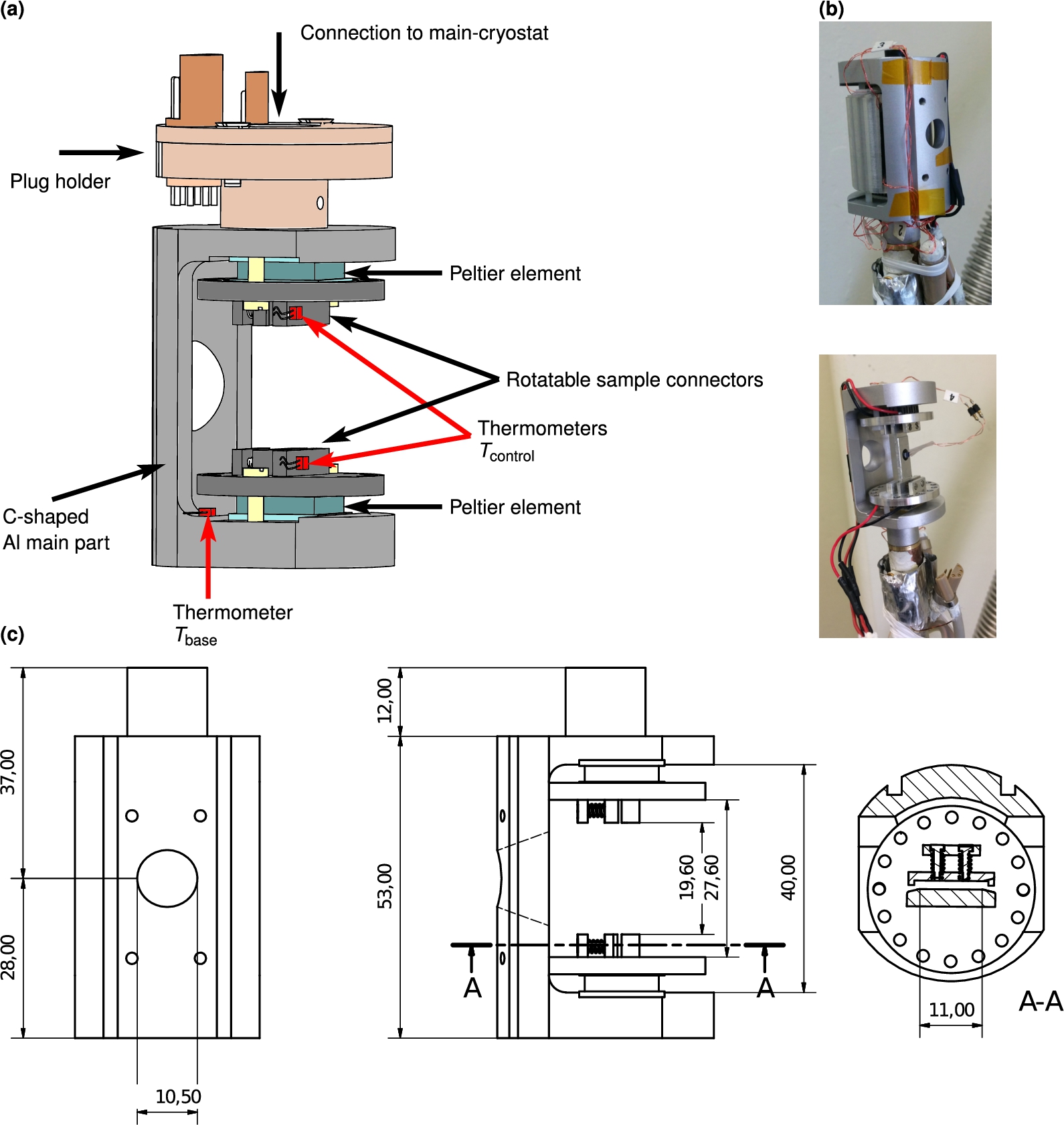
The overall concept of the Huginn sub-cryostat is to control the sample temperature by two individually controlled Peltier elements [8] (see Fig. 1) which are placed at each end of the sample. The temperature is regulated on two sample connectors which are in direct contact with the Peltier elements. The sample holder is then mounted on the sample connectors, which can be oriented as required about an axis perpendicular to the elements. By using two Peltier elements and controlling the temperature of both ends of the sample holder, thermal gradients are minimised, and thermal power maximised. The disadvantage of having two Peltier elements is the need for a mechanical support around the sample, through which the plane containing the beam path inevitably passes.
The two Peltier elements are connected to the main cryostat through the main mechanical part of the sub-cryostat. This is a C-shaped aluminium piece, which in the final version is machined out of one piece of metal to minimise thermal resistance. Aluminium is used to minimise neutron scatter. A hole is provided for the beam and it is possible to mount a neutron absorbing mask on the part facing the neutron beam. This design is suitable for amorphous and polycrystalline samples, or single crystals held in a fixed orientation, as the beam direction is restricted to the hole in the C-piece in a forward scattering configuration. One would expect to follow selected Bragg peaks as a function of temperature in this configuration. More flexibility in orientation may be required, for example due to a peak passing out of the useful range during a measurement. In this case, one can rotate by
The part that connects to the Peltier element furthest away from the main cryostat is made thicker, providing a reservoir to buffer heat pulses when the sub-cryostat is pumping at high power. This improves the performance at low temperatures where the Peltier efficiency is low, and the heat output therefore large.
Two prototypes were made. First, a proof of concept sub-cryostat which is compatible with existing cryostats at Roskilde University [4]. This first version did not have individual control of the two Peltier elements. Test of the first prototype demonstrated that the Peltier elements worked down to the required lowest temperature of 100 K, and provided a convenient test platform for experimenting with control protocols incorporating both the sub- and main cryostats. In the second prototype the thermal link design was refined and the control concept using two independent control loops tested. The final design is made to be compatible with existing closed cycle cryostat (CCR) systems and Orange cryostats, and the sample connector system has been finalised. The final sub-cryostat is also equipped with a removable heat shield to minimise influence from thermal radiation from the sample to the main cryostat. Figure 1 shows the final sub-cryostat.
4.Electronics and control
Due to the difference in thermal impedance between the individual Peltier elements and the main cryostat, two PID control loops are needed for precise control. The thermometers for the PID loops are positioned on the sample connectors, close to the Peltier elements for fast control (see Fig. 1). We refer to the temperature of these thermometers as
One additional thermometer is mounted on the C-shaped main part, measuring the temperature close to the ‘back’ side of the Peltier element further away from the main cryostat (see Fig. 1). We refer to the temperature of this thermometer as
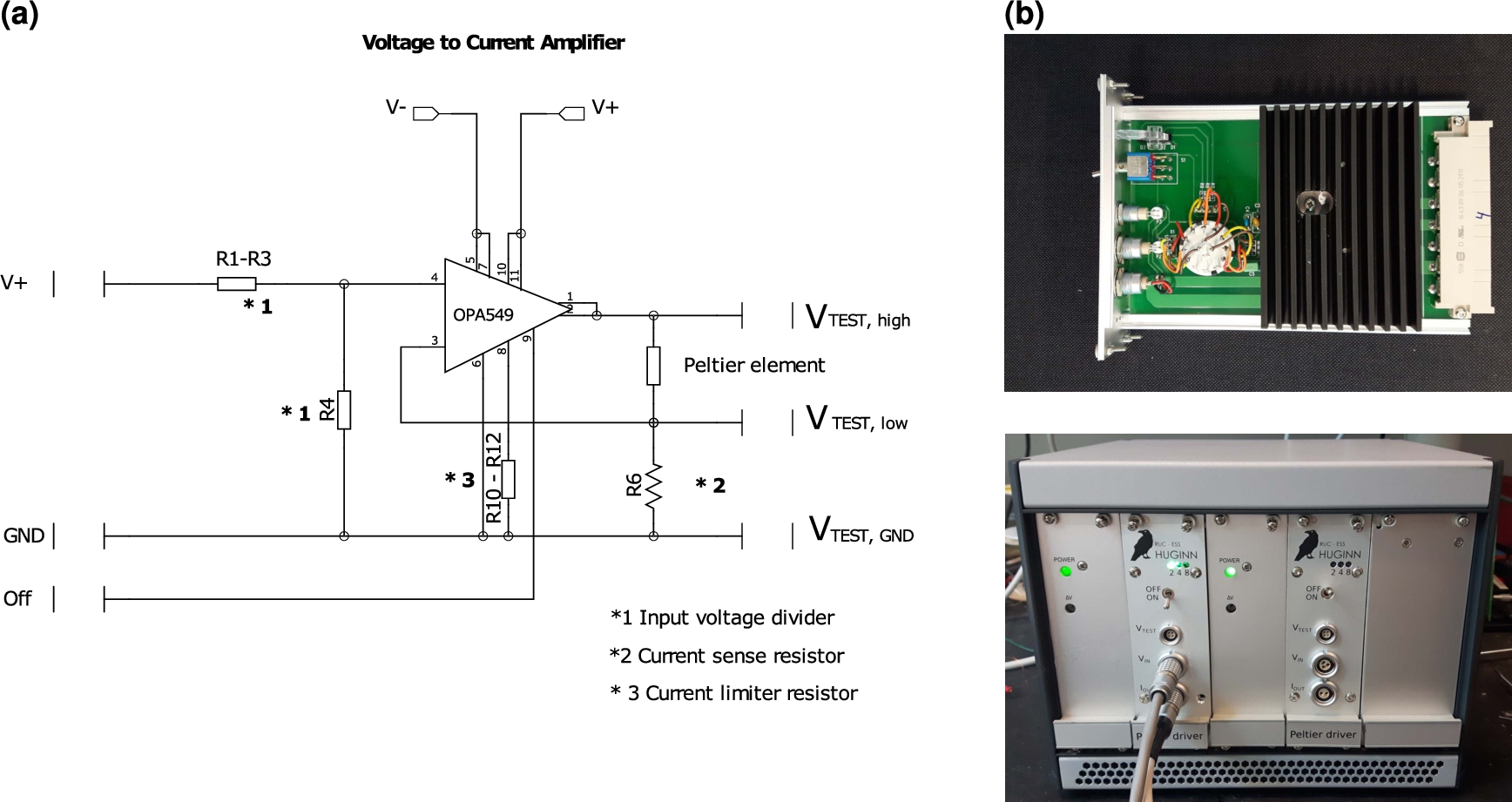
Due to the absence of commercial alternatives, a current amplifier module was designed (see Fig. 2). This transforms the analogue control voltage output from the temperature controller to current, in order to drive the Peltier elements. It is a purely analogue system, and does not use pulse-width modulation. The module is a flexible voltage controlled bi-directional DC current supply. The maximum current can be selected to be
Software control was provided using a combination of EPICS and Matlab, enabling remote operation with a graphical user interface and logging of temperature histories on all channels. The software framework allows for integrated control of the sub-cryostat and the main cryostat, in order to automate the temperature control of the entire system.
Fig. 2.
(a) Schematic diagram of the Huginn Peltier driver module. The diagram shows the voltage divider (R1–R3 and R4) for selecting max current, the Op Amp with feedback ‘current sensing power resistor’ (R6) (providing feedback to the negative input of the Op Amp of 0.1 Volt per Ampere), Peltier module, resistor for utilising the current limiting feature of the OPA549 (R10–R12) and connections for monitoring voltage over the Peltier element and sense resistor (VTEST,high and VTEST,low). When selecting the maximum current output one of the resistors R1–R3 and likewise R10–R12 are selected. (b) Photo of Huginn Peltier driver card, and two channel Peltier driver system for the Huginn sub-cryostat.
5.Performance
The performance of the sub-cryostat depends on the temperature of the main cryostat as well as the chosen temperature protocol. In the following section, we show data from a range of different situations and demonstrate that the performance criteria in Section 2.1 are met.
The sub-cryostat allows the temperature on the sample connector to be maintained at a steady temperature while the main cryostat ramps in the background. Figure 3(a) shows how that works in the case of coarse and fine steps in temperature. In the former case the Peltier elements can only be used once the main cryostat temperature is within a suitable range of the target. Such protocols will allow isothermal measurements to be performed for a much larger part of the total experimental time than is possible with a conventional cryostat. The Peltier regulation also enables large variations in the background temperature (such as from cooling water) to be actively damped to within the resolution of the Lakeshore 336 temperature controller as shown on Fig. 3(b). The data shown in Fig. 3 have been obtained with prototype one, used with a liquid nitrogen cooled cryostat at Roskilde University, and prototype two, with a simple refrigerated/heating water circulator. In both cases the sub-cryostat was under vacuum. Different prototype versions of the control electronics were used.
Fig. 3.
Proof of concept data from the two sub-cryostat prototypes. Sample temperature data are measured on a aluminium dummy sample with a thermometer mounted at the centre. (a) Examples of two protocols for combined use of the main- and sub-cryostat. The main cryostat is a liquid nitrogen cooled cryostat at Roskilde University [4], the sub-cryostat is under vacuum. In the upper part of the main plot the set-point of the main cryostat is continuously changed, and the sub-cryostat automatically turn on and goes to the desired temperatures when the target temperature is within the temperature difference from the base temperature that the Peltier elements are able to sustain. The figure shows the sample temperature both for the parts where the sub-cryostat is off and on. The part of the curve where the sample temperature is in equilibrium is highlighted (defined as a sample temperature within 0.02 K of the target temperature). In the lower part of the plot the set-point temperatures of the main- and sub-cryostat are changed simultaneously. Below the main figure two zooms from the figures above are shown, focusing on a single temperature jump from each protocol. (b) Demonstration of the stability of the sample temperature on the sub-cryostat when using a rather unstable main cryostat, in this case a refrigerated/heating water circulator connected to the sub-cryostat (which is under vacuum) through a heat exchanger.
![Proof of concept data from the two sub-cryostat prototypes. Sample temperature data are measured on a aluminium dummy sample with a thermometer mounted at the centre. (a) Examples of two protocols for combined use of the main- and sub-cryostat. The main cryostat is a liquid nitrogen cooled cryostat at Roskilde University [4], the sub-cryostat is under vacuum. In the upper part of the main plot the set-point of the main cryostat is continuously changed, and the sub-cryostat automatically turn on and goes to the desired temperatures when the target temperature is within the temperature difference from the base temperature that the Peltier elements are able to sustain. The figure shows the sample temperature both for the parts where the sub-cryostat is off and on. The part of the curve where the sample temperature is in equilibrium is highlighted (defined as a sample temperature within 0.02 K of the target temperature). In the lower part of the plot the set-point temperatures of the main- and sub-cryostat are changed simultaneously. Below the main figure two zooms from the figures above are shown, focusing on a single temperature jump from each protocol. (b) Demonstration of the stability of the sample temperature on the sub-cryostat when using a rather unstable main cryostat, in this case a refrigerated/heating water circulator connected to the sub-cryostat (which is under vacuum) through a heat exchanger.](https://ip.ios.semcs.net:443/media/jnr/2019/21-1-2/jnr-21-1-2-jnr180093/jnr-21-jnr180093-g003.jpg)
Figure 4 shows performance from the final design of the sub-cryostat (as shown in Fig. 1) with a base temperature regulated at 250 K. The sub-cryostat was mounted inside a CCR under vacuum and connected to the cold finger via an M8 bolt. This thermal link to the outer cryostat is crucial for the performance of the sub-cryostat, as waste heat must be conducted away at a high enough rate. Tests show that jumps up to 20 K from base temperature are feasible with a base temperature of 250 K. The ‘sample’ shown is an aluminium plate with a thermometer attached. The real performance with an arbitrary sample will of course depend on the heat capacity and thermal conduction of the sample and sample holder itself.
Fig. 4.
Example of the final Huginn sub-cryostat performance with a base (main cryostat) temperature of 250 K. The sub-cryostat was mounted under vacuum inside a CCR cryostat. Up to
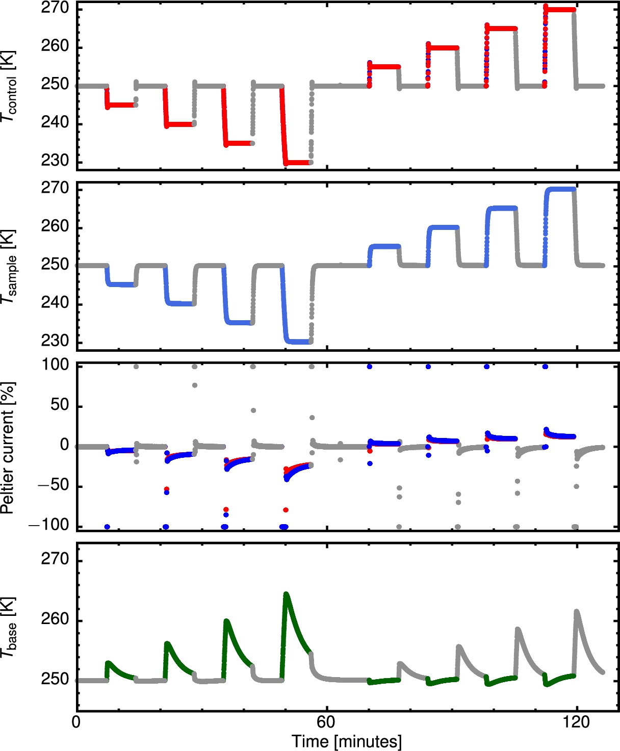
Figure 5(a) shows the limits of the system at the lowest usable temperature of around 100 K. As mentioned earlier the Peltier efficiency decreases with decreasing temperature, limiting the possible temperature differences which the Peltier element can sustain. To reduce ohmic heating effects, we limit the maximum current in the Peltier elements. At 100 K the maximum possible size of temperature steps is around 2 K. Attempts to make larger temperature jumps result in a ‘runaway situation’, where the base temperature increases too much and too quickly to allow for the sample connector to reach the required temperature. This is due to the large ohmic heating and low efficiency of the Peltier element. The exact limits on jump size will depend highly on the thermal connection to the main cryostat and the protocol used on the sub-cryostat. However, the absolute limit with the chosen Peltier elements is a few degrees Kelvin at this low base temperature.
Figure 5(b) demonstrates the ability of the system to compensate for large changes in base temperature. The sample is kept within 0.15 K while the base temperature is swept over a range of
Fig. 5.
(a) Example of low temperature performance of the Huginn sub-cryostat with a base (main cryostat) temperature of 100 K. The sub-cryostat was mounted under vacuum inside a CCR cryostat. For the sample connector temperature and Peltier current, data for both elements are shown. The sample temperature is from a aluminium dummy sample with a thermometer at the centre. As large as 2 K down jumps were performed successfully. In order to obtain this, the maximum current was limited to 1 A, half the normal value, to decrease heat generation from the ohmic resistance in the Peltier element. However, the larger jumps were not successful, as the ohmic heating still dominated the Peltier effect leading to an extensive runaway situation where the increase in base temperature becomes the dominant factor in determining the sample connector temperature. (b) Demonstration of keeping the Sub-cryostat constant at 275 K while changing the main cryostat from 250 K to 300 K. As can be seen the temperature of the sample connector is stable within the noise. The observed change in the sample temperature, which is of the order of 0.15 K (measured at the centre of an aluminium dummy sample) is due to changes in the thermal radiation environment, which is seen to not be totally damped by the radiation shields.
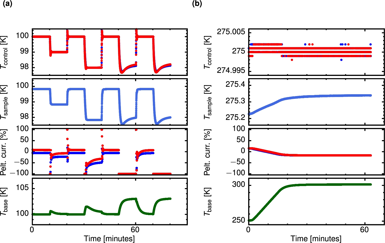
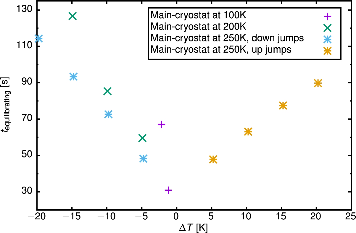
Figure 6 shows the time taken to reach within 0.1 K of the target temperature under various different conditions. All except the most extreme are within 2 minutes. In practise the equilibration time will in most cases be dominated by the thermal properties of the sample and sample holder, showing that the performance of the Huginn sub-cryostat is not the limiting factor. For a given temperature jump size (see e.g. the two jumps of
It is difficult to put a precise value on the maximum jump size as a function of temperature, as it depends crucially on the coupling of the sub-cryostat to the main cryostat, and the cooling power of the latter, along with the temperature dependence of the Peltier efficiency. The setup as demonstrated shows that jumps of 2 K are possible at 100 K, 15 K at 200 K and 20 K at 250 K.
The sub-cryostat was cooled to 15 K within the CCR with no adverse effects, and there is no reason to expect lower base temperatures to cause any damage.
Fig. 6.
Time to reach the final sample temperature to within 0.1 K at different temperature jump sizes (
6.Conclusions
The use of Peltier elements to control the immediate environment around a sample within a larger cryostat has proved successful in a range from 100 K to above room temperature. The goals of 10 K to 20 K jumps within a few minutes, and stability an order of magnitude better than the outer cryostat were met. The final equilibration time will in most cases be determined by the thermal properties of the sample and sample holder.
The system has been tested with a CCR outer cryostat, and is highly suitable for such a setup. With the use of an evacuated can type sample stick, it can be easily adapted for use in a top loading variable temperature insert (VTI) type system. In that case the sub-cryostat would be kept in vacuum but the residual heat from the Peltier elements is removed by heat exchange with the VTI exchange gas. As the cooling power of wet VTI systems are in general much larger than that of a CCR there should be no loss in performance. For a top loading CCR based system where the sample stick is cooled indirectly via exchange gas, the performance will depend on the efficiency of the heat exchange and the cooling power of the outer cryostat. With judicious addition of thermal mass to the Peltier support, the fast temperature jumps (and hence favourable measurement duty cycle) can be maintained, at the expense of a longer time between temperature changes. In addition, the system is compatible with a simple refrigerated cooling/heating circulator for experiments performed close to room temperature, altogether limiting the need for a massive main cryostat in this case.
The Huginn sub-cryostat meets its design requirements, and the tests performed prove that the system is very flexible with respect to control strategies. It will enable more efficient use of high flux neutron beams by decreasing the thermal equilibration time. Furthermore, the possibility of rapid temperature changes combined with the fast measuring times of intense neutron beams opens up new possibilities to study metastable states and ageing phenomenon in samples in-situ.
The Huginn sub-cryostat will be available through the ESS user program. For future collaborations or information about the setup, please contact Alexander T. Holmes or Bo Jakobsen.
Notes
1 The name ‘Huginn’ is derived from a minor figure in Norse mythology, in keeping with ESS’ theme for the naming of neutron instrument.
Acknowledgements
The construction of the Huginn sub-cryostat system was performed at the electronics and mechanics workshop at Physics – Roskilde University. We thank workshop staff Ebbe Hyldahl Larsen, Torbjørn Attas, Preben Olsen and Ib Høst Pedersen for their collaboration.
References
[1] | M. Bonetti and P. Calmettes, A very precisely regulated compact thermostat for small-angle neutron scattering, Rev. Sci. Instrum. 68: ((1997) ), 4163–4168. doi:10.1063/1.1148362. |
[2] | S. Peggs, ESS Technical Design Report (TDR), ESS-doc-274-v15, Technical Report, 2013. |
[3] | S.A. Adamovsky, A.A. Minakov and C. Schick, Scanning microcalorimetry at high cooling rate, Thermochim. Acta 403: ((2003) ), 55–63. doi:10.1016/S0040-6031(03)00182-5. |
[4] | B. Igarashi, T. Christensen, E.H. Larsen, N.B. Olsen, I.H. Pedersen, T. Rasmussen and J.C. Dyre, A cryostat and temperature control system optimized for measuring relaxations of glass-forming liquids, Rev. Sci. Instrum. 79: ((2008) ), 045105. doi:10.1063/1.2903419. |
[5] | T. Hecksher, N.B. Olsen, K. Niss and J.C. Dyre, Physical aging of molecular glasses studied by a device allowing for rapid thermal equilibration, J. Chem. Phys. 133: ((2010) ), 174514. doi:10.1063/1.3487646. |
[6] | K. Niss, D. Gundermann, T. Christensen and J.C. Dyre, Dynamic thermal expansivity of liquids near the glass transition, Phys. Rev. E 85: ((2012) ), 041501. doi:10.1103/PhysRevE.85.041501. |
[7] | K. Niss, Mapping isobaric aging onto the equilibrium phase diagram, Phys. Rev. Lett. 119: ((2017) ), 115703. doi:10.1103/PhysRevLett.119.115703. |
[8] | MULTICOMP, 4.5 W Peltier Element, Part no. MCPF-031-10-25. https://uk.farnell.com/multicomp/mcpf-031-10-25/peltier-cooler-4-5w/dp/1639756. |


