
Attitude synchronous tracking control of double shaking tables based on hybrid fuzzy logic cross-coupled controller and adaptive inverse controller
Abstract
The purpose of shaking tables is to replicate the desired motion to specimen, which needs to ensure not only the synchronization precision of two tables, but the tracking precision for the desired signal. Due to the nonlinearity of system and eccentric of load masses, both tracking and synchronous accuracy are poor. To solve this problem, this article proposes a novel hybrid controller combined a hybrid fuzzy PD cross-coupled controller (CCC) with an adaptive inverse controller (AIC). Based on state variable error optimal control idea, a 2-stage parallel hybrid fuzzy logic controller (FLC) composed of fuzzy PD and accelerated fuzzy PD is proposed to CCC to reduce synchronization error. In order to improve the tracking accuracy, an AIC based on recursive extended least square (RELS) algorithm is used to estimate the close-loop inverse transfer functions of double shaking tables to adaptively tune the drive signals. The combination of hybrid fuzzy PD CCC and AIC has the advantage of integrating a superiority of the two control techniques for better control performance. The procedure of the proposed control scheme is programmed, and tests are carried out in various conditions. The test results demonstrated the viability of the proposed hybrid control scheme.
1Introduction
Electro-hydraulic shaking table is the important test equipment for replicating actual vibration situations in civil and architectural engineering, earthquake-resistance test and many other applications [8, 15, 18, 20]. Nowadays, there many large span structures such as bridges, dams, railways and pipelines etc. need more than one shaking tables to carry out vibration tests simultaneously [3, 10]. The purpose of shaking tables test is to replicate the desired vibration motion to the test specimen, which needs to ensure not only the synchronization precision of two tables, but the tracking precision for the desired signal [17, 24]. Thus, the synchronous tracking control is the core technique and is also the most difficult part due to the eccentricity of load mass, the nonlinearity of the hydraulic system, which will lead to different dynamic performances of shaking tables.
Recently, many efforts have been attempted to reduce synchronization error [11, 22, 23]. The cross-coupled method, which was initially proposed by Koren [21] for manufacturing systems, has a synchronization control effect and has also been widely used in synchronizationcontrol of parallel manipulators [5, 11, 13, 22, 23]. Quan [13] proposed an optimal synchronous tracking control based on the states variable error of displacement, velocity and acceleration, which can obtain high synchronization performance.
Fuzzy logic control does not depend on precision model, which has the advantages of small over-shoot, strong robustness and good adaptive ability of nonlinear system [25]. It has been verified that FLC can improve the response of system in terms of the tracking response and transient response [6, 7]. FLC is also adopted to the synchronization motion controller [1, 4, 12, 14, 19, 25]. Chen [4] proposed an integrated FLC to achieve a synchronous positioning objective for a dual-cylinder electro-hydraulic lifting system. A. Rahideh [1] designed a fuzzy PID controller to solve nonlinearity of twin rotor MIMO system.
Many researches demonstrate that feedforward compensator control is an effective method for improvement of shaking table’s tracking accuracy [2, 9]. The AIC algorithm was originally developed by Windrow and was used in the tracking control as an alternative to the conventional feedforward control [2]. Shen [9] has applied the algorithm into shaking table’s tracking control to improve tracking precision.
In this paper, a novel hybrid FLC is proposed to CCC to reduce synchronization error further. The proposed hybrid fuzzy controller is composed of fuzzy PD controller and accelerated fuzzy PD controller, which can reduce displacement, velocity and acceleration errors to obtain better synchronization precision. Moreover, to improve tracking accuracy, an AIC scheme based on RELS algorithm is used to adaptively tune drive signals to improve the system response performance. This paper is arranged as follows. In Section 2 the investigated system is introduced and a nonlinear mathematical model of hydraulic system is derived. Section 3 presents the proposed hybrid synchronous tracking control scheme. The test studies and analysis are carried out in Section 4, followed by Section 5, which briefly concludes the paper.
2System description
2.1Introduction of double shaking tables
Figure 1 shows the structure of the shaking tables. Each table mainly contains: base, lower and upper hinges, servo valves, hydraulic cylinders, platform. In detail, servo valves are the core control unit, which use small control current to control the flow of high pressure oil. Hydraulic cylinders are the force transform unit, which can impose huge force on the platform through the upper hinges. The system has two identical shaking tables and there are eight hydraulic cylinders in each table: two for X horizontal direction, two for Y horizontal direction and four for Z vertical direction. There is one acceleration sensor mounted at platform as close as the piston of cylinder and one displacement sensor mounted at each cylinder.
Figure 2 is the top view of the shaking tables. The coordinate is shown in figure, and the Z axis is defined by the right-hand rule. Each shaking table can realize six degree of freedoms (DOF) motions: translations along X, Y, Z axes and rotations around X, Y, Z axes. The large-span load is fixed on the shaking tables, which provide synchronous motions to test the anti-seismic performance of the test specimen.
2.2Modeling of shaking tables system
The hydraulic system are mainly composed of electro-hydraulic servo valves and hydraulic cylinder. The mathematical model is as follow [20].
The transfer function of servo valve’s spool displacement to the given signal is simplified as
(1)
The load flow relationship of hydraulic cylinder with valve’s spool displacement and load pressure is
(2)
The hydraulic cylinder flow continuity equation is
(3)
where, A is the piston area vector, C t is the oil’s leakage coefficient, V t is the total oil volume, β is the bulk modulus and l is the displacement vector.
The output force vector f of hydraulic cylinders is
(4)
where, B c is the viscosity coefficient of piston.
The dynamic equation of shaking table based on the Kane method is
(5)
where, J is the Jacobian matrix, C is the centrifugal force coefficient matrix and G is the gravity.
Generally, the shaking table system has the gravity balanced system, and the range of motion is quite small, so the centrifugal force and gravity can be ignored herein. And the Equation (5) become
(6)
The motion of shaking tables is a high frequency and small displacement motion. Generally, in shaking table’s control system, the DOF decomposition matrix is approximate considered equal to the Jacobian matrix J , and the DOF synthesis matrix J + is the pseudo-inverse matrix of J , which is because J isn’t a square matrix and there isn’t inverse matrix actually.
Combining Equations 1–6, and processing Laplace transform, the shaking tables system basic control scheme based on DOF control is obtained and shown in Fig. 3.
The DOF control can realize the motion of platform through DOF close-loop control by using the Jacobian matrix J and pseudo-inverse matrix J + and thus drive the load to move with the desired signal. In Fig. 3, G c is the controller of DOF control system.
However, due to the eccentricity of load mass, nonlinearity of the hydraulic system, the motions of two shaking tables are not synchronous and also cannot track the desired signal, so it needs to develop an efficient control method to improve this situation.
3Synchronous tracking controller design
Figure 4 shows the proposed synchronous tracking control scheme based on hybrid fuzzy PD CCC of two shaking tables. The control scheme mainly contain three parts: basic DOF control of each shaking table, CCC and feedforward compensator.
As is shown in Fig. 4, the synchronization error q se is defined as the difference of the output attitude signals q 1f and q 2f of two shaking tables. And the tracking errors q 1e and q 2e of two shaking tables are defined as the difference of the desired signal q and the output attitude signals q 1f and q 2f , respectively.
The CCC is adopted to reduce synchronization error q se of two shaking tables by sharing the feedback information of two control systems and compensating the synchronization error signal to two systems. And the feedforward compensator is used to improve tracking precision by adaptively tuning drive signals.
3.1Cross-coupled controller design
As is shown in Fig. 4, the synchronization attitude error q se is obtained and then is regulated by the synchronization controller G cc to get the synchronization compensator control signal u cc , which is added to two systems to change the control variable of system to make the two shaking tables move synchronously. This paper adopts fuzzy PD controller as the synchronization controller G cc .
3.1.1Cross-coupled controller based on fuzzy PD controller
The CCC based on fuzzy PD controller is shown in Fig. 5, which includes fuzzification, rule base, inference mechanism, fuzzy rule reasoning, defuzzification and PD controller [2, 16]. The attitude synchronization error q e and rate of change in error dq e / dt are inputs and Δ K p and Δ K d are outputs of the controller.
Seven sub-areas were created, which are Negative Big (NB), Negative Medium (NM), Negative Small (NS), Zero (Z), Positive Small (PS), Positive Medium (PM), Positive Big (PB). One s type, one z type and five triangular membership functions are defined for each input and output respectively, which are graphically represented in Figs. 6 and 7.
Rule base is derived based on the characteristics of the synchronization error value of the two shaking table output signals. If error signal is positive, which indicates the first shaking table moves faster than the second, then the control action has to increase speed of the second and decrease the speed of the first one consequently; on the contrary, if the error signal is negative, then the control action will implement the opposite control effect. And the bigger of the error value, the control value is greater. The role of proportional coefficient Kp is to accelerate the system response. And the role of differential coefficient Kd is to improve the dynamic characteristics of system, its role is to inhibit bias to increase or decrease in the response process, warning the bias early.
In this paper, the Mamdani type fuzzy inference mechanism model is used. Regarding to the above fuzzy sets of the inputs and outputs variables, the fuzzy rules are performed in rules table as shown in Tables 1 and 2, which is as follows:
Rule i: If q e is A i and dq e / dt is B i then K p = C i and K d = D i .
where, i = 1, 2, …, n, and n is number of rules. Since we have 7 variables as input and as output, hence, in the design we have 49 fuzzy rules. The fuzzy controller outputs are determined by using the center of gravity method by defuzzification. Figure 8 shows the control surface of self-tuning PD gains for FLC.
3.1.2A novel cross-coupled controller based on hybrid fuzzy PD controller
The state variable errors optimal synchronization control has excellent synchronization precision because all states of the displacement, velocity and acceleration can obtain synchronization in the control process. However, when the systems are nonlinear time-varying systems or exist disturbances, the control effect deteriorated seriously. FLC has excellent transient performance for system with uncertainty.
Benefits of optimal synchronization control and FLC, this paper proposes a novel CCC, which combines fuzzy PD controller with accelerated PD controller, to improve the synchronization accuracy. The proposed hybrid fuzzy controller is shown in Fig. 9.
Similar to the fuzzy PD controller, the accelerated PD has two inputs and two outputs. But the difference is that the inputs of latter are dq e / dt and the acceleration rate of change of attitude error d 2 q e / dt 2. The acceleration input provides an additional control performance index for the acceleration synchronization. So the proposed hybrid controller has the ability of self-tuning gains based on displacement, velocity and acceleration errors of the two systems, which is like a self-tuning gains of state variable errors optimal synchronization control. The member functions of accelerated fuzzy PD controller are identical to the Figs. 6 and 7. And the fuzzy rules are identical to Tables 1 and 2.
3.2Adaptive feedforward tracking controller design
In section 3.1, a novel CCC is proposed to improve the synchronization precision of two shaking tables. Meanwhile, the tracking accuracies also need to be ensured.
This paper cooperates the AIC based on RELS algorithm with the proposed hybrid fuzzy CCC to realize synchronous tracking control of two shaking tables and the diagram is shown in Fig. 4.
Assume that the position close-loop system is described as an autoregressive moving average model [9].
(7)
where, y (t) and u (t) are output and input sequences, ξ (t) is a random white noise sequence, and A (z-1) and B (z-1) are polynomials in unit backward shift operator z-1, A (z -1) =1 + a 1 z -1 + … + a n z -n , B (z -1) = b 0 + b 1 z -1 + … + b m z -m and C (z -1)= 1 + c 1 z -1 + … + c k z -k .
Writing Equation (5) into least squares form gives
(8)
where,
The ξ (t) estimator is
(9)
where,
RELS algorithm can be pressed as
(10)
(11)
(12)
where, λ is the forgetting factor and is close to one.
As is shown in Fig. 4, the AIC identifies the frequency transform function (FRF) of the system with CCC, so the cross-coupled influence is considered and compensated by the feedforward compensator, which can reduce tracking error.
4Results and discussions
Tests of shaking tables with the proposed hybrid FLC+AIC have been carried out. To get obvious comparison of different dynamic response performances, we make the equivalent loads of two shaking tables be about 5000 kg and 2500 kg through the change of load eccentricity. The displacement tracking and synchronization response performance of the shaking tables are observed without CCC, with fuzzy PD CCC, hybrid fuzzy PD CCC and hybrid fuzzy PD CCC+AIC. The response performances are observed with various operation conditions such as random signal, step signal etc., and the test results are presented in this paper. The main test parameters of shaking tables are given in Table 3.
Note that, although the shaking tables have six DOFs motion, the proposed control methods are applicable in each DOF and will have an identical control effect. So to simplify, this section will carry out tests in a arbitrate Z translation DOF motion.
4.1The system frequency response performance
Figure 10 are the FRFs and inverse frequency response functions (IFRFs) of shaking tables based on the RELS algorithm. As is shown, the two FRFs both in amplitude and phase are different due to the difference of load mass, which will generate different dynamic responses and causally lead to synchronization error. The system frequency bandwidth is only 6 Hz, which will lead to poor tracking precision.
Figure 11 are the FRFs after using the AIC. The system performance is improved by extending the frequency bandwidth from 6 Hz to almost 80 Hz, and there still is some error in the high frequency part, which is due to the nonlinearity of hydraulic system.
4.2The step signal tests
Figure 12 shows the displacement response of two shake tables under 1 mm step signal occurring in 0.1s, using without CCC, fuzzy PD CCC, hybrid fuzzy PD CCC, hybrid fuzzy PD CCC + AIC respectively. In each sub-figure, there is a partial enlarged drawing to more obviously compare the difference.
4.3The random signal tests
Figure 13 shows the displacement response of two shaking tables under 0.1 Hz–10 Hz random signal, whose peak value is 2 mm, using the same four methods as methods using in Section 4.2.
The synchronization errors and tracking errors of two shaking tables are shown in Fig. 14 and in Fig. 15 corresponding to the sub-figure a), b), c), d) of Fig. 13, respectively. And the detailed data comparisons of both synchronization errors and tracking errors with various controllers are tabulated in Tables 4 and 5, which count the maximum errors and the root mean square (RMS) errors.
From Figs. 12–14 and Table 4, it can be seen that the proposed hybrid fuzzy PD CCC can improve the synchronization performance more effectively than the fuzzy PD CCC and without using CCC, reducing the maximum error from 0.794 mm to 0.12 mm. The proposed hybrid fuzzy PD CCC + AIC can reduce the error further, in which the AIC can accelerate the system response performances to make the synchronization error smaller.
Comparing the Figs. 12, 13, 15 and Table 5, we can see that the maximum of the tracking error is 2.42 mm, which is even bigger than the reference signal maximum 2 mm. This is because there is a large lag in phase. The tracking error will not reduce using the CCC and will reduce apparently to about 0.4 mm with the AIC, which is to improve the system dynamic response performance.
5Conclusion
This paper investigates the attitude synchronous tracking control scheme of double shaking tables. A novel hybrid fuzzy PD CCC is proposed to reduce the synchronization error and an AIC is used to improve tracking performance by extending the system frequency bandwidth. The artful combination of the two controllers can not only reduce synchronization error, but improve tracking performance of double shaking tables. The proposed hybrid controller performance has been tested using step and random signals. The test results demonstrated that the proposed hybrid controller extends system frequency bandwidth from 6 Hz to 80 Hz, reduces synchronization error from 0.794 mm to 0.12 mm and tracking error from 2.4 mm to 0.4 mm and has a better synchronous tracking performance than conventional controller.
Acknowledgments
This research is supported by the National Natural Science Foundation of China (51205077 and 51305095). The authors would like to thanks the editors and all anonymous reviewers.
References
1 | Rahideh A, Shaheed MH (2009) Real time hybrid fuzzy-PID control of a twin rotor system Proceeding of IEEE International Conference on Mechatronics 1: 327 332 |
2 | Window B, Hoff ME (1960) Adaptive switching circuits IRE Wescon Convention Record 6: 96 106 |
3 | Zhang C, Xu L, Fang ZZ (2013) Research on the shaking table test of long-span cable-stayed bridge with three towers Journal of Earthquake Engineering and Engineering Vibration 32: 2 126 132 |
4 | Chen C, Liu L, Cheng C (2008) Fuzzy controller design for synchronous motion in a dual-cylinder electro- hydraulic system Control Engineering Practice 16: 6 658 673 |
5 | Sun D (2003) Position synchronization of multiple motion axes with adaptive coupling control Automatica 39: 997 1005 |
6 | Lin F-J (2011) Digital signal processor-based cross-coupled synchronous control of dual linear motors via functional link radial basis function network IET Control Theory and Applications 5: 552 564 |
7 | Lin F-J (2012) DSP-based cross-coupled synchronous control for dual linear motors via intelligent sliding mode control IEEE Trans Industrial Electronics 59: 1061 1073 |
8 | Shen G (2010) Adaptive inverse control of time waveform replication for electro-hydraulic shaking table Journal of Vibration and Control 11: 1611 1633 |
9 | Shen G, Han JW (2010) Adaptive inverse control of time waveform replication for electro-hydraulic shaking table Journal of Vibration and Control 17: 1611 1633 |
10 | Ji JB, Li FF, Sun LJ (2012) Research and advances on the control technology of the multiple shaking table array system Structural Engineers 28: 6 96 101 |
11 | Shan J, Liu H, Nowotny S (2005) Synchronized trajectory-tracking control multiple 3-DOF experimental helicopters IEE Proc-Contr Theory Appl 6: 683 692 |
12 | Shao J (2014) An improved synchronous control strategy based on fuzzy controller for PMSM Elektronika 20: 17 23 |
13 | Quan JZ (2008) Design and implement of synchronizing dual-drive gantry based on multi-axes motion control card International Conference on Robotics & Applications 388 397 Wuhan, China |
14 | Sheng LC, Chen SK, Zeng ZS (2006) Improvement of twin rotor MIMO system tracking and transient response using fuzzy control technology Proceedings of IEEE Conference on Industrial Electronics and Application 24: 1 6 |
15 | Underwood MA (2002) Multi-exciter Testing Applications: Theory and Practice 1 10 IEST |
16 | Cheng MH-M, Mitra A, Chen CY (2009) Synchronization controller synthesis of multi-axis motion system Proc 4th ICICIC 918 921 Kaohsiung, Taiwan |
17 | Ceresa P, Brezzi F, Calvi GM (2012) Analytical modeling of a large-scale dynamic testing facility Earthquake Engineering and Structural Dynamics 41: 2 255 277 |
18 | Severn RT (2011) The development of shaking tables-a historical note Earthquake Engineering & Structural Dynamics 41: 2 195 213 |
19 | Wang TC, Chang CW (2010) A novel fuzzy-sliding and fuzzy-integral-sliding controller for the twin rotor multi-input-multi-output system IEEE Trans Fuzzy System 5: 893 905 |
20 | Wei W, Yang ZD, Gao T (2013) Approximate model linearization control for hydraulic hyper-redundant shaking table International Conference on Mechatronic Sciences 779 783 Shenyang, China |
21 | Koren Y (1980) Cross-coupled biaxial computer controls for manufacturing systems J Dynam Syst Meas 4: 265 272 |
22 | Xiao Y, Zhu KY (2006) Optimal synchronization control of high-precision motion systems IEEE Transactions on Industrial Electronics 4: 1160 1169 |
23 | Xiao Y (2012) Robust synchronization algorithm for electro-hydraulic motion systems International Conference on Modelling, Identification and Control 24: 6 11 |
24 | Zong ZH, Huang Y (2011) Research and application of testing technology of the earthquake simulation multiple shaking table facilities Structural Engineers 27: 6 14 |
25 | Yeh ZM (1998) A cross-coupled bi-stage fuzzy logic controller for bi-axis servomechanism control Fuzzy Sets and Systems 97: 265 275 |
Figures and Tables
Fig.1
The Structure diagram of shaking tables.
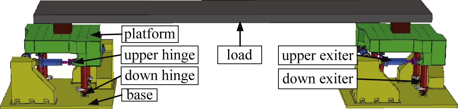
Fig.2
The top view diagram of the shaking tables.
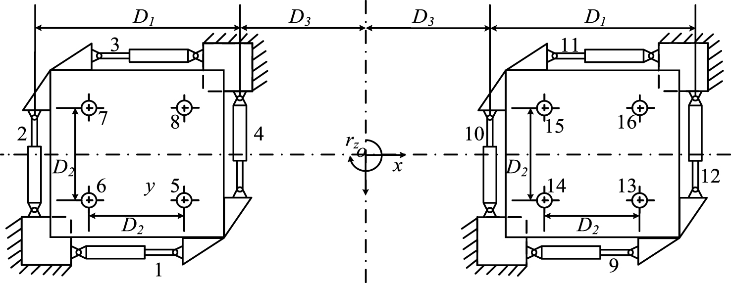
Fig.3
Schematic of double shaking tables control system.
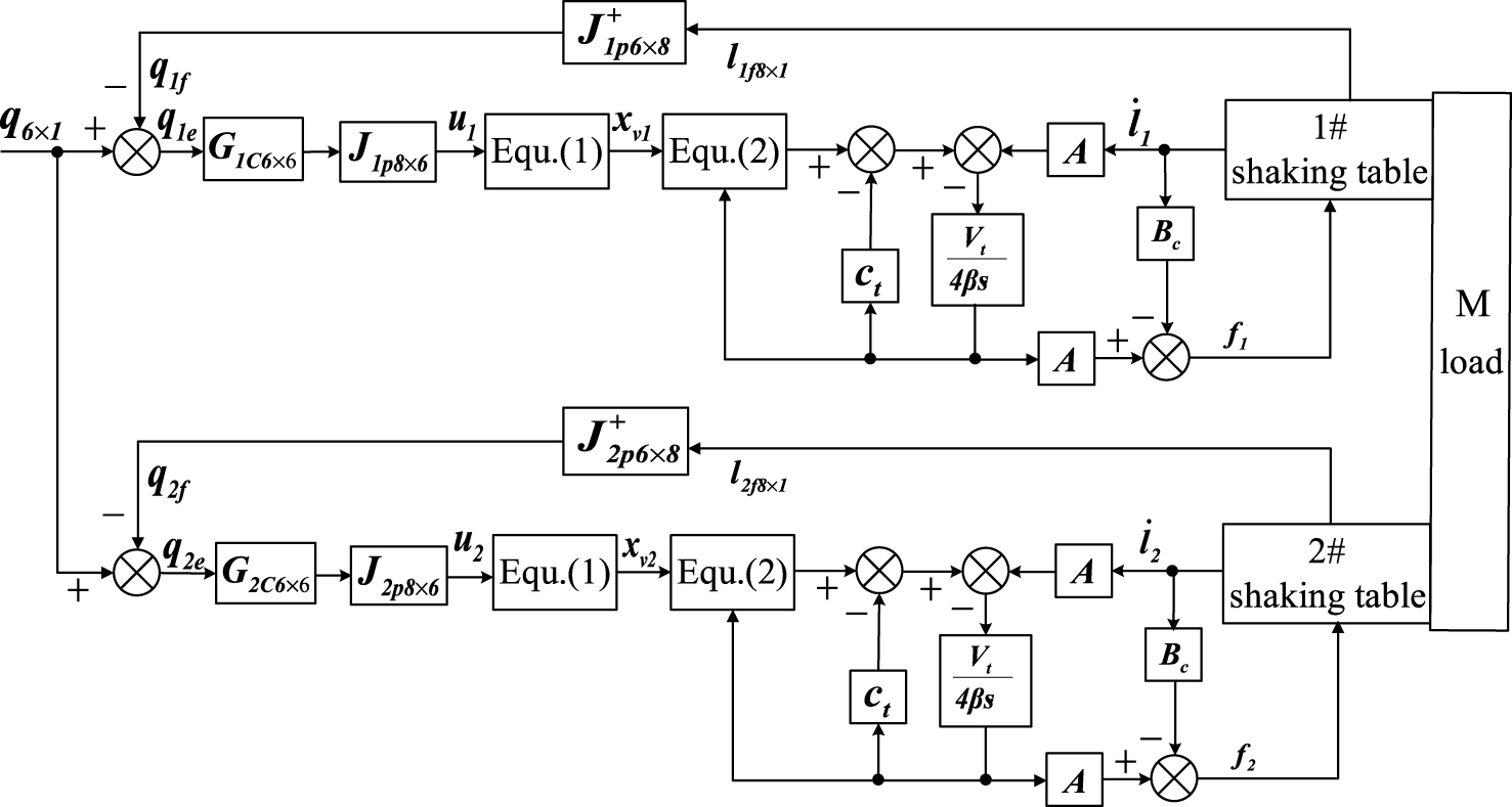
Fig.4
The proposed synchronous tracking control scheme.
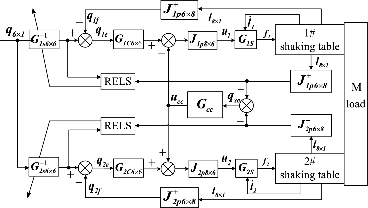
Fig.5
The CCC based on fuzzy PD control.
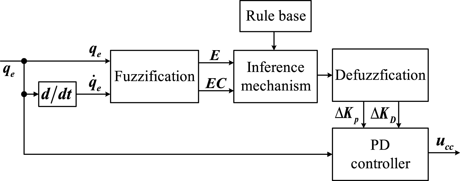
Fig.6
The membership functions for q e and q e .
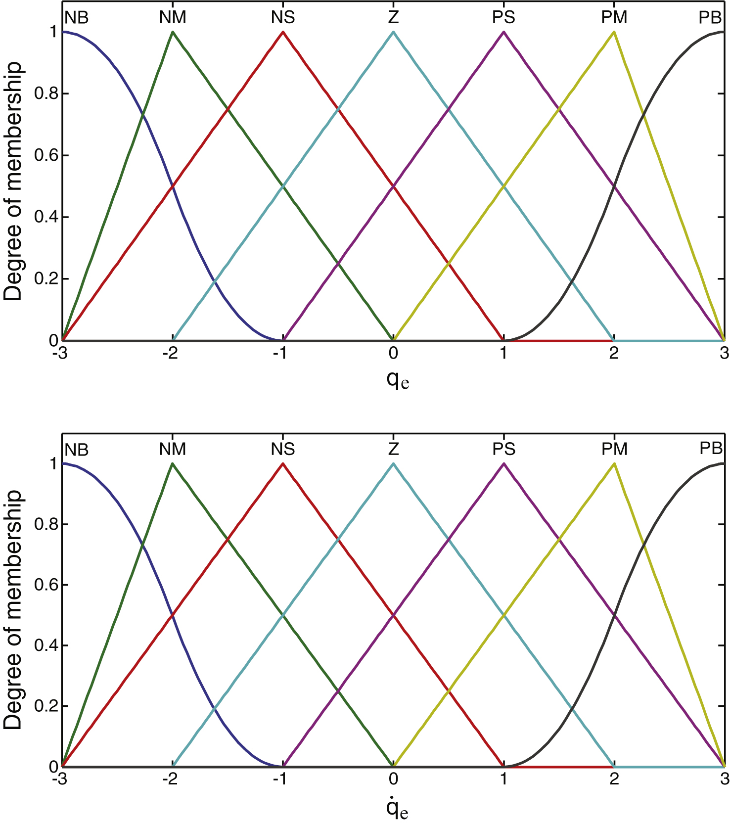
Fig.7
The membership functions for K p and K d .
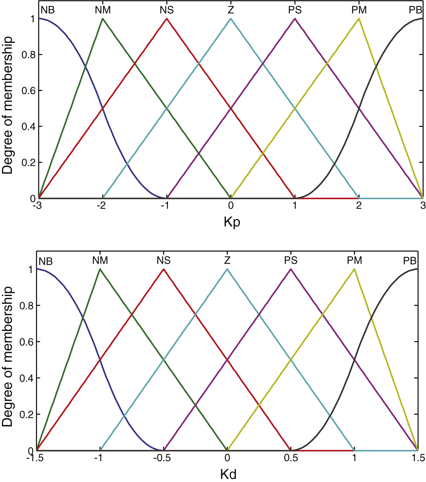
Fig.8
The control surface of self-tuning PD gains for FLC.
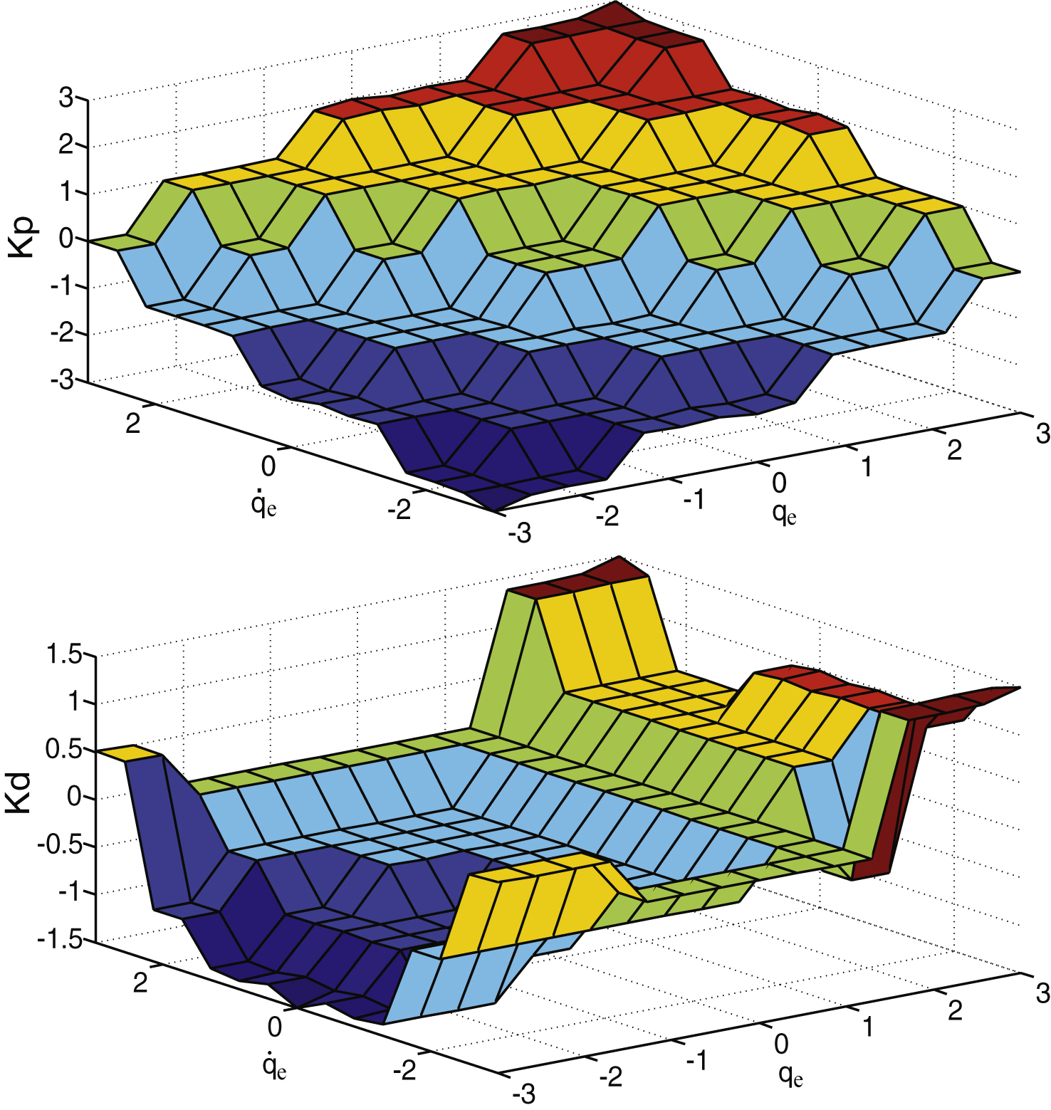
Fig.9
The proposed CCC based on hybrid fuzzy PD controller.
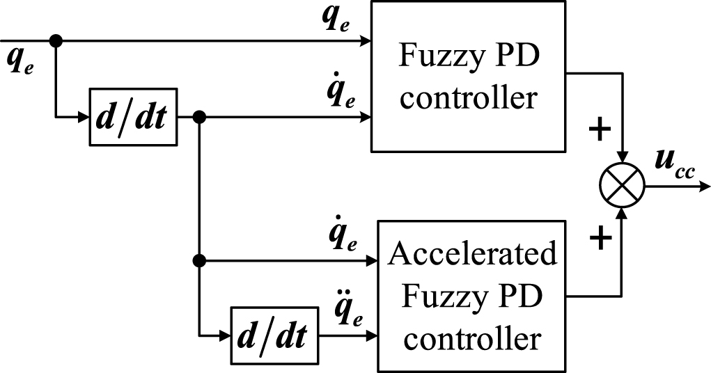
Fig.10
The FRFs and IFRFs of the shaking tables.
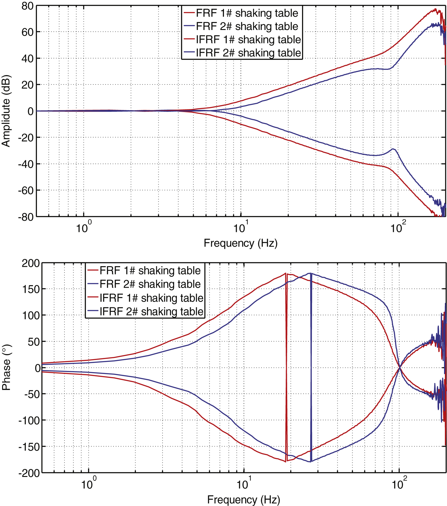
Fig.11
The FRFs of shaking tables after using AIC.
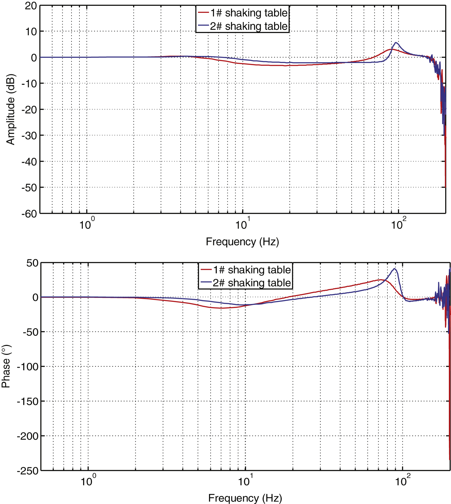
Fig.12
Comparisons of desired and response displacement.
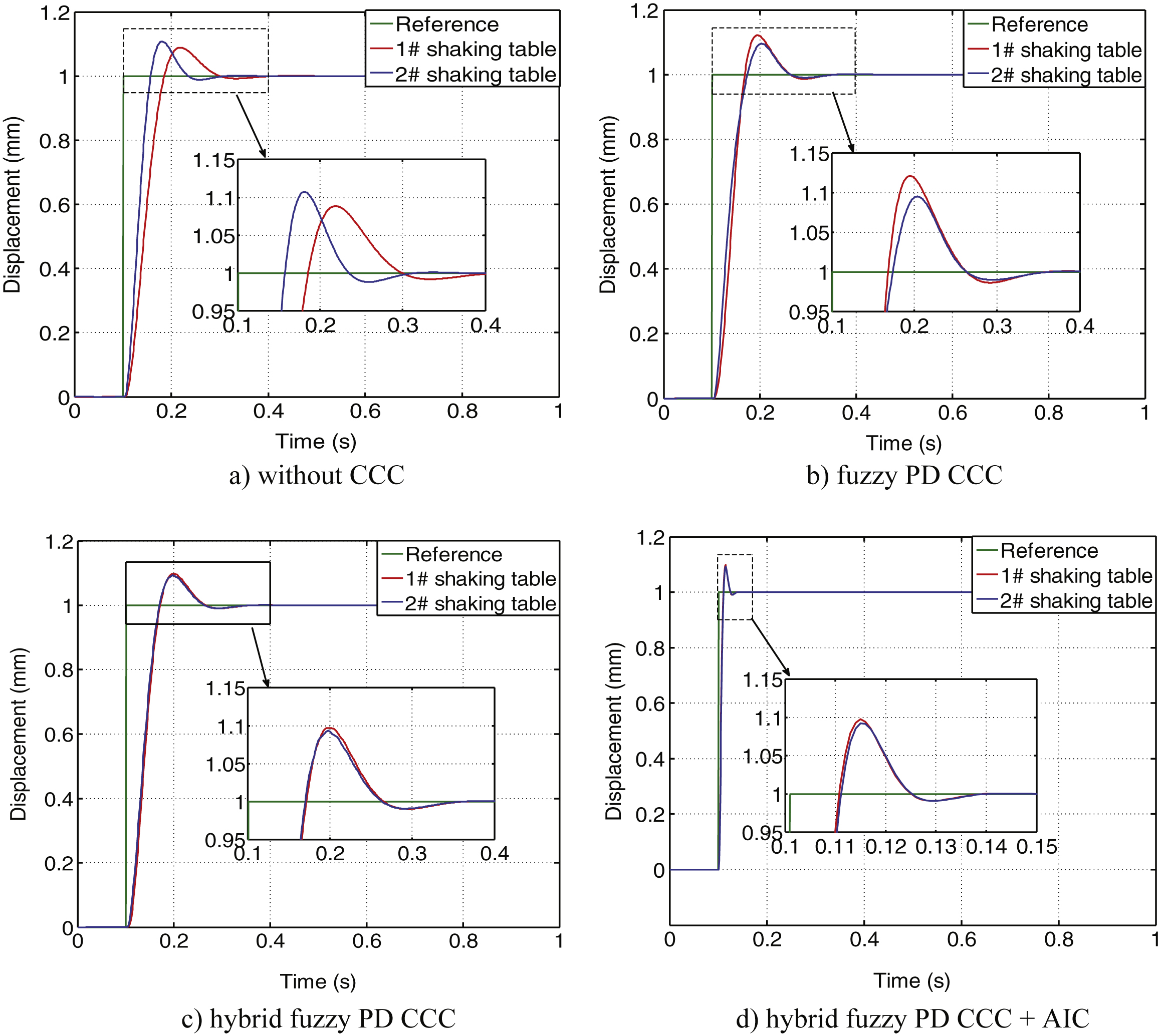
Fig.13
Comparisons of desired and response displacement.
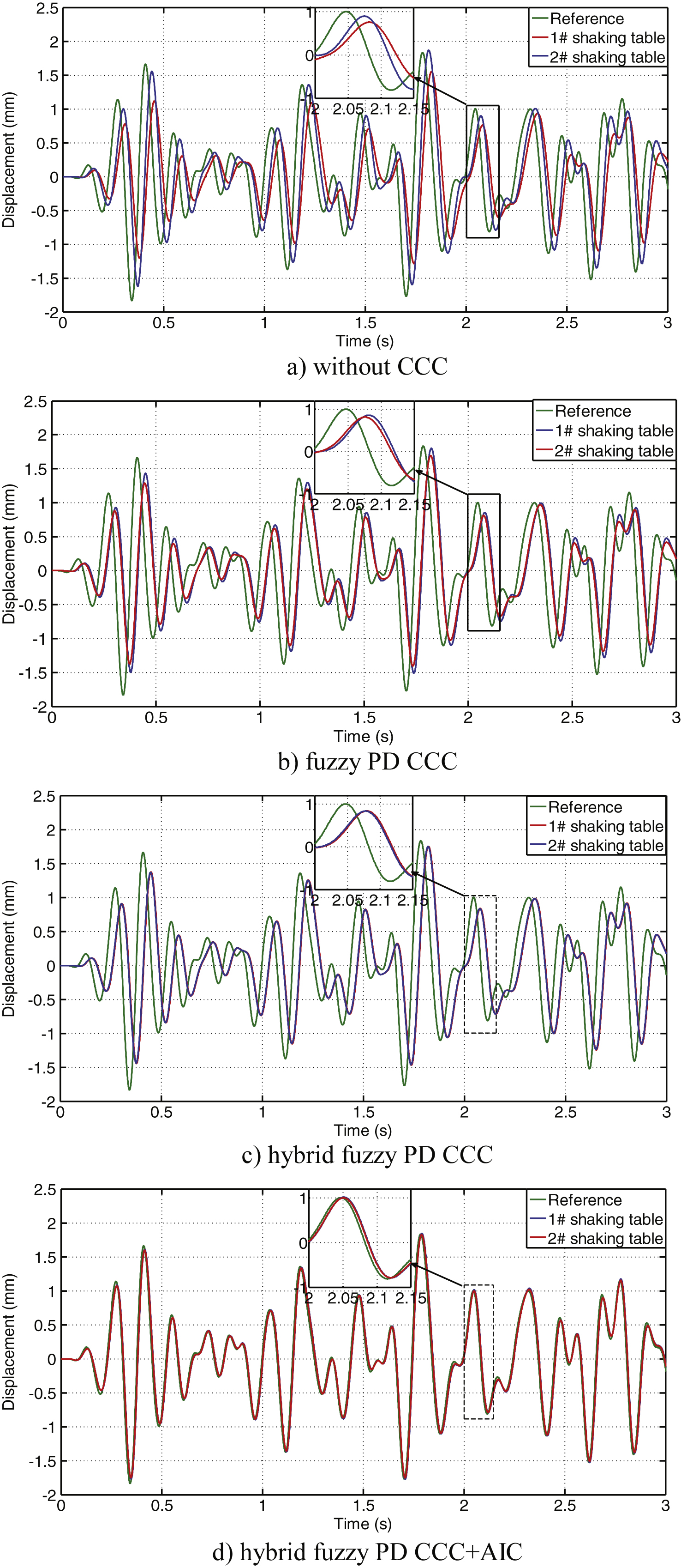
Fig.14
Comparisons of synchronization errors.
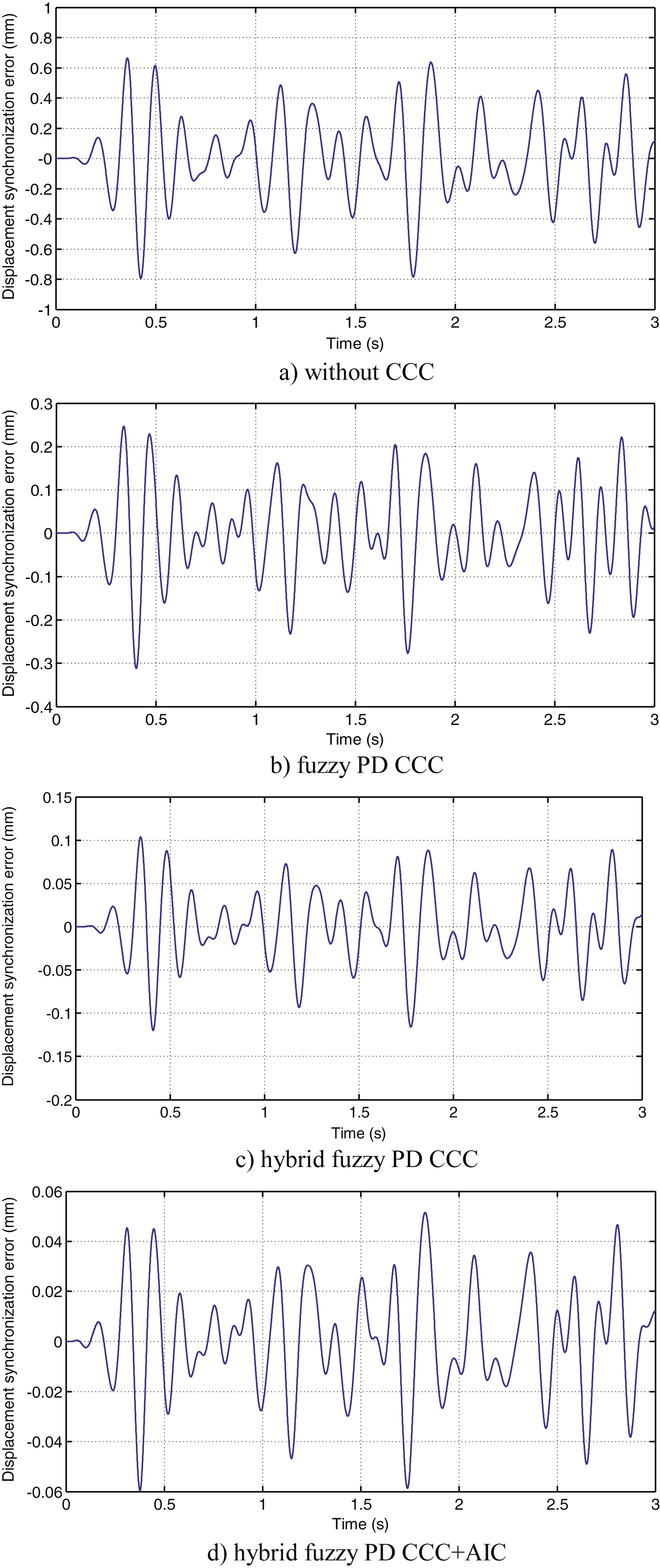
Fig.15
Comparisons of tracking errors.
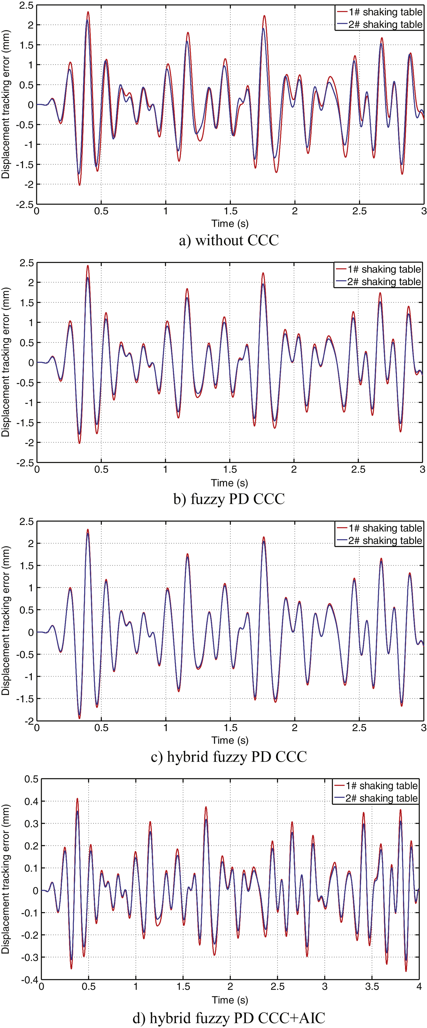
Table 1
Fuzzy rules for K P
| qe\ | NB | NM | NS | Z | PS | PM | PB |
| NB | PB | PB | PM | PM | PS | PS | Z |
| NM | PB | PM | PM | PS | PS | Z | NS |
| NS | PM | PM | PS | PS | Z | NS | NS |
| Z | PM | PS | PS | Z | NS | NS | NM |
| PS | PS | PS | Z | NS | NS | NM | NM |
| PM | PS | Z | NS | NS | NM | NM | NB |
| PB | Z | NS | NS | NM | NM | NB | NB |
Table 2
Fuzzy rules for K d
| qe\ | NB | NM | NS | Z | PS | PM | PB |
| NB | PS | NS | NB | NB | NB | NM | PS |
| NM | PS | NS | NB | NM | NM | NS | Z |
| NS | ZE | NS | NM | NM | NS | NS | Z |
| Z | ZE | NS | NS | NS | NS | NS | Z |
| PS | ZE | Z | Z | Z | Z | Z | Z |
| PM | PB | NS | PS | PS | PS | PS | PB |
| PB | PB | PM | PM | PS | PS | PS | PB |
Table 3
Main parameters of the shaking tables system
| Parameters | Values |
| Mass of the platform | 5000/kg |
| Mass of the load | 7500/kg |
| Distance of the two shaking tables | 12/m |
| Effective area of cylinder | 0.0075/m2 |
| Density of hydraulic oil | 845/kg/m3 |
| Nature frequency of servo valve | 120/Hz |
| Damping ratio of servo valve | 0.6/none |
| Rated flow of servo valve | 400 L/min |
| Pressure of hydraulic source | 25×106/Pa |
| Effective bulk modulus | 6.9×10⁸/Pa |
Table 4
Synchronization error comparison of the controllers
| Controller | Maximum error | RMS error |
| Without CCC | 0.794 mm | 0.281 mm |
| Fuzzy PD CCC | 0.312 mm | 0.103 mm |
| Hybrid fuzzy PD CCC | 0.120 mm | 0.042 mm |
| Hybrid fuzzy PD CCC +AIC | 0.062 mm | 0.022 mm |
Table 5
Tracking error comparison of the controllers
| Controller | Maximum error (1#/2#) | RMS error (1#/2#) |
| Without CCC | 2.33 mm/2.12mm | 0.815 mm/0.704mm |
| Fuzzy PD CCC | 2.42 mm/2.12mm | 0.820 mm/0.721mm |
| Hybrid fuzzy PD CCC | 2.31 mm/2.22mm | 0.786 mm/0.752mm |
| Hybrid fuzzy PD CCC + AIC | 0.413 mm/0.355mm | 0.139 mm/0.118mm |


