
Structural performance of GFRP connectors in composite sandwich facade elements
Abstract
A systematic testing and modelling program has been developed for the verification of the structural performance of facade sandwich elements to take structural aspects into consideration in the SESBE research project, focusing on the development of “smart” facade elements.
The present paper mainly focuses on the verification of the mechanical performance of the glass fibre reinforced polymer (GFRP) connectors of the novel type of facade element composed of reactive powder concrete (RPC) panels with foam concrete insulation between them. Because of the reduced thickness of the large facade elements, the performance of the connectors is critical for the entire structural concept. The first series of the testing and modelling programme concerning connector performance are presented here. The results suggest that sufficient strength and ductility of the connectors can be ensured using GFRP in the proposed thin light-weight facade elements.
1Introduction
1.1Background
The performance of building envelopes significantly influences the energy efficiency of buildings used for living and working. Furthermore, the production of materials and other processes used in construction, such as manufacturing of products, transportation and on-site operations might severely impact the environment. Therefore, it is essential to consider these aspects when selecting architectural concepts, manufacturing processes and materials for building facades.
To reduce the aforementioned negative effects, the project SESBE (Smart Elements for Sustainable Building Envelopes), funded by the European Commission, aims to improve energy efficiency of prefabricated concrete facades with a reduced use of materials. The overall objective is to develop smart facade elements, which are lighter, thinner and more adaptive than existing solutions through the utilization of nanomaterials and nanotechnology. The use of “smart" cost effective raw materials and cost saving technologies are expected to lead to:
• Increased energy efficiency,
• Increased fire resistance of materials,
• Increased surface functionality,
• Reduced price of the facade elements.
The use of novel materials and technologies requires that the structural performance, together with several other important requirements such as thermal and fire performance, moisture safety etc. should be carefully investigated and validated. Some insights into this validation process will be provided in the subsequent sections.
1.2Description of the proposed concept
The elements developed in this project are prefabricated facade elements, which are attached to the main load-bearing structure in situ. These types of elements, often called architectural concrete cladding, provide aesthetic, structural and isolating functions (FIP, 1998). The concept of the proposed system is illustrated in Figure 1 (left): the prefabricated facade elements are not part of the primary load-bearing system, which typically consists of slabs and load-bearing cross-walls. The sandwich elements are fixed to the main load-bearing structure at the building site using an anchorage system. Due to their large dimensions (7– 10×2.7– 3.0 m), the facade elements carry significant horizontal (wind) and vertical (self-weight) loads, which they transfer to the building frame.
The sandwich elements are composed of two thin (20– 25 mm) reinforced concrete layers with a lightweight foam concrete insulation between them, see Figure 1 (right). The reinforced concrete layers are made of reactive powder concrete (RPC) reinforced by carbon fibre reinforced polymer (CFRP) grids. To ensure that the inner and the outer layers act together, i.e. to transfer the loads between one another, they are linked by glass fibre reinforced polymer (GFRP) truss-like connectors as shown in Figure 2 (right).
The GFRP connectors, see Figure 2 (left), are produced with a pultrusion process, i.e. the reinforcing E-glass fibres impregnated with an epoxy resin were pulled through a machine where they were formed and cured. Since adhesion to concrete is critical for transferring stresses, the round profile was wound with an additional bundle of fibres to form helical ribs on the surface. The ribbed bars have a nominal diameter of 6 mm and the bending radius of the connectors is 12.5 mm.
The main challenge from a structural point of view during the development of these innovative facade elements is ensuring that they will resist the anticipated loads, e.g. wind and self-weight, and transfer them to the main structural frame in different design situations without posing issues of safety, serviceability, durability and robustness. The present paper gives an insight into this challenge and the concept development process to ensure an adequate structural behaviour of the facade elements.
2Process of concept development
2.1General considerations
To provide an attractive, comfortable, well-functioning, safe and sustainable built environment, a balance should be found between architectural, functional, structural, economic and environmental requirements as illustrated in Figure 3. However, these goals often contradict one another, meaning that careful planning is needed in order to find a compromise. This involves competences from several fields, such as architecture, building physics, structural engineering, economics etc. Furthermore, the aforementioned aspects often interact: e.g. energy performance of a building involves functional (e.g. building physics), economic (e.g. operation costs) and environmental issues (e.g. emission rates); the architectural concept has a significant influence on the structural frame and the overall costs of construction etc.
To ensure that the SESBE facade elements will perform as expected during the anticipated lifetime of the building, several of these aspects are addressed and developed in parallel. With this approach, an optimized, cost-effective and sustainable product is hoped to be achieved.
To meet the often unclear requirements of complex systems, such as a novel facade with various expectations, a top-down approach, called target cascading, is adopted (Kim, Michelena, Papalambros, & Jiang, 2003). The main goal is to progressively propagate the top level design requirements, the so called targets, to appropriate specifications for the various subsystem and component levels in a consistent and efficient way. This process is essential in the early development stages of complex products and systems. During the SESBE project the design targets of the different aspects are cascaded down from the general structural concept, through component behaviour, material properties and connection characteristics. Thus the necessary testing and modelling tasks could be identified and the structural performance could be validated by following a bottom-up direction. This enables a near optimal choice among different concurring alternatives within a reasonable time-frame. This bottom-up validation could be seen as the right-hand side of a Vee Model, as presented in Figure 4 (Forsberg, Mooz, & Cotterman, 2005). The Vee Model provides a great visual tool to organize the specification and validation process carried out in the testing and modelling programme. This approach is often used in industrial engineering especially in projects where strict quality assurance protocols need to be met by various suppliers e.g. in the automotive industry.
2.2Structural aspects
Perhaps the most fundamental requirement for any type of building is to ensure safety of occupants. However, there are other issues that need to be considered, such as functionality, user comfort, durability etc. Requirements for these aspects are regulated by building codes, which usually contain mandatory provisions and general recommendations. In Sweden, for example, the National Board of Housing, Building and Planning publishes a series of provisions on the Application of European Construction Standards (EKS), which together with the Eurocodes constitute the only system for the design of structures in Sweden (Boverket, 2015). Similar frameworks exist in other European countries. When developing a new facade component and/or system, it is advisable to review these regulations, since all the aforementioned requirements might have a significant influence on the development and design of the facade components.
The conditions for marketing construction products within EU’s internal market are harmonized by the Construction Products Regulation (European Commission, 2011). This, among many others, demands requirements for mechanical resistance and stability of construction products. The main purpose of the CPR is to harmonise the conditions for the marketing of construction products within EU’s internal market through simplification, clarification and increasing the credibility of the legislative framework for construction products (Nwaogu, Upson, Marshall, Le Crom, & Vermande, 2015).
Under the CPR, a Declaration of Performance (DoP) must be drawn up for the product that is covered by a harmonised European standard (hEN) or European Technical Assessment (ETA) and must be made available. CE marking is mandatory for construction products covered by a hEN. CE marking of a product not covered, or not fully covered, by a hEN, is also possible if the product conforms to an ETA issued by a Technical Assessment Body (TAB). The CE mark demonstrates that the performance of the construction product has been assessed in accordance with a hEN or the issued ETA.
As the facade sandwich elements developed in SESBE likely fall under the harmonized European Standard EN 14992 Precast concrete products – Wall elements (CEN, 2012), the requirements stated in this document should be taken into account during the development of the product.
However, even if a construction product is lawfully marketed in a EU/EES country, it does not mean that it fulfils national (or local) building regulations, which are applicable to the building itself. As mentioned before, the national building regulations often specify provisions and guidance on the application of European structural standards, i.e. the Eurocodes. Figure 5 illustrates how the standard requirements, European and national regulations are organised in a hierarchical structure.
The general part of Eurocodes, EN 1990 (CEN, 2002) describes the principles and requirements for safety, serviceability and durability of structures. It is based on the limit state concept used in conjunction with a partial factor method. The provisions in EN 1990 ensure that the building elements have an adequate reliability against failure. The structural integrity of the entire building is ensured by taking appropriate measures of designing for robustness.
Facade elements interact with the whole building shell and might influence its overall behaviour due to their significant weight, size and stiffness. Hence it is necessary to develop reliable calculation procedures to predict these effects and specify related performance requirements. For instance, the wind loads on the structure vary widely among regions where the facade elements are used. Therefore, methods should be available for modelling the structural frame and calculating loads and structural response in terms of internal forces, stresses, strains, dynamic effects etc.
The structural behaviour of a façade panel is significantly influenced by the anchorage system i.e. where and how it is connected to the main load-bearing structure and the amount of movement and rotation allowed at the joints. This is crucial for the consideration of local failure at the anchorage zone. To prevent the facade elements from falling, the anchorage should be designed to have sufficient resistance. To provide integrity of the entire structure, the ductility and stiffness of these joint should be sufficient to cope with extraordinary design situations such as e.g. explosions and impacts.
A major hurdle from a structural engineering viewpoint is to design the connectors between the RPC panels to ensure the adequate transfer of shear forces enabling composite action between the two panels. Through the composite action, the facade components resist bending moments as a whole: one panel taking up compression and the other one tension.
The proposed structural concept is verified by means of experimental testing and numerical modelling, which contributes to the development of simplified calculation procedures for practical purposes.
Besides pure structural considerations, the design concept should be manufactured in a time- and cost-effective manner. This requires a continuous discussion with material providers and manufacturers of the final product. As an example, in contrast to the steel bars, GFRP rods cannot be bent (the composite deforms elastically until brittle destruction). It is impossible to soften such material by heating (in the pultrusion process, thermosetting resins are usually used). Therefore, to create a curved connector the traditional production process needed to be modified: heaters were removed; caterpillars were replaced by a large reel mounted on the electric engine. The manufacturing process was divided into three main stages: 1) resin impregnated rebar (wet) with helical rib was wound onto the reel; 2) uncured rebar was manually formed into a zig-zag shape (by using a dedicated template) and 3) the connectors were cured in an oven. The foregoing method enables the production of connectors required for the SESBE project.
Similarly, handling, transportation and assembly issues should be taken into account even at early stages of the development process. These considerations limit the overall weight and sizes of the facade elements. Emphasis should be put on lifting the components, which requires special load cases for the panels.
The building envelope needs to maintain sufficient strength and stiffness under various loading conditions, thus the typical loads and configurations that are expected to act on the panel should be carefully analysed. Under normal circumstances the sandwich panels are subjected to wind and gravity loads. However, exceptional load cases (e.g. earthquake, explosion, fire) might also be important aspects for maintaining structural safety and serviceability. The loads to be taken into account during the development of the panels are derived from typical building configurations at various geographic locations with different climatic conditions. It is also essential that realistic boundary conditions are assumed when calculating the load effects.
When combining different materials, the compatibility of the materials due to relative deformations needs to be investigated e.g. different time and moisture-dependent behaviour (e.g. creep and shrinkage) and differences in thermal expansion and contraction. These phenomena might result in significant stresses due to restraining forces and lead to increased maintenance costs and reduced service life.
2.3Overall testing and modelling programme
To investigate the overall structural behaviour, a typical building was defined and the anticipated loading on the elements was determined, thus enabling the structural performance to be analysed both at system and component level (Flansbjer et al., 2015).
Based on the preliminary investigations, a detailed testing and modelling programme was defined to support the verification of mechanical resistance of the SESBE sandwich panels at various levels. A further purpose of this programme is to gain confidence concerning the reliability of the calculation methods. The structural modelling and testing is performed in parallel with the development and characterisation of the materials used for the components. Because the performance of the materials and the requirements at different levels interact, this is an iterative process as illustrated in Figure 6.
To study the structural behaviour of the facade element in the SESBE project, Finite Element (FE) calculations are carried out. The FE model helps to evaluate stresses, deformations and subsequent cracking as a result of the anticipated loads. Due to the combination of novel materials, simple analytical relationships are not yet developed, thus numerical simulations are beneficial, even in the early conceptual phase, to understand the underlying structural mechanisms. Because the complex modelling task is supported by experimental data, it is important to develop the numerical model in parallel with the testing activities. As mentioned earlier, an iterative procedure is thus applied to understand which tests should be carried out and what kind of information should be extracted from them (Figure 6). In the numerical modelling the material properties are used as input and the model is verified by its ability to reproduce the findings in the component tests regarding deformations, crack formations, etc., thus the procedure gives feedback to the material development discussed elsewhere (Mueller et al., 2015).
This investigation covers not only the facade elements, but also their anchorage system. The calibrated structural model provides a better understanding of the physical mechanisms governing the structural behaviour of the facade elements and their interaction with the existing load-bearing structure under different load conditions including dead loads, wind loads, impact loads, as well as temperature and moisture variations.
The primary outcome of the testing and modelling programme is the dimensional constraints for the facade element and restrictions concerning the thickness, in particular of the RPC panels and the GFRP connectors. Furthermore, it also provides a basis for the design of the anchorage system and other connection details. In the next section some results of the test concerning the connectors is presented and discussed.
3Verification of connector performance
According to the relevant hEN, i.e. EN13369, the mechanical resistance of a precast construction product can be verified by 1) calculation, 2) calculation aided by testing and 3) testing (CEN, 2013). The standard also states that the verification by calculation shall be consistent with EN-1992-1-1, i.e. the general rules for concrete structures (CEN, 2004). For novel structural arrangements advanced calculation models might be needed, which are not covered by the relevant standards. Thus physical testing is required to verify the reliability of a design model assumed for calculation. In some cases, direct load testing is the only way to verify the declared performance of the construction product.
3.1Preliminary modelling
At an early stage, initial FE calculations were performed using Abaqus/CAE 6.14-1 (Dassault Systèmes, 2014) on different configurations of large scale sandwich elements to better understand the structural behaviour and to identify critical parameters (this is highlighted with the first shaded box of the chevron diagram in Figure 6). The calculations were primarily used to verify that the general concept of the sandwich element was viable and to check the effect of connector geometry, connector spacing, panel thicknesses and boundary conditions on a larger scale. The calculations were performed with second order theory with respect to large deformations.
One of the analysed sandwich element configurations is illustrated in Figure 7. The element has a size of 3 × 6 m and consists of a 25 mm RPC outer facade panel, 150 mm foam concrete insulation and a 25 mm RPC inner panel. The two RPC panels were connected by four GFRP bar connectors with a nominal diameter of 6 mm, one at the location of each anchorage point in the horizontal direction. The boundary conditions at the lower anchor points were prescribed to transfer both vertical (V) and horizontal (Hl) loads to the load-bearing structure, while the upper anchor points were prescribed to only transfer horizontal (Hu) loads.
The model consists of separate parts for the outer facade panel, foam concrete, inner panel and connectors. The panels and foam concrete were modelled with 8-node linear continuum shell elements, while the connectors were modelled with linear beam elements. The facade (outer) panel and inner panel were attached to the foam concrete using tie constraints, i.e. full interaction was assumed at the interface in the preliminary model. The interaction will be discussed further in Section 3.3. The connectors were attached to the centre of the panels using tie constraints to allow for actual connector geometries to be modelled. A screenshot of the FE model with the connectors highlighted is shown in Figure 8.
In this initial stage, linear elastic material models were used to describe the material behaviours. More advanced material models will be used later in the process when the need to simulate more complex phenomena occurs, e.g. concrete cracking, interface interaction. The parameters of the material models are given in Table 1. The element was subjected to the self-weight of the different components and a wind pressure load of 1000 Pa acting on the facade panel.
The sandwich element can be treated as one-way spanning between the connecting floor element above and below. Primary load-bearing of the wind load is thereby achieved by bending in the short direction of the element. There is also secondary load-bearing in the longitudinal direction of the element, where the wind load is transferred to the stiffer regions at the connectors by local bending of the panels. The bending stiffness and strength of the individual RPC panels are too low to withstand the wind loads in the primary load-bearing direction. Therefore, the shear force transfer between the outer and inner panel becomes the key element in achieving composite action when the sandwich element is subjected to bending. Composite action allows one panel to act in compression while the other acts in tension. The uncertainty regarding the mechanical performance of the foam concrete, specifically shear stiffness and shear strength, means that the insulation may have a very limited ability to transfer shear forces. To be on the safe side in design, the foam concrete should be treated as non-load-bearing, whereby the shear force transfer should be restricted to the connectors. However, here the foam concrete was included since the main purpose was to establish a FE model that can simulate the structural behaviour of the sandwich element in a realistic way. The degree of composite action mainly depends on the connector configuration: besides bending from transverse actions the connectors also transfer the self-weight of the facade panel and, to some extent, the self-weight of the foam concrete, to the innerpanel.
Calculations of different connector configurations indicate that the force in the connectors is primarily axial and that the bending and shear forces are negligible. The maximum axial force in the connectors for configurations similar to Figure 7 is found to be in the order of 1-2 kN, both in tension and compression. The main concern is not the capacity of the GFRP connectors themselves, which have a tensile strength of 30 kN (corresponding to a nominal strength of 1012 MPa); rather, the challenge is to ensure that the connector force can be transferred into the thin RPC panel without local pull-out failure. This will be discussed further in Section 3.2.1.
An important aspect here that needs further investigation is the deformations in the serviceability limit state. Deformations obtained by the initial models are relatively small: 1.3 mm maximum deformation for 1000 Pa wind pressure, as shown in Figure 8. This load level is in the order of the serviceability wind load acting on an ordinary building and the calculated displacements are less than the usual deflection limits in prescriptive design code, e.g. L/250 in EN 1992 (CEN, 2004). However, further investigation needs to be performed in order to determine realistic deflection limits for such elements in terms of appearance and damaging deflections.
If the connector spacing is reduced, i.e. the number of connectors is increased; the forces in the connectors become lower. Further, more connectors result in greater composite action between the outer and inner panel, which increases the element stiffness with less deformation as a result. Reduced connector spacing also reduces the section forces in the panels in the secondary load-bearing direction. However, due to production aspects, thermal aspects and costs, the number of connectors should not be higher than necessary.
The preliminary results showed that the stresses in the panels are rather small in general, and no cracking is expected for the current loads because tensile stresses are below the tested tensile strength of the RPC panel (around 5 MPa). However, this global structural model does not reflect local stress conditions in a fully accurate way, e.g. in the vicinity of connectors and anchorages. This has to be checked by local models and/or verified by tests. Furthermore, the stresses and deformations will be higher when openings for doors and windows are included in the element.
The calculation model also provided preliminary values of the reaction forces to be used in the design of anchor details. The vertical reaction force (V) is due to the self-weight of the element, while the horizontal reactions forces (Hu and Hl) can be predominantly attributed to the wind load, but also include supplementary forces necessary to prevent the element from rotating, due to the eccentricity of the centre of gravity of the element. As an example, a summary of the reaction forces for the sandwich element configuration illustrated in Figure 7 is given in Table 2. The numbering of the anchor locations refers to the order of connector lines given from left to right in Figure 7. As the boundary conditions are statically indeterminate the reaction forces depend on the position of the anchors as well as the structural response of the element. However, simplified load distribution models can be applied.
3.2Testing activities
The purpose of the mechanical testing is to demonstrate that the facade element meets the requirements defined in EN 1992-1-1 for both the ultimate and serviceability limit state. It should also be kept in mind that, according to EN 13369, “initial type testing shall be carried out to demonstrate the conformity to the requirement before a new type of product is put on the market”. The current testing activities might provide useful experiences for the planning of such tests.
In the following section, some test results mainly focusing on connector performance will be discussed. The main requirement concerning mechanical connectors is that they shall a) resist design actions and b) have the necessary ductility (CEN, 2013). Further planned experiments will only be briefly mentioned, whereas development of the numerical model will be discussed in a subsequent paper.
3.2.1Local failure tests
The first sub-component tests were small-scale tests of the connectors embedded in the concrete. Pull-out tests were carried out with different geometrical configurations containing a small part of the connector and one concrete panel as depicted in Figure 9. The pull-out specimens consist of a 50 × 400 × 400 mm RPC panel with an embedded connector section. The specimen was placed in an inclined supporting steel frame, so that the load was applied along the connector at an angle of 45° from the face of the RPC panel. The loading condition in these tests is similar to that of the attachments of the connectors to the RPC panels in the sandwich elements, where the axial force in the connector is introduced to the panel.
The purpose of the pull-out tests was to help a) determine convenient connector options and geometry; b) determine relation between the embedment depths and pull-out strength and c) investigate how a local thickening of the RPC panel affects the results.
The results are used to verify the performance and to select connector systems for further development and testing. The results are also used to determine the connector capacity in the numerical models.
The embedment depth c becomes a critical parameter particularly when dealing with thin facade panels such as is the case of the textile reinforced RPC panels. The relationship between the pull-out strength and embedment depth was evaluated for the GFRP connector and compared with a steel bar connector as reference. Contrary to the GFRP connector, the steel connector was provided with a longitudinal bar that is spot welded to the connector bend, similar to traditional truss connectors. Illustrations of the different configurations are shown in Figure 10.
In most cases the pull-out capacity was determined by spalling of the concrete cover, which resulted in a brittle failure (no reinforcement was used in the panels). There seems to be a rather linear relation between the embedment depth and pull-out load capacity related to concrete spalling. Figure 11 shows that the steel connector has a higher pull-out capacity compared to the GFRP connector for smaller embedment depths. This might be explained by the extra longitudinal bar, which provides a larger contact area against the concrete and also reduces the local stress concentration in the RPC at the bend of the loaded steel bar compared to the bend of the GFRP bar.
In addition, two extra configurations with a 100 mm wide build-up along the GFRP connector were also evaluated (see Fig. 10c). The height h of the build-up was 10 and 20 mm, respectively. For the panels with a 10 mm thick build-up, the total embedment depth of the GFRP connector was around 20 mm, and the pull-out capacity showed to be very similar to the basic configuration with an embedment depth of 20 mm. Hence, a local build-up along the connector seems to be an effective way to increase the pull-out capacity without making the entire panel thicker. However, this effect was not as pronounced for the 20 mm thick build-up. This can be explained by the thickness of the build-up not being fully utilized, since the fracture surface in these cases developed towards the sides of the build-up. Hence, to achieve maximum potential contribution to the pull-out strength, the width of the build-up also has to be considered. From the results one can conclude that the pull-out strength for all cases, except for the GFRP connector with the smallest embedment depth, is higher than the maximum axial connector force (about 2 kN) determined from the preliminary structural model described earlier. In a 25 mm thick RPC panel, the embedment depth of the GFRP connector will be around 10 mm, which corresponds to a pull-out strength of around 4 kN. However, since the pull-out strength will be an ultimate limit state parameter, there has to be a sufficient safety margin. Additional tests are planned in order to provide a better statistical basis for the determination of design values for the pull-outstrength.
3.2.2Shear tests
The shear behaviour between the outer and inner panel is of vital importance to transfer the self-weight of the outer facade panel and to provide composite action when the sandwich element is subjected to bending under wind load. Therefore, the second series of sub-component testing focused on the shear behaviour of the connectors.
In these tests, a short strip of the sandwich panel was produced containing two connector rows. One of the panels was supported, while the other one was loaded in its plane as shown in Figure 12. Thus the panel (and the connector) is subjected to shear. A similar test setup has been used in previous works (Malaga et al., 2012; Flansbjer et al., 2013).
The main objective of these tests was to characterize the shear behaviour for different connector configurations and, based on the results, select connector systems for further development and testing. The shear test specimens and the test set-up were designed based on preliminary studies by FE modelling (see Section 3.3).
The specimens consist of a 25 mm outer facade RPC panel, 150 mm insulation of foam concrete and a 60 mm inner RPC panel (Figure 12). Both panels were reinforced with two layers of carbon grid. The height of the specimens is 1100 mm, whereas the width is 500 mm for the facade (outer) panel and 700 mm for the inner panel. The two RPC panels were connected by two connector rows in each specimen.
Four different GFRP connector configurations were tested (Figure 13) with two different connector layouts (Figure 14). The first “basic” configuration (B) consists of a single GFRP connector at each connector row. The second configuration (C) is identical to the basic configuration except that the foam concrete was removed before testing in order to study how the foam concrete contributes to the shear behaviour. In the third configuration (D) the RPC panels were provided with a 10 mm high and 100 mm wide build-up along the connectors. All these configurations had a single connector layout as shown in Figure 14 (left). Finally, in the fourth configuration (E) each of the two connector rows were provided with double layout GFRP connectors, which were mirrored along the longitudinal axis with respect to each other, as shown in Figure 14 (right). The two connectors were attached to each other by plastic stripes at the intersection points. As in the pull-out tests a steel bar connector (A) was tested as reference.
The test specimen was placed in a supporting steel frame structure so that the bottom edge of the inner panel was supported in the vertical direction and the extensions of the inner panel were supported in the horizontal direction. The top edge of the (outer) facade panel was loaded in the vertical direction and the relative shear displacement between the facade panel and the inner panel was measured. A comparison of the shear behaviour of the steel connector and the four different GFRP connector configurations is presented in Figure 15.
For the basic GFRP configuration without foam concrete (C) it could be observed that the non-linear behaviour was initiated by successive buckling of the compressed GFRP bars and that pull-out of the upper bars in tension occurred shortly after the maximum load was reached. The basic GFRP configuration with foam concrete (B) showed a similar behaviour as the test without it (C). However, the initial stiffness and resistance was somewhat higher, which can likely be explained by a) a delayed buckling of the compressed GFRP bars due to the surrounding foam concrete and b) the fact that the foam concrete might also transfer some load between the outer and inner panel. The scatter between the three tests can probably be explained by differences in the occurrence of buckling of the compressed bars and differences in actual embedment depth.
The configuration with build-up RPC panel along the connectors (D) showed a more linear and stiffer behaviour to higher load levels, probably due to the shorter buckling length of the GFRP bars. The higher resistance is a result of the higher pull-out strength due to a larger embedment depth (20 mm), as was proved in the pull-out tests.
The configuration with double connectors (E) showed a strong linear behaviour with high stiffness and resistance, even higher than that of the steel connectors. The high resistance cannot solely be explained by the double amounts of connection points compared to the basic configuration. The interconnection of the connectors at the cross points likely delays the buckling of the compressed bars, which contributes to the higher resistance. This solution seems very promising because it is much easier to manufacture compared to the configuration with build-up RPC panel (D) and also has better performance. Another important advantage is that in a facade element, the double connector configuration will work in the same efficient way both in wind suction and wind pressure.
A general observation was that no cracks or other damages were observed on the outer surface of the facade panel during testing of any of the specimens. Furthermore, a relative movement occurred at the interface between the foam concrete and the inner RPC panel during testing in all cases, never between the foam concrete and the outer facade panel. This is probably an effect of the casting order: in the first case, the foam concrete is cast on top of the inner RPC panel and in the latter case the outer RPC panel is cast on top of the foam concrete. After the tests, major cracking and spalling was observed along the connectors and it was concluded that the compressed GFRP bars had been subjected to buckling. Another important observation is that all samples exhibit a relatively ductile failure, although both RPC and GFRP are considered very brittle materials. This can be very beneficial from a safety point of view as sudden failure of the elements can be avoided.
3.3Modelling of shear transfers
As indicated earlier, FE modelling using Abaqus/CAE 6.14-1 (Dassault Systèmes, 2014) was performed on different configurations of shear tests of sandwich element connectors before testing. The calculations were primarily used to verify that the proposed testing method would lead to the desired load distribution and to give information about expected failure loads and mechanisms. As for the preliminary structural model described in Section 3.1, the shear test model consists of separate parts for the facade panel, foam concrete, inner panel and connector. The panels and foam concrete were modelled with 8-node linear continuum shell elements, while the connectors were modelled with linear beam elements. The connectors were attached to the panels using tie constraints. The material properties given in Table 1 were used as input. Additionally, rigid bodies were used to represent the supports in the test rig. A screenshot of the modelled geometry and deformation plot are shown in Figure 16.
After testing, the models of the different GFRP configurations (B-E) were updated and verified by comparison with the shear test results. Based on the observations from the tests, it was realized that the first assumption of full interaction between the foam concrete insulation and the inner panels resulted in an incorrect shear load transfer through the insulation. Therefore, the interaction between the inner panel and the foam concrete were modelled by a contact surface formulation, where the tangential behaviour of the contact property assumes a friction coefficient and the normal behaviour is assumed to be hard contact with the ability to separate after contact. It was found that the shear behaviour was best modelled using a frictionless contact condition, i.e. coefficient of friction μ = 0. As it can be seen in Figure 15, there is a good correlation in the global response between test and analyses in the pre-peak regime. This means that the foam concrete has a negligible contribution to the shear transfer but contributes to the overall behaviour by normal compressive stress transfer and by that, stabilizing and retaining the spacing between the two panels. Furthermore, the buckling of the compressed bars of the connector seems to be captured in a realistic way, corresponding to the findings in the tests. The failure process of the shear specimens is not simulated accurately, because it is mostly attributed to successive local pull-out failure of the connectors, which is not included in the model at this stage. However, the axial tensile loads in the modelled connectors are in the range where the connectors reach their pull-out strength for the current embedment depth (Figure 11) at the point where the calculation model results begin to deviate from the test results, which corresponds to the initiation of the failure process in the shear specimen. A description of the pull-out failure process will be included in the FE model at a later stage.
3.4Further testing and modelling steps
As discussed earlier, the structural behaviour of the sandwich elements depends highly on the stiffness and strength of the GFRP connectors to ensure composite action between the inner and outer RPC panel. Therefore, in the third series of tests, a full-length strip of sandwich panel containing two rows of connectors will be subjected to 4-point bending. This test will serve as a verification of connector performance and composite action and calibration of the numerical model.
In the final series of testing, the entire component will be investigated in a pressure chamber (capacity ≈±3 kPa). Both pressure and suction will be applied to simulate the cyclic effect of wind loading. Although the specimens will be slightly smaller (3 × 3m) than the final product, due to the limitations of the testing device, they will enable studies to be performed on full storey height elements including several connectors. These tests will support the verification of structural performance and the validation of the numerical model taking into account connectors and anchorages.
The verified numerical model will serve as a basis for virtual experiments on more complex element configurations and larger sizes.
4Conclusions
This paper a) described how structural aspects are taken into consideration in the SESBE research project aiming to develop novel architectural facade elements and b) presented some preliminary test results concerning connector performance. Because the timeframe of the project is limited, compared to the traditional development of construction products and systems, a systematic testing and modelling programme is planned to aid in the verification of the structural performance of the facade sandwich elements.
The high-level structural requirements are broken down into more specific performance targets at component and sub-component levels to define necessary testing and modelling tasks for validation of the structural performance in a bottom-up fashion. This concept has been illustrated in the paper and linked to relevant technological standards.
Findings of the first series of the testing programme have been presented with a main focus on connector performance. The results suggest that sufficient strength and ductility of the connectors can be ensured using GFRP in the proposed thin light-weight facade elements.
Acknowledgments
The SESBE project is funded within the Framework Programme 7 under the Grant Agreement no. 608950. The authors would like to thank the European Commission for funding the project and making this work possible.
References
1 | Boverket ((2015) ). BFS 2015:6 EKS 10 – Boverket’s mandatory provisions amending the board’s mandatory provisions and general recommendations (2011:10) on the application of European design standards (Eurocodes), Boverket (in Swedish). |
2 | CEN ((2002) ). EN 1990 Eurocode: Basis of Structural Design . European Committee for Standardization, Brussels, Belgium. |
3 | CEN ((2004) ) EN 1992-1-1: Eurocode 2: Design of concrete structures – Part 1-1: General rules and rules for buildings . European Committee for Standardization, Brussels, Belgium |
4 | CEN ((2013) ) EN 13369: Common rules for precast concrete products . European Committee for Standardization, Brussels, Belgium. |
5 | CEN ((2012) ) EN 14992: Precast concrete products – Wall elements . |
6 | Dassault Systèmes ((2014) ). Abaqus/CAEUser’s Guide, 2014, ABAQUS Version 6.14. |
7 | European Commission ((2011) ). Regulation (EU) No 305/2011 of the European Parliament and of the Council of 9 March 2011 laying down harmonised conditions for the marketing of construction products and repealing Council Directive 89/106/EEC. |
8 | FIP ((1998) ). Planning and design handbook on precast building structures. London, UK: SETO Ltd. |
9 | Flansbjer M. , Malaga K. , Tammo K. , & Blanksvärd T. ((2013) ). Alternative anchorage systems for textile reinforced concrete elements. In: First International Conference on Concrete Sustainability, JCI, Tokyo. Japan. |
10 | Flansbjer M. , Honfi D. , Mueller U. , Wlasak L. , Williams Portal N. , Edgar J.-O. , & Larraza I. ((2015) ). Structural behaviour of RPC sandwich facade elements with GFRP connectors, VII International Congress on Architectural Envelopes, San Sebastian-Donostia, Spain. |
11 | Forsberg K. , Mooz H. , & Cotterman H. ((2005) ). Visualizing Project Management: Models and Frameworks for Mastering Complex Systems. Hoboken, NJ: JohnWiley & Sons. |
12 | Kim H. M. , Michelena N. F. , Papalambros P. Y. , & Jiang T. ((2003) ). Target cascading in optimal system design. Journal of Mechanical Design, 125: (3), 474–480. |
13 | Malaga K. , Flansbjer M. , Tammo K. , Blanksvärd T. , & Petersson Ö. ((2012) ). Textile reinforced concrete sandwich panels. In International FIB Symposium-Concrete Structures for Sustainable Community, Stockholm, Sweden (pp. 11–14). |
14 | Mueller U. , Williams Portal N. , Flansbjer M. , Da Silva N. , Malaga K. , Chozas V. , Larraza I. , & Vera J. ((2015) ). Reactive powder concrete for facade elements – A sustainable approach. In: VII International Congress on Architectural Envelopes, San Sebastian-Donostia, Spain. |
15 | Nwaogu T. , Upson S. , Marshall S. , Le Crom Y. , & Vermande H. ((2015) ). Analysis of the implementation of the Construction Products Regulation – Executive Summary & Main Report, European Union. |
Figures and Tables
Fig.1
SESBE facade concept (left) and innovative sandwich facade element (right).
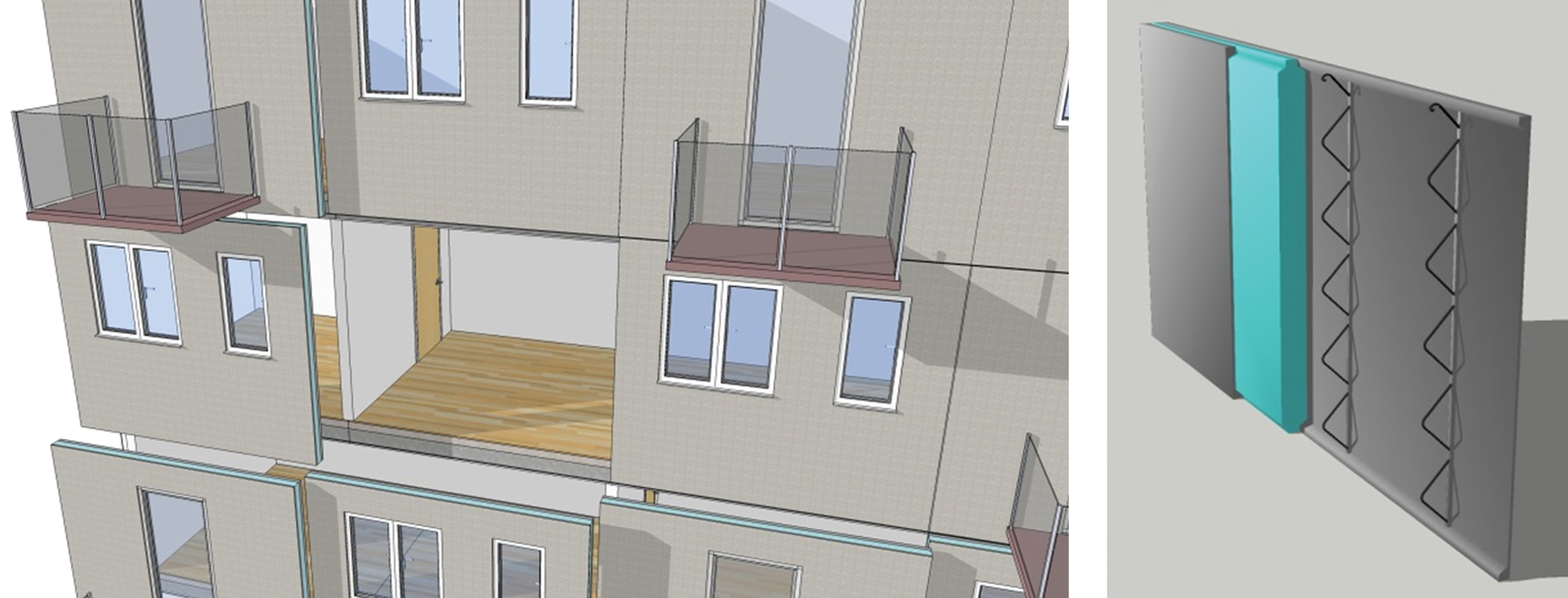
Fig.2
GFRP bar with the helical ribbed surface (left) and how the connector is attached to the CFRP grid before casting the concrete (right).
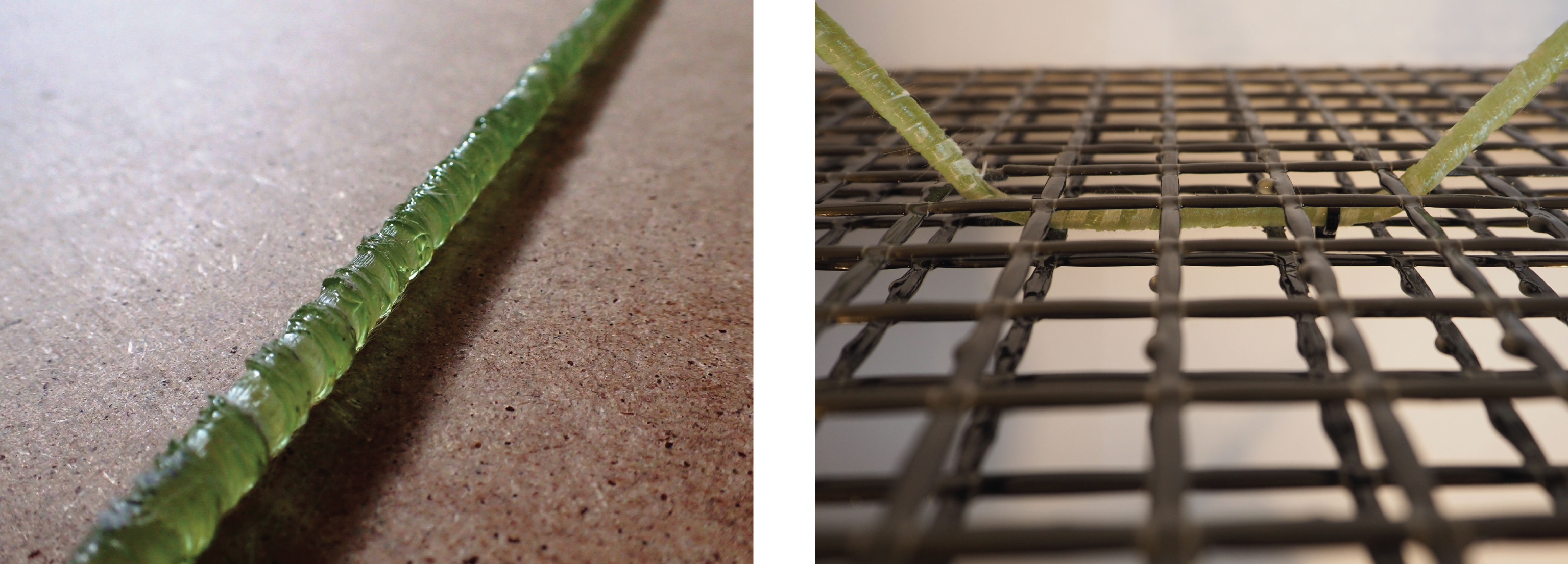
Fig.3
Concurring and interacting design aspects.
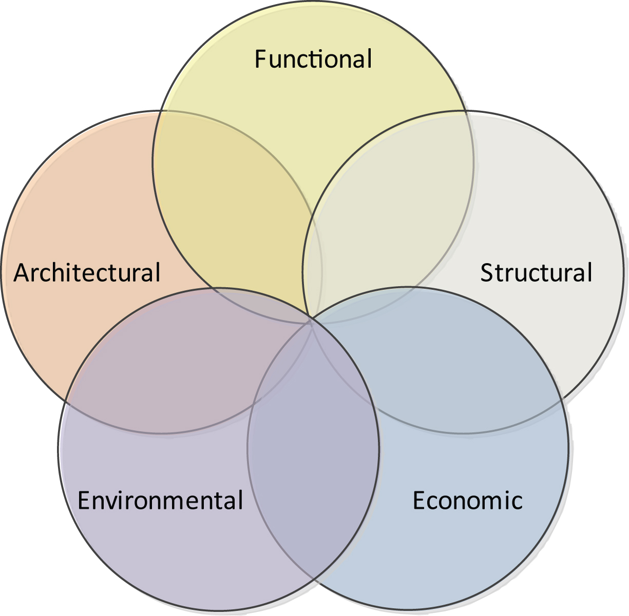
Fig.4
The Vee Model representation (adopted from Forsberg et al., 2015).
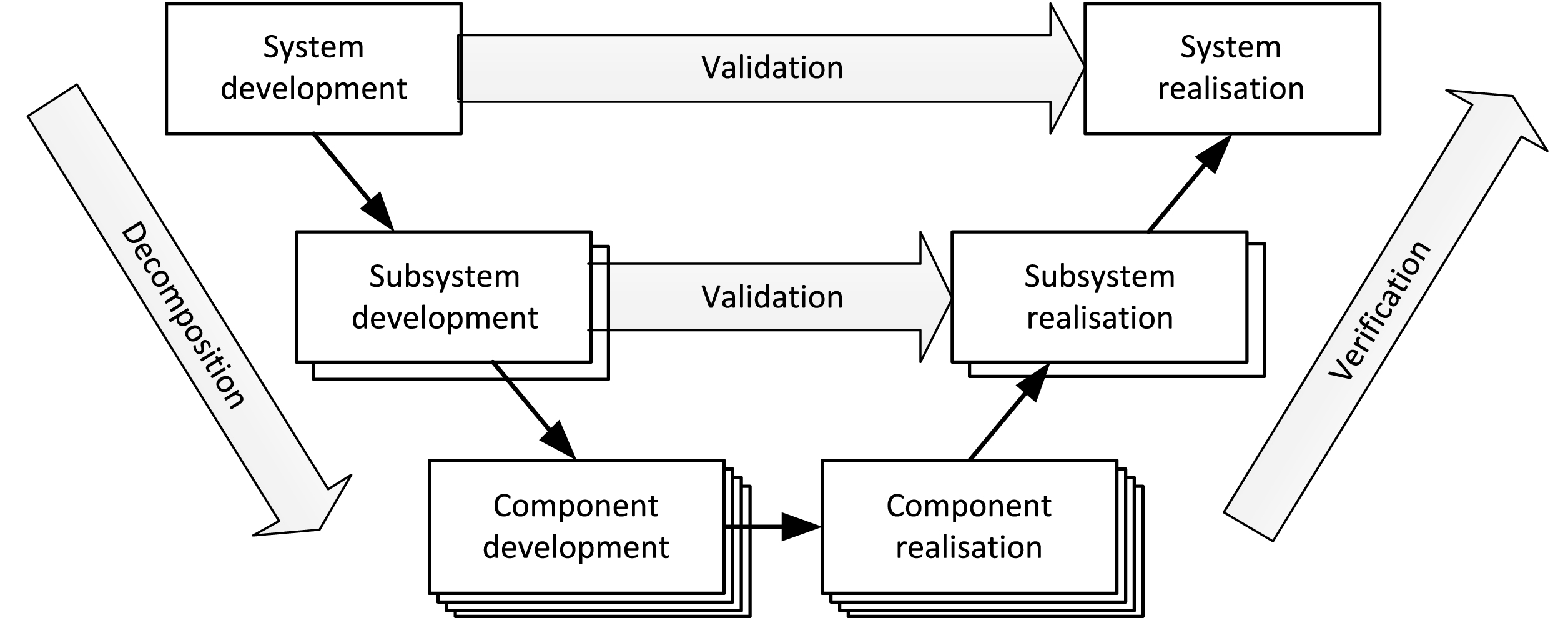
Fig.5
Illustration of hierarchy of some regulations and requirements relevant for the concept.
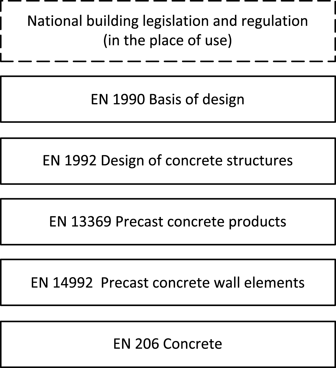
Fig.6
Summary of testing and modelling programme.
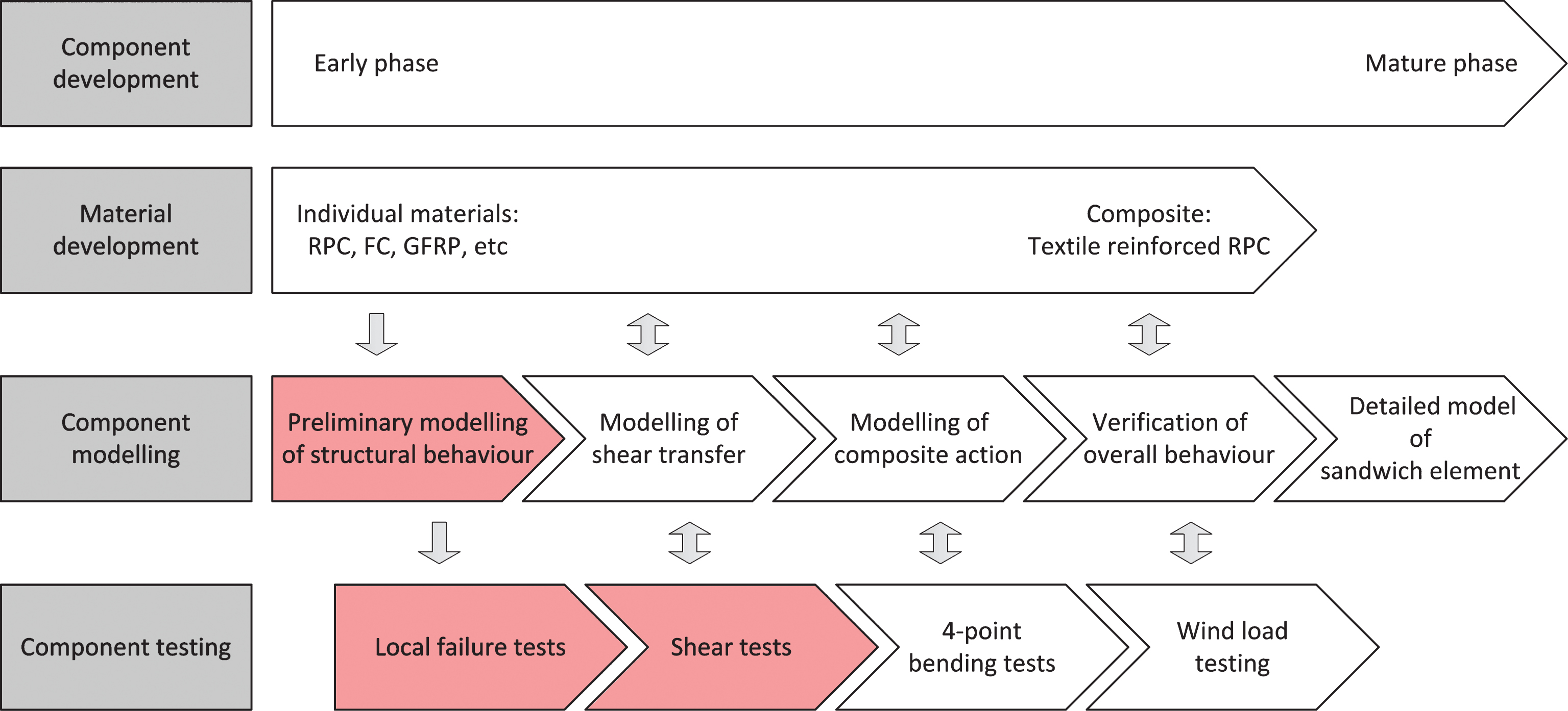
Fig.7
Illustration of conceptual sandwich element (left) and associated load model (right).
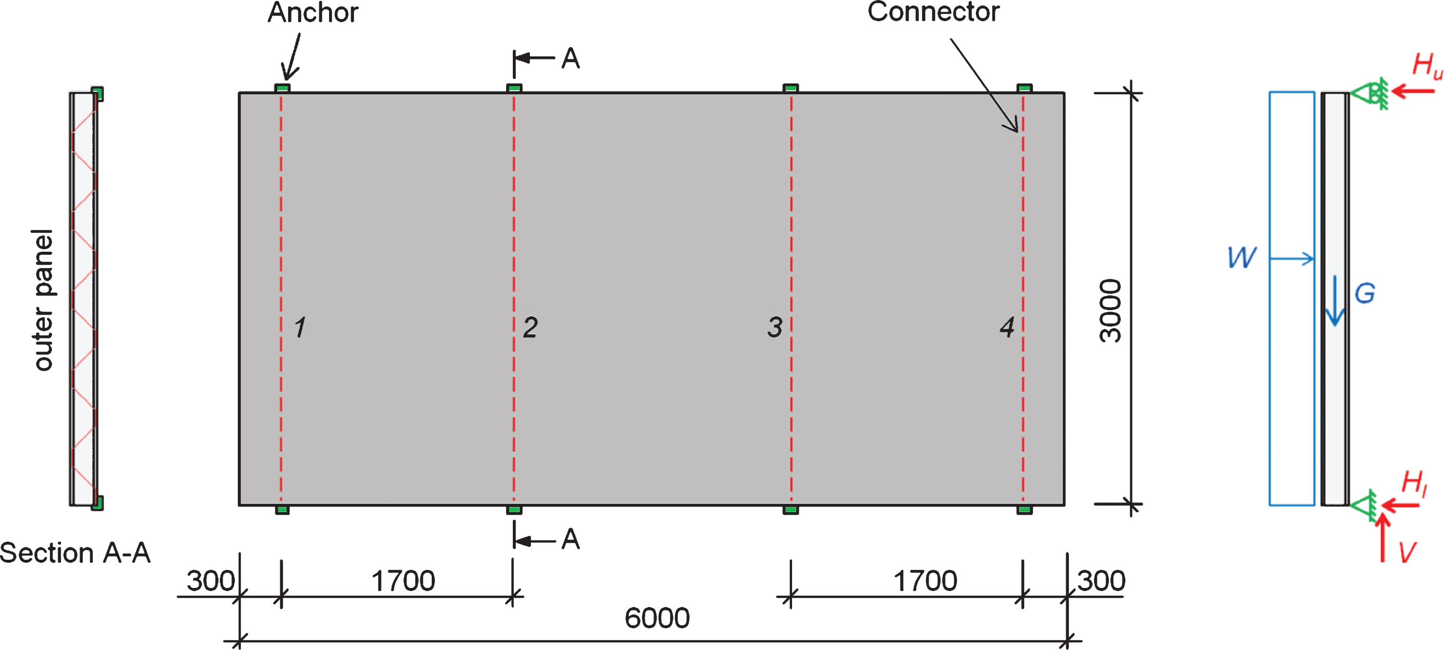
Fig.8
First preliminary structural FE model (left) and displacement plot of the element when subjected to a wind pressure of 1000 Pa (right). The maximum displacement in the middle of the element is about 1.3 mm.
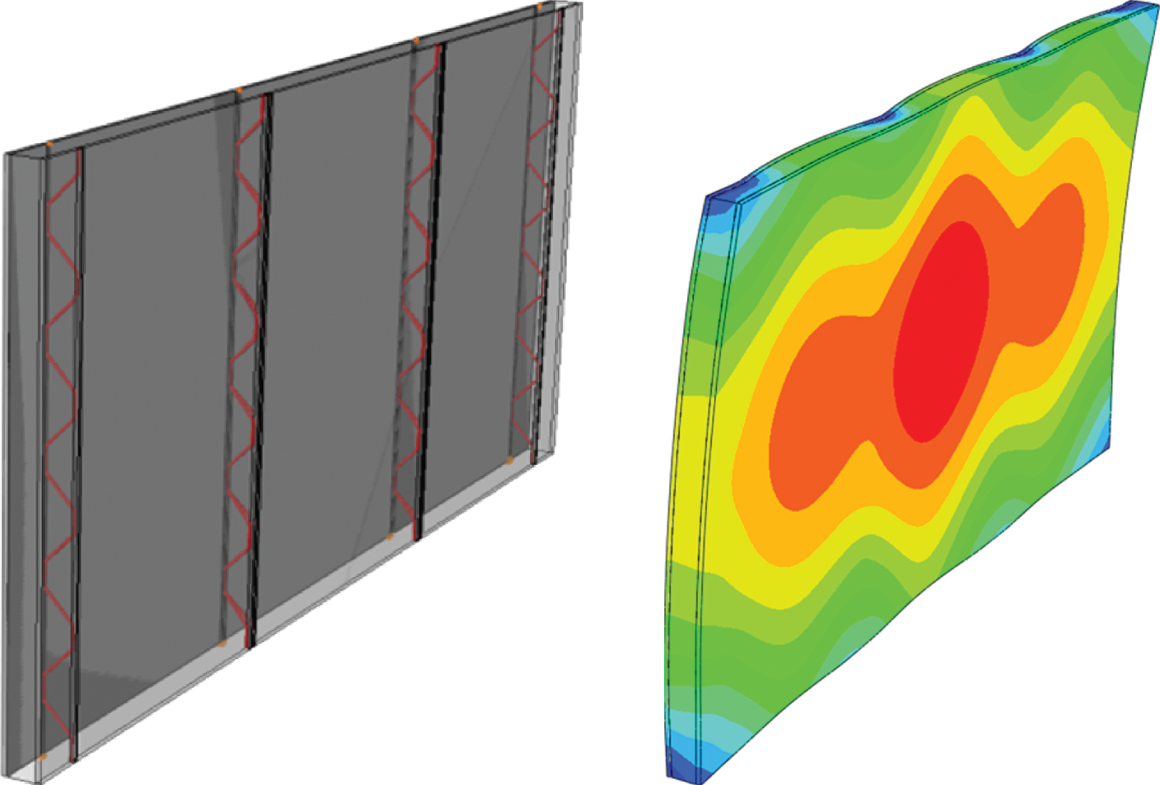
Fig.9
Photo (left) and illustration (right) of the local failure test setup.
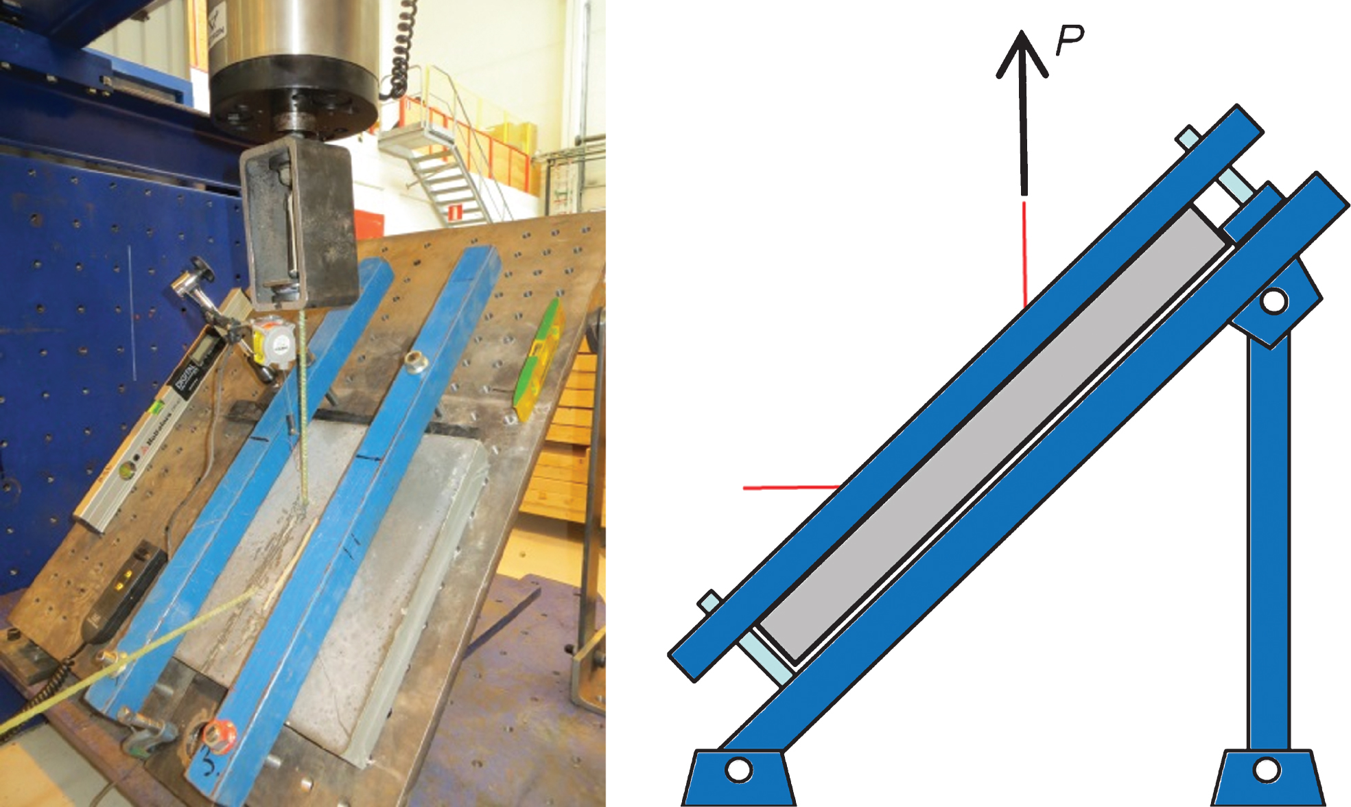
Fig.10
Schematic illustrations of the different configurations: steel connector (a); GFRP connector (b) and GFRP connector with build-up panel (c).
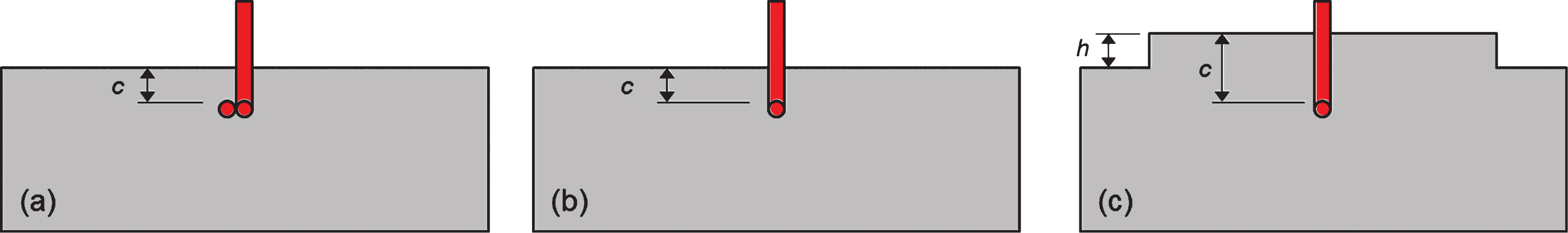
Fig.11
Pull-out capacity as function of embedment depth for steel connector, GFRP connector, and the build-up configurations with GFRP connector.
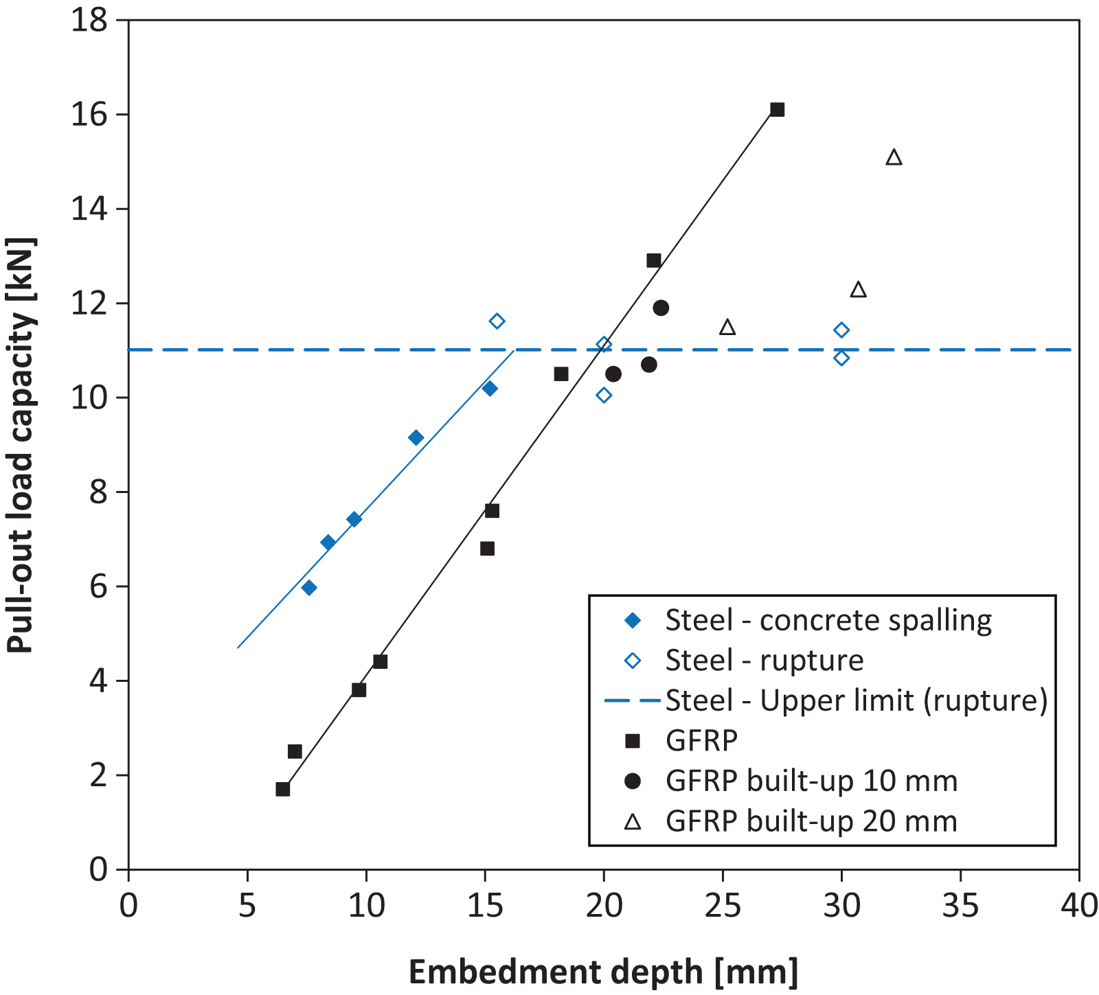
Fig.12
Photo (left) and illustration (right) of the shear test setup (red arrows indicate resulting reaction forces).
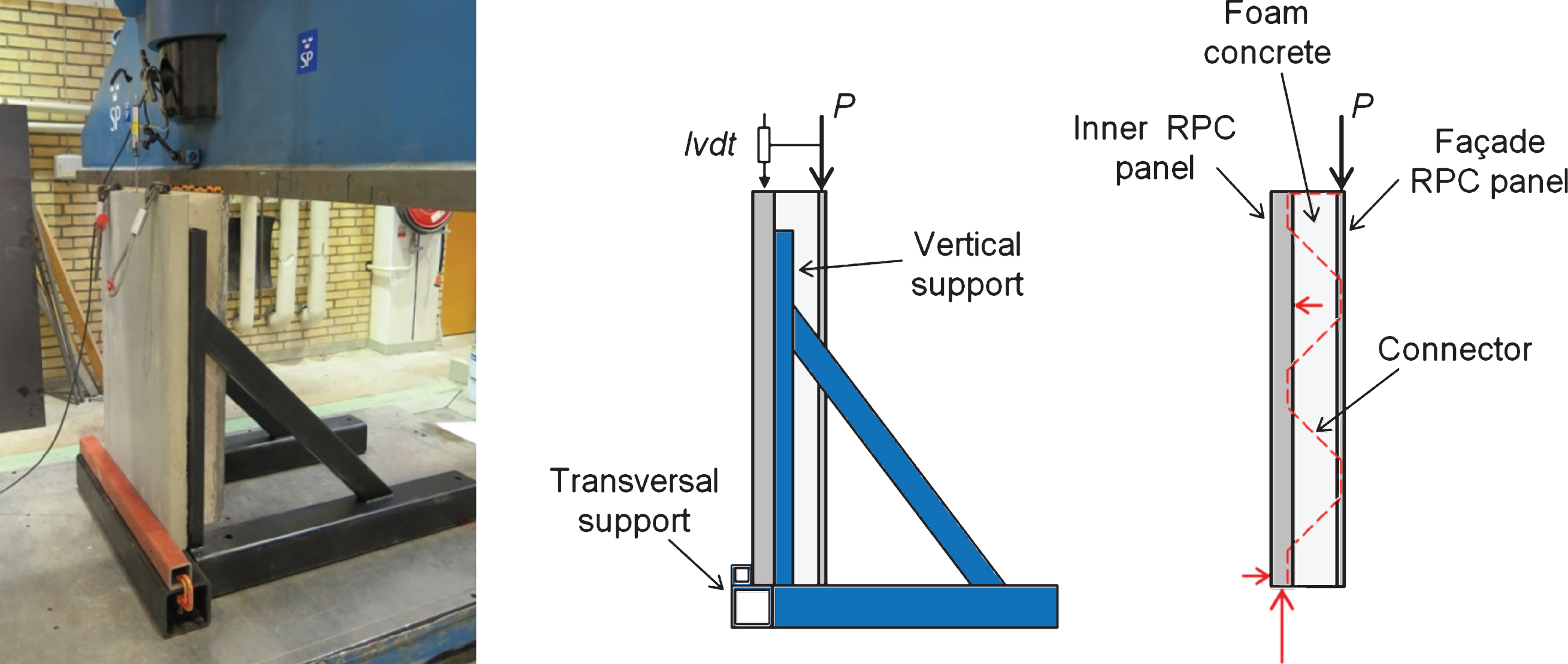
Fig.13
Schematic illustrations of the different configurations: steel connector (A); GFRP connector (B, C); GFRP connector with build-up panel (D); double GFRP connector (E).
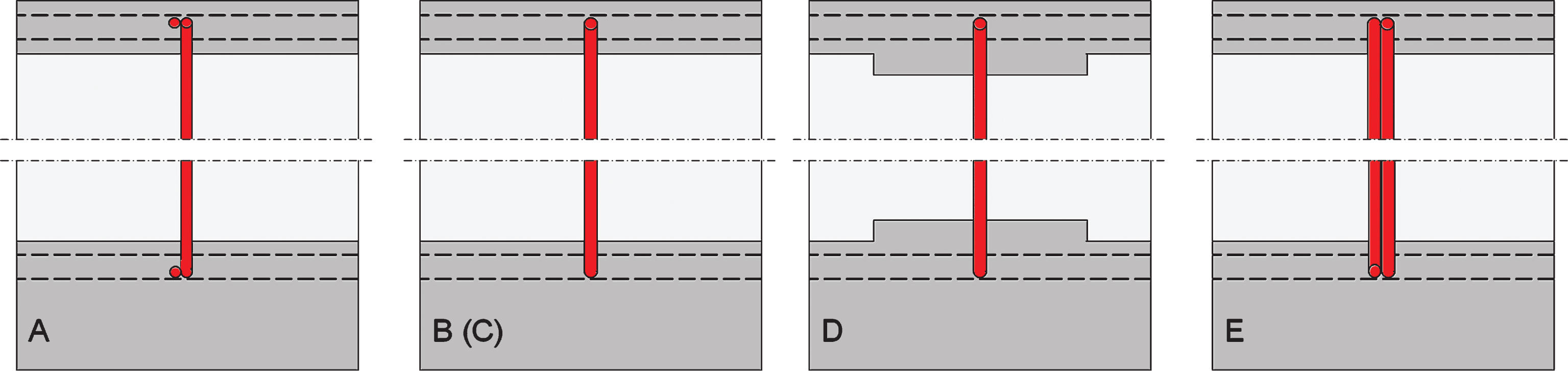
Fig.14
Single (left) and double (right) GFRP connector layouts.
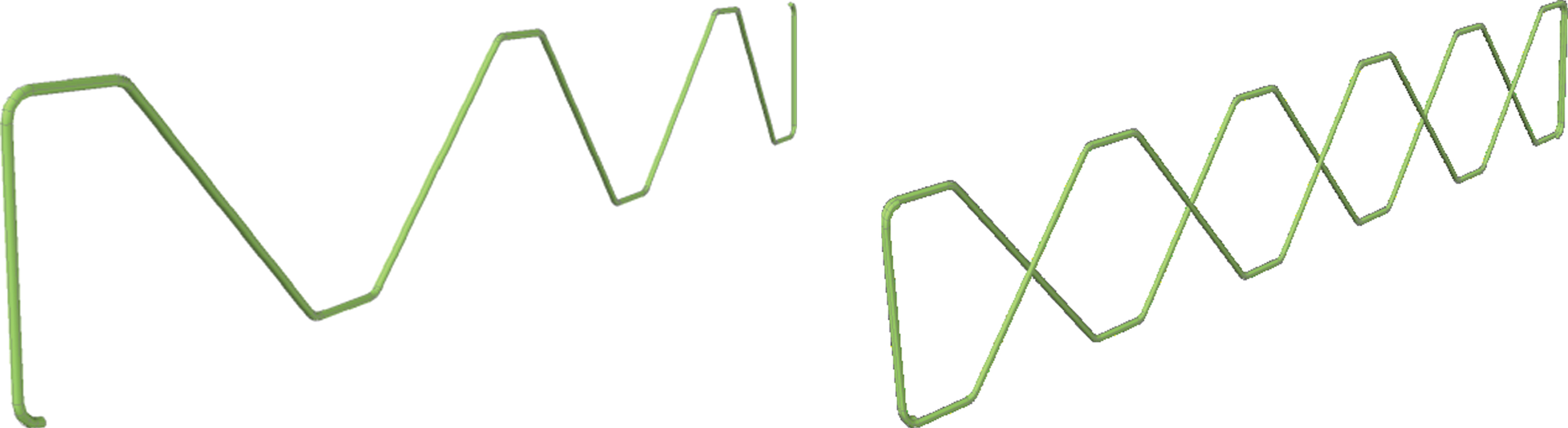
Fig.15
Load vs. relative shear displacement for steel connector (A) and the four GFRP connector configurations (B, C, D and E).
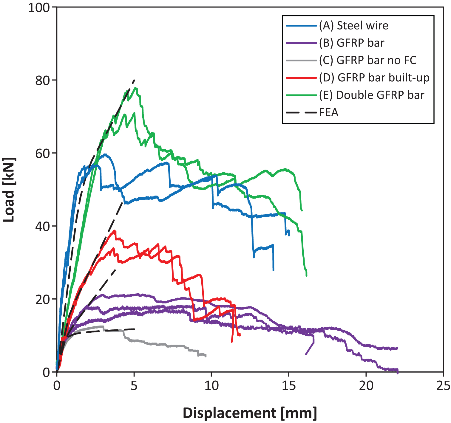
Fig.16
Section of the FE model for shear specimen with connector configuration B (left) and a displacement plot showing the buckling of the compressed connector bars (right).
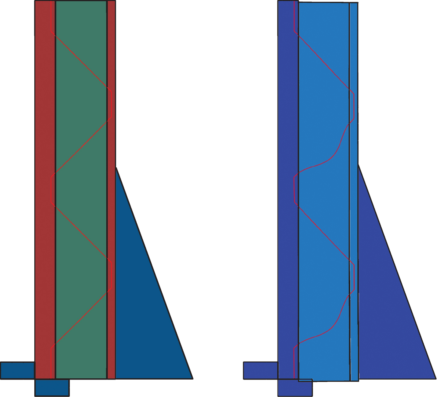
Table 1
Material properties used in the FE model
| Material | RPC | Foam Concrete | GFRP bar |
| Young’s Modulus (MPa) | 50000 | 10 | 40300 |
| Poisson’s Ratio | 0.2 | 0.1 | 0.3 |
| Density (kg/m3) | 2500 | 300 | 2000 |
Table 2
Summary of anchor reaction forces
| Anchor | Vertical reaction | Lower horizontal | Upper horizontal |
| location | force, V (kN) | reaction force, Hl (kN) | reaction force, Hu (kN) |
| 1 &4 | 5.3 | 1.9 | 1.5 |
| 2 &3 | 7.1 | 3.1 | 2.5 |

