An energy-active facade element from mineralized foam (MF) and micro-reinforced, ultra-high-performance concrete (mrUHPC)
Abstract
Today, an increase of the energy efficiency in the manufacturing industry is typically achieved by separate, parallel measures, primarily on the level of the individual machines. Energy efficiency can be improved by a holistic, integrated approach, which links the machines, the production process, the technical infrastructure and the building and its envelope. The subject of this paper is the development of a new prefabricated element for facades and roofs, which was developed and built in the context of a research project called ETA-Fabrik (i.e. energy-efficient factory, www.eta-fabrik.de) at TU Darmstadt, Germany. The element consists of purely mineral materials (concrete) and can be energetically activated by thin capillary tubes integrated in the surface layer. This surface layer consists of a micro-reinforced, ultra-high-performance concrete (mrUHPC) to achieve a low component thickness due to its high mechanical capacity, resistance against thermal changes, surface quality and low permeability. The core of the element is responsible for insulation. For this, a mineralized protein foam (MF) is used. It provides very good thermal insulation properties due to its eminently low density and thus allows low heat transfer coefficients. Therefore, the final facade element combines limiting, bearing, insulating and thermal activation using concrete.
1.Introduction
The energetic model of a typical factory set-up can be interpreted as shown in Figure 1. It is a complex system of different functions that are linked with each other and influenced by external parameters (Herrmann, Kara, Thiede, & Luger, 2010). Maximizing the energy productivity by increasing the product output only is no longer worthwhile for companies in the industrial sector. Therefore, within the coming years, productivity, energy and resource efficiency will have to be seen in connection and investigated with the product itself, thus combining the view on the product, the production process, its implementation by machines and workers and the building around it. A separate treatment and separate optimization of the different parameters typically leads to contradictions and imbalances. One example is that workers are frequently exposed to strong heat radiation next to machines with emission of waste heat. In addition to the unused heat losses, the low quality of work environment is another disadvantage leading to reduced productivity. A significant correlation of well-being at work with the quality of the final products was, for example, described by , Helbig & Ferreira (2005). Furthermore, typical building envelopes in industrial constructions are often composed of different energetically passive and active components in addition to building technology. Currently, there are only few examples that can respond intelligently to typical needs related to heat supply and heat reduction, e.g. switchable glazing or phase change materials (PCM). Today, an intelligent linkage of the energetic interdependencies shown in Figure 1 is lacking, probably also due to the strong interdisciplinary nature of the problem. From a structural point of view, the typical floor plans of factories must be flexible so that production processes have the potential of change. This requires large areas to be covered with construction elements that are relatively light in relation to their span. The structures should be buildable in a short time and should be cheap, usually ignoring architectural identity and thermal behaviour inside the factory. For these reasons, building envelopes today usually consist of several components and layers according to their functions: bearing and limiting. Thermal behaviour and energetic activation are often ignored or of lower interest. This approach leads to multiple interfaces and complex joining techniques. Moreover, with this separation, a holistic assessment of resources is often difficult.
2.The energy efficient factory (ETA-Fabrik)
Within recent years, law in Germany has gradually restricted the allowable heat energy demand and the permissible heat loss from buildings. In addition, the non-renewable energy consumption in building operation for new buildings should be reduced to zero by 2020 according to an EU-directive (Bundesministerium für Wirtschaft und Technologie, 2005). In contrast to the housing sector, industrial buildings should usually meet two typical requirements of production processes: on the one hand, the above mentioned variability of the plant and, on the other hand, an associated variability in the electrical and thermal energy supply. Often, a significant excess of thermal energy is the result of this variability and the result of a lack of holistic designing; therefore, the transfer and re-use of this energy will be considered in the project ETA-Fabrik. ‘ETA’ stands for energy-efficient factory for interdisciplinary and applied research. It is part of the 5th Energy Research Program of the German Federal Government ‘Innovation and New Energy Technologies’ by the Federal Ministry of Economics and Technology (BMWi). The topicality of the project is demonstrated by the participation and support of many industrial companies, both directly participating in the research project as well as acting as advisors in an additional working group. By this, a direct internal and external transfer of knowledge shall be guaranteed. Within the project, a 1 : 1 scale model factory is being built on the campus of the TU Darmstadt in 2016 (Fig. 2). A production process chain, which is typical for the German medium-sized metal processing industry, will be installed in this model factory containing chipping, cleaning and heat treatment (Fig. 3).
Previous research at the Institute of Production Management, Technology and Machine Tools (PTW) at the Faculty of Mechanical Engineering at TU Darmstadt has been successfully aimed at an isolated energy optimization of individual machines, resulting in 40% –50% in energy savings compared to conventional machines. Additional savings of about 30% are already identified for an isolated optimization of the production process, 25% for an optimization of the building and its envelope and 20% for the technical infrastructure (Fig. 4). The research project ETA-Fabrik at TU Darmstadt, however, with its holistic approach aims at 40% energy savings compared to conventional manufacturing factories. This shall be achieved by a suitable energy concept, an appropriate energy management with energy-efficient operation and architectural and structural measures. For this holistic approach, the energetic interaction of the building envelope, the environment, the technical infrastructure and the production process chain must be carefully analysed and optimized. One important idea is the thermal activation of the building envelope in combination with thermal storages to allow heating and cooling of the factory. It must be noted that contrary to the housing sector, in Germany, cooling during summer time is one of the important issues in many factories. Beside plants for metal processing industry like in this research project, the concept can be adapted to any kind of process with waste heat emitting machines, e.g. automotive industry, food industry, chemical industry. However, requirements on heating, ventilation and air conditioning for non-residential buildings has been increased in Germany for the last years, thermal activation of wall and roof elements becomes more interesting for any kind of industrial plants, because for using this technique, no high temperatures are necessary (12°C to 17°C for cooling and 30°C to 40°C for heating are sufficient).
3.The building envelope as part of the energetic concept
The building envelope can play an important part to influence the thermal exchange and allow energy optimization in energy-intensive production processes. Environmental energy from sun radiation and thermal energy from the process chain can be collected and fed into the system according to their suitability to allow an optimal (re-)use according to Figure 5. Moreover, cooling and heating by using the building envelope instead of energy-intensive air conditioning system units can further increase energy efficiency and also the well-being of the workers.
For cooling the factory interior, cool water passes through a fine and near-surface capillary network (Fig. 11) in the inner layer of the facade element, and cooling effect takes place. The gained heat can be used for a suitable step in the production process. It was shown by simulation with TRNSYS, that a cooling capacity of 60 kW is necessary for the production area (Fig. 6). If required during the winter period, the ambient air may be heated through the capillary network in the sense of a panel heating, using the stored energy in water tanks or the waste heat of the machines directly. Therefore, a heating capacity of 40 kW is required in reference to Figure 6, and is being charged from solar heat or from cooling of the machines or the room. Similar to conventional solar thermal systems like flat plate collectors or evacuated tube collectors, solar radiation present at the outside surface is being absorbed by the concrete and transferred to the capillary system. Such a system can also collect the outside environmental energy due to the temperature difference between ambient air and surface temperature. For this principle, a cascaded energy storage (water tanks at different temperature levels), and an intelligent operation of the associated process chain and machinery components are required. Two different kinds of water-filled thermal storages are used in this concept. For the high temperature level (80–95°C), which is connected with the cleaning- and heat-treated-machines, a vacuum super insulated heat storage with a volume of 15 m3 is used. For the medium and low temperature level (30–45°C and 12–20°C) as well as for the outer capillary tube system, three water storages made of high volume fly-ash concrete, with a volume of 25 m3 for each one, are used. Through its high content of fly-ash and its stability against leaching, no more coatings of the storage walls and floors are necessary. The storages are useful in any case while two or more processes are running dephased, so no consumer can use the thermal energy that was provided by a generator (e.g. the heat-treatment machine), especially during the transition period.
At the outside of the facade and roof elements, the same capillary network can be used to cool down warm water heated from the production process. Passively, this occurs whenever the temperature level of the outer surface is above the temperature level of the outdoor air. However, if this temperature gradient is not enough, a demand-dependent sprinkler system on the roof leads to an evaporation of water, which causes a high heat transfer coefficient. In this way, the thermal storage can be quickly discharged, for example in the transition from the cold to the warm season, in that case in order to use it for cooling of the interior or the machines.
In addition to the integrated active thermal system, a classical passive thermal insulation must be provided. A centre core of the facade element with good thermal insulating properties is made out of mineralized foam. By using this cement-bonded insulation material, all layers of the wall are basically built from the same material: concrete. Thus, among other positive effects such as non-flammability a sustainable overall life cycle from production to disposal is guaranteed.
4.Structure, layout and materials of the facade element
4.1.Structure and layout
The goal of the development is an integrative structural facade element, which combines all properties of individual facade components today, adding thermal activation:
The energetic interaction of the building envelope and the production process require cladding elements on the roof and facades, a rapid thermal activation and a high reactivity of its individual system components. In terms of sustainability and variability of the entire building, a homogeneous material composition is sought in view of production and disposal. To fulfil all these requirements, concrete is particularly suitable, because a structural and energy-optimized geometry can easily be achieved, the installation of the required capillary tube network is possible, fire protection issues can be addressed easily and the surface can be designed architecturally attractive. Beyond that, concrete is available easily and almost everywhere.
At the project start, the best combination of structural system and cross-section with regard to structural behaviour, ecology and economy had been searched by different kind of calculations: in a first step, 20 different static systems for hall constructions were analysed structurally by FEM under the existing spans and under unit loads. Those were compared with various static and constructive criteria like the amount of reinforcement and the complexity of joining for example (Fig. 7). Then 41 combinations of static systems and cross-sections, like beams, plates and T-beamswere analysed structurally, constructively (e.g. resistance against bending, shear, torsion and stability, transportation), ecologically (e.g. life-cycle analysis) and economically (cost out of quantity determination) (Fig. 8). At last the three best combinations from structural systems and cross-sections were chosen and a detailed economic analysis, which considered costs for production, mounting and transport as well as a sustainability analysis based on DGNB criteria, was done. A concluding comparison provided the best combination of structural system and cross-section with regard to structural behaviour, ecology and economy. This combination was finally built for the ETA-Fabrik.
Figure 9 shows a layout of such an element for roofs and facades of industrial buildings. The built-up consists of an inner structure from pre-fabricated double-web concrete slabs including a capillary tube network at their inside, which is connected to two outlying pipes for flow and return in order to regulate each element individually and to disconnect the element if it will be necessary. Due to their geometry, these slabs combine the characteristics of carrying and providing a formwork for the mineralized foam. Pre-stressed concrete elements in the shape of a saddle roof are used for the roof. Those provide a uniform rib structure inside the building (Fig. 10). Slender and thus more economical cross-sections regarding the web width and the web height can be achieved compared to additive systems of trusses, purlins and roof slabs. By a shear stiff coupling of several elements in the plate area, the slabs can easily be used for the bracing of the factory building in longitudinal direction. In transversal direction, the elements are fixed in the foundation, thus there is no need for a secondary bracing.
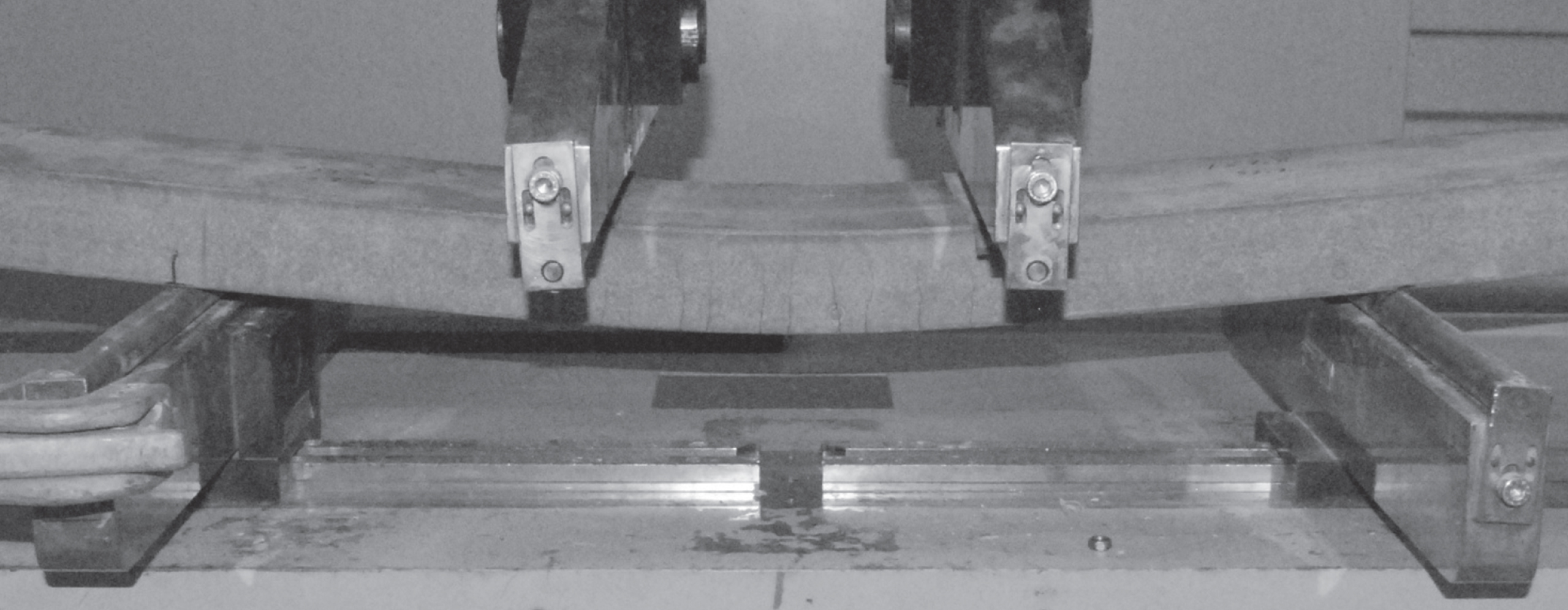
In a second step, the mineral foam with a thickness of about 25 cm to 40 cm is installed on the hardened pre-fabricated component. Very thin micro-reinforced, ultra-high-performance concrete (mrUHPC) panels including a capillary tube network connected to two outlying pipes are used on the outside. Those are connected to the wall-slabs by special facade anchors, which consist of a new developed screw and nut combination made from stainless steel. The latter is a 2 mm thick perforated plate with a diameter of 8 cm and a welded internal thread for screws M 16. The plate is located 2.5 cm under the panel surface and helps to spread the punctual forces in the cross-section by activating the micro-reinforcement. Therefore the resistance against concrete collapsing grows and the failure mechanism changes from concrete to steel. On the roof, load picked-up spacers, based on spacers for double floors, consisting of stainless steel pipes in combination with vertically adjustable bearings are used. Due to high mechanical and thermal resistance of mrUHPC, the dimensions of the panels can be very large and they are economically installable with a thickness of only 3 cm to 5 cm. In the research project ETA-Fabrik, the panel dimensions are 10 m×1.50 m and a thickness of 5 cm is planned. The capillary network consists of a fine tube system filled with antifreeze and water, which is demineralized in order to avoid clogging up with impurities. The dense arrangement of pipes with an inside diameter of approximately 3 mm (Fig. 11) and the installation in the surface layer of the thermal highly conductive mrUHPC lead to the high necessary thermal dynamic of such a system, which distinguishes it from the conventional systems with an activation of concrete elements, and acts as a large heating or cooling surface that can react quickly to the needs of air-conditioning equipment. To demonstrate that, an outside test station with two kinds of facade panels made of mrUHPC was installed. It could be shown by trial and using the finite element method (FEM) that the cladding panels can heat up to 14 K within twenty minutes, and the temperature distribution in the cross-section is almost constant (Fig. 12) by a flow rate of 0.5 m/s, which leads to a laminar flow in the pipes. It was also possible to do a non-steady simulation with FEM in a timespan of one day. The resulting values were very close to the values resulting from the measurements (Fig. 13).
4.2.Materials
Beside the described thermal activation, the new development for the insulation uses special cement-bound protein foam, called mineralized foam (MF, Fig. 14). Very good thermal insulation effects with low thermal heat transfer coefficients can be achieved depending on the obtained density. It is bound with cement or a mineral cement replacement. The material has a dry density of 200 kg/m3 and a related thermal conductivity λdry of about 0.06 W/(mK). Mineralized foam is not flammable and therefore also suitable for use in places with increased fire protection requirements. In contrast to similar insulation boards made of aerated concrete, the material used here hardens in the air and autoclaving is not necessary. In addition to the absence of this manufacturing step, it is possible to bring the fresh foam material to the surface-hardened concrete components in a precast concrete plant. Contrary to the usual limitations of the cellular concrete production, components can thus be manufactured with almost any desired dimensions. The formulation of the binder matrix is optimized with the aid of additives that have a low input of primary energy. Moreover, through research at TU Darmstadt, a composition of the binder stone was developed which uncouples a desired minimization of heat transfer by conduction and density reducing of the mineralized foam up to a certain level. While retaining low thermal conductivity, a required minimum strength of 0.4 N/mm2 can be ensured.
A substantial requirement for implementation of the described concept is a construction material that can resist substantial thermal and hygric loads in addition to high static loads. Furthermore, the material must allow the integration of the capillary tubes, and should have as little resistance as possible against thermal-energy flow through high thermal conductivity in order to enable thermal activations of the surface layer. This can be achieved by high-strength and dense concretes with micro-reinforcement (Fig. 15). The sd-value of UHPC, the factor to quantify the water vapour density of a material, is about 45 times larger than the sd-value of normal concrete (Reineck, Greiner, Reinhardt, & Jooß, 2004). In a facade component, the mrUHPC concrete offers high potentials for large elements in terms of its strength parameter. Bending strengths of more than 35 MPa as well as compression strengths of more than 115 MPa can be achieved. This results in a low component thickness. From a structural point of view, panels with a thickness down to 1 cm could be used. However, the installation of the capillary tube network, the manufacturing method and the tests for durability do not permit this.
5.Conclusion
Energy efficiency in production is an important current topic in industrial processes. An optimization cannot be successful if only individual solutions are considered. Only a holistic approach including the machines, the production process, the technical infrastructure and the building envelope can significantly increase energy efficiency. This will be shown by the model factory ETA-Fabrik at TU Darmstadt which is being built in 2016.
In this context, thermal activation of facade elements seems to be promising to link the elements with the energy network, to make use of low temperature energy losses within the production processes and to allow cooling of factories without energy-intensive cooling units.
The element shown here is realized by purely mineral materials (concrete) and can be energetically activated by capillary tubes integrated in the surface layers. These surface layers consist of a micro-reinforced, ultra-high-performance concrete (mrUHPC) to achieve a low component thickness due to its high mechanical capacity, resistance against thermal changes surface quality and low permeability. The core of the element is responsible for insulation. For this, a mineralized foam (MF) was developed. It provides very good thermal insulation properties due to its eminently low density (dry density about 200 kg/m3, thermal conductivity λdry about 0.06 W/(mK)). The newly developed element for facades and roofs combines limiting, bearing, insulating and thermal activation by using concrete. For the future, the structural capacity reserves of the UHPC within such elements should be activated to further reduce the element thickness. For this, research on the structural stability and the respective influence of the concrete shrinkage should be initiated. This includes also a development of foam production and mrUHPC mixture.
References
[1] | Abele E. ((2012) ). Skizze des Forschungsprojektes η-Fabrik. TU Darmstadt. |
[2] | Beka Heiz- und Kühlmatten GmbH ((2013) ). BEKA CD-ROM. Produktordner und Berechnungsprogramme, p. 15. |
[3] | Bundesministerium für Wirtschaft und Technologie ((2005) ). Innovation und neue Energietechnologien. Das 5. Energieforschungsrahmen-programm der Bundesregierung. |
[4] | Herrmann C , Kara S , Thiede S , & Luger T. ((2010) ). Energy Efficiency in Manufacturing – Perspectives from Australia and Europe. In: Proceedings of the 17th CIRP International Conference on Life Cycle Engineering (LCE2010), Hefei, China (pp. 23–28). |
[5] | Landau K , Helbig R , & Ferreira Y. ((2005) ). Ergonomie am Arbeitsplatz. In Eisele J. , & Staniek B. (Eds.), Bürobau Atlas, Grundlagen/Planung/Technologie/Arbeitsplatzqualitäten, (pp. 208–217. Callwey-Verlag (Hrsg.). |
[6] | Reineck K.-H , & Greiner S. ((2004) ). Dichte Heißwasser-Wärmespeicher aus ultrahochfestem Faserfeinkornbeton. Forschungsbericht zum BMBF-Vorhaben 0329606V, p. 82. Institut für LeichtbauEntwerfen und Konstruieren (ILEK), Universität Stuttgart. |
[7] | Thumm F. . ((2013) ). Simulation zur Bestimmung des Energiebedarfs der Halle. TU Darmstadt, 2013. |
Figures and Tables
Fig.1
Energetic model of the factory, translation after Herrmann et al. (2010).
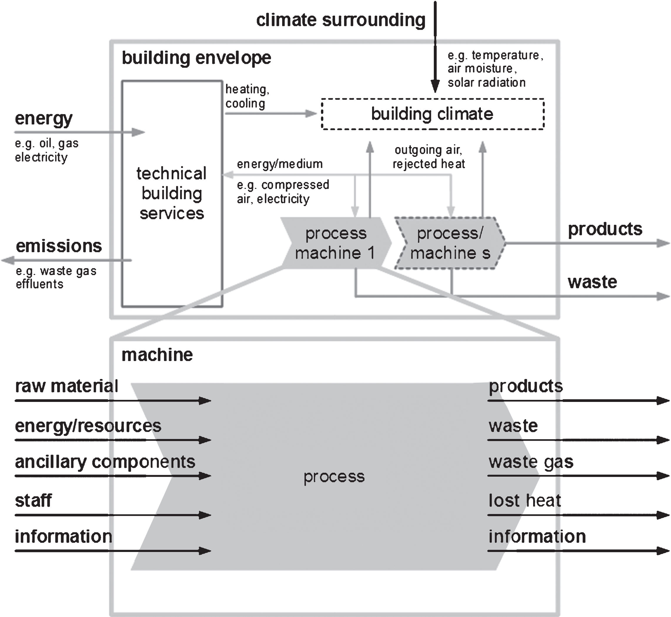
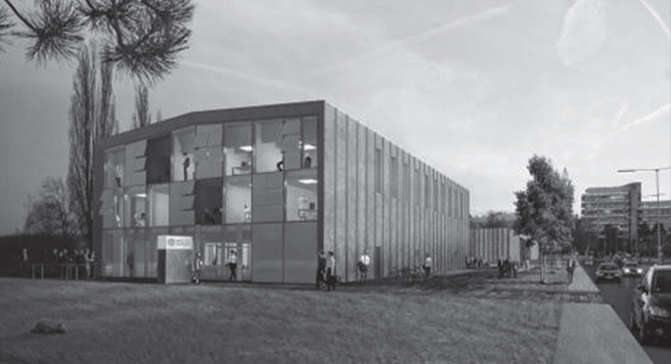
Fig.3
Process chain for the production of a tax disc for hydraulic pumps, translation after Abele (2012).
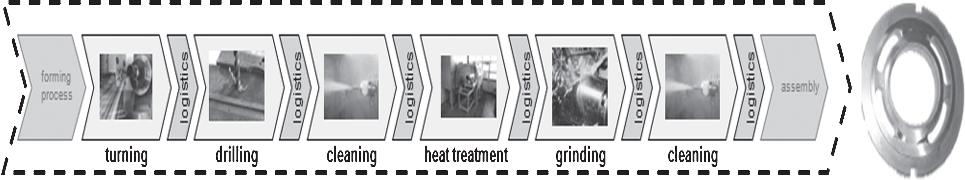
Fig.4
Estimation of the potential savings in a holistic view of industrial production, translation after Abele (2012).
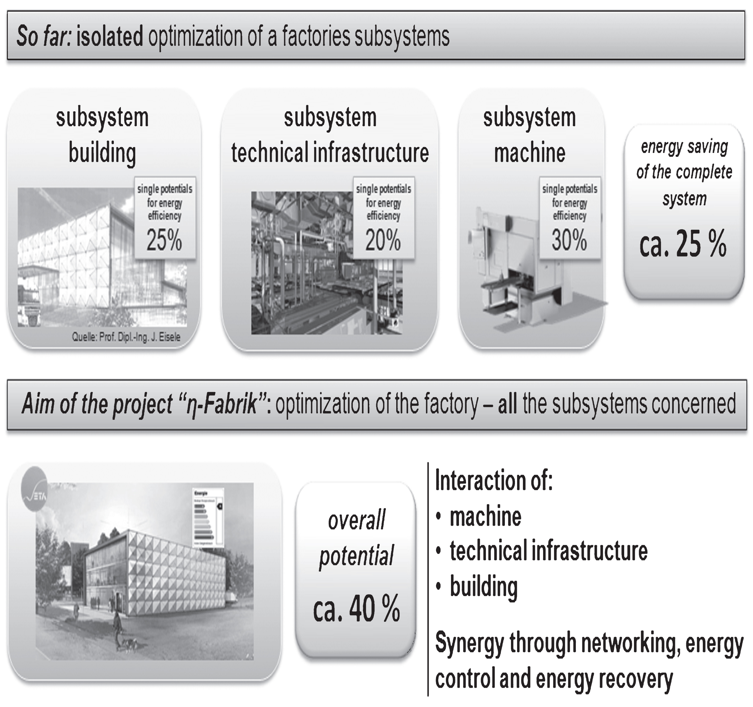
Fig.5
Energy concept for cooling and the use of waste heat from the production operation in the summer (Abele, 2012).
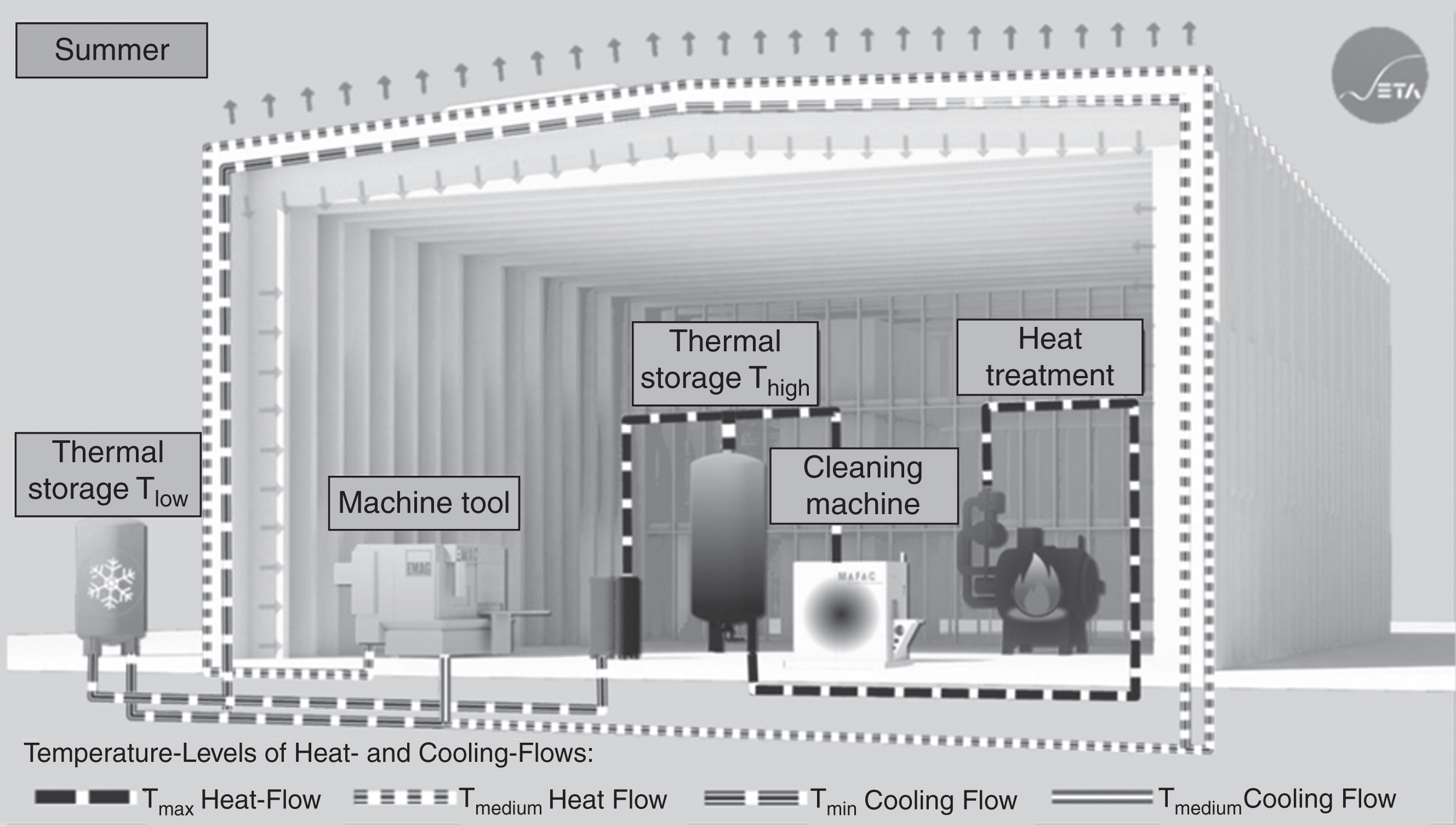
Fig.6
TRNSYS-simulation of heating and cooling capacity in relation to outdoor temperature based on a production process with a three-shift operation and an average power consumption of all machines of 83 kW (Thumm, 2013).
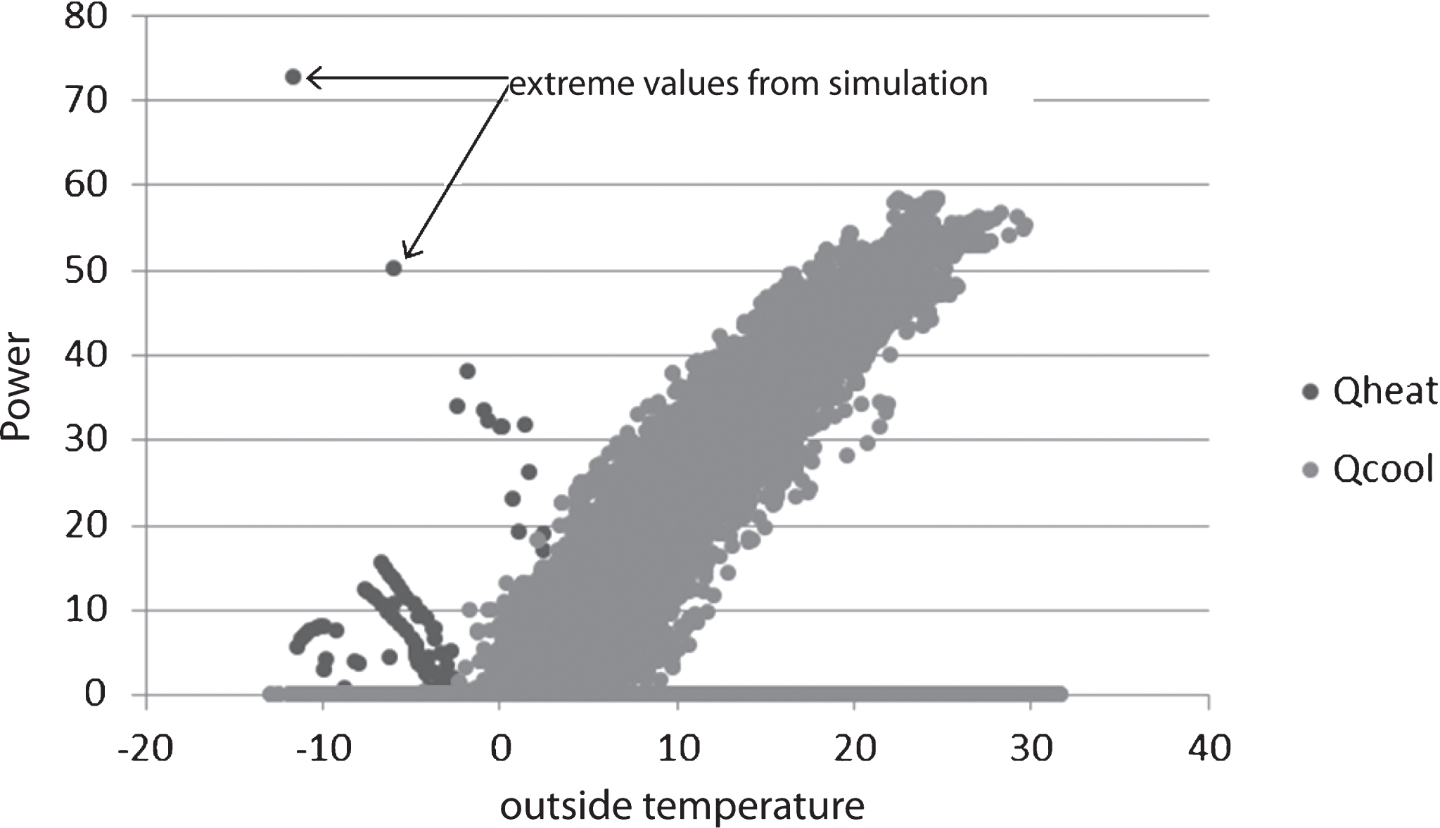
Fig.7
Evaluation of different structural systems (extract).
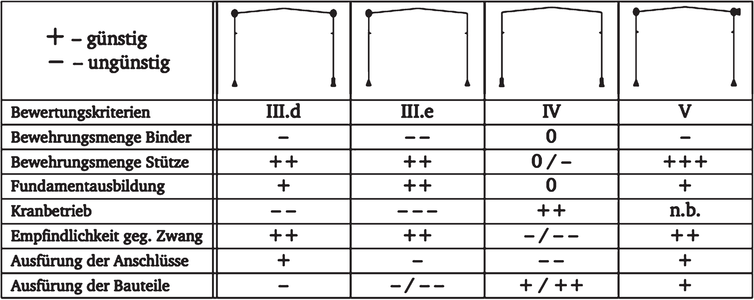
Fig.8
FE-Model of one combination of structural system and cross-section and primary energy of all 41 combinations after life-cycle analysis according to DIN EN ISO 14040 and DIN EN ISO 14044.
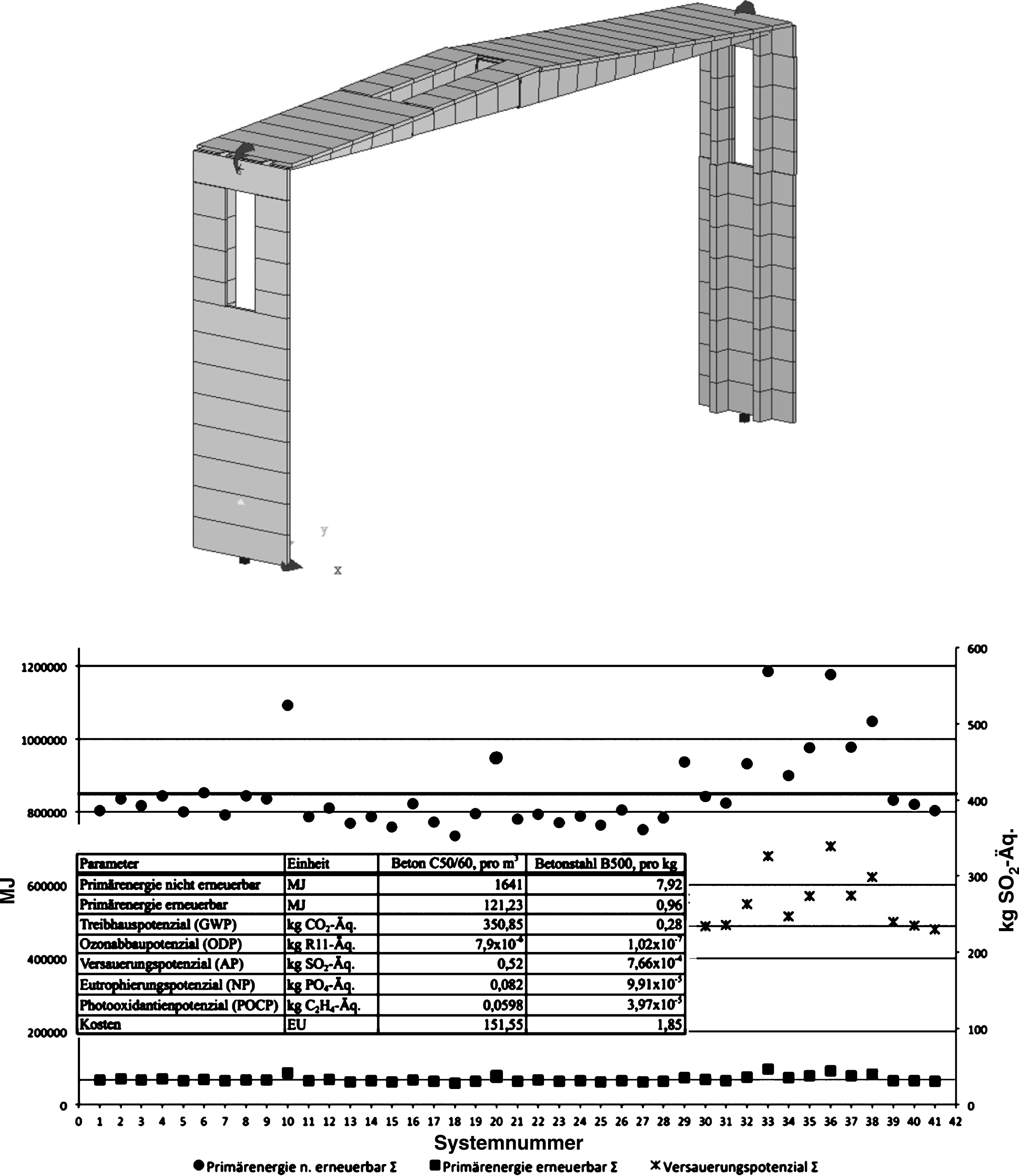
Fig.9
Roof and facade element from concrete components.
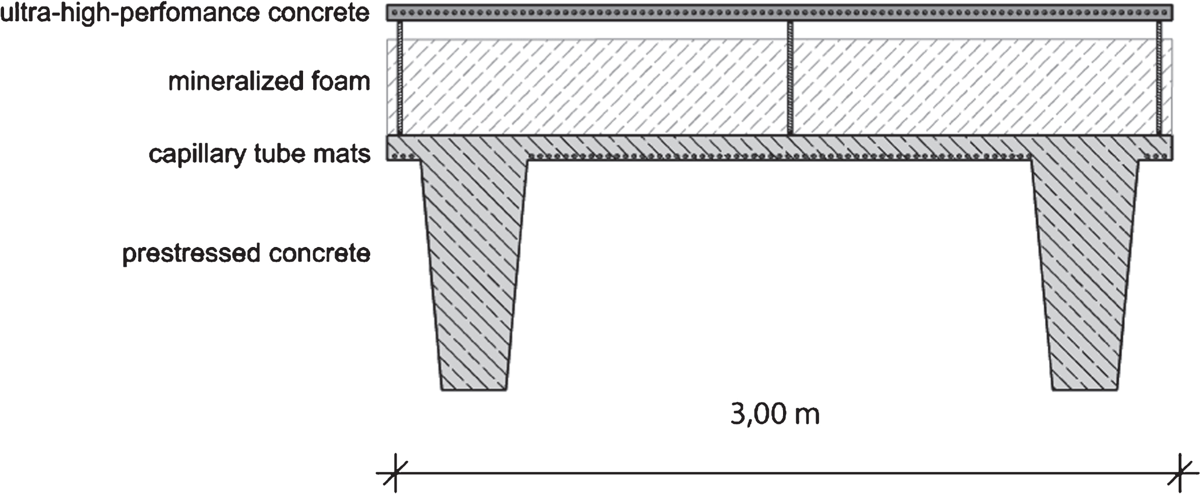
Fig.10
Interior view of the rib structure of the industrial hall.
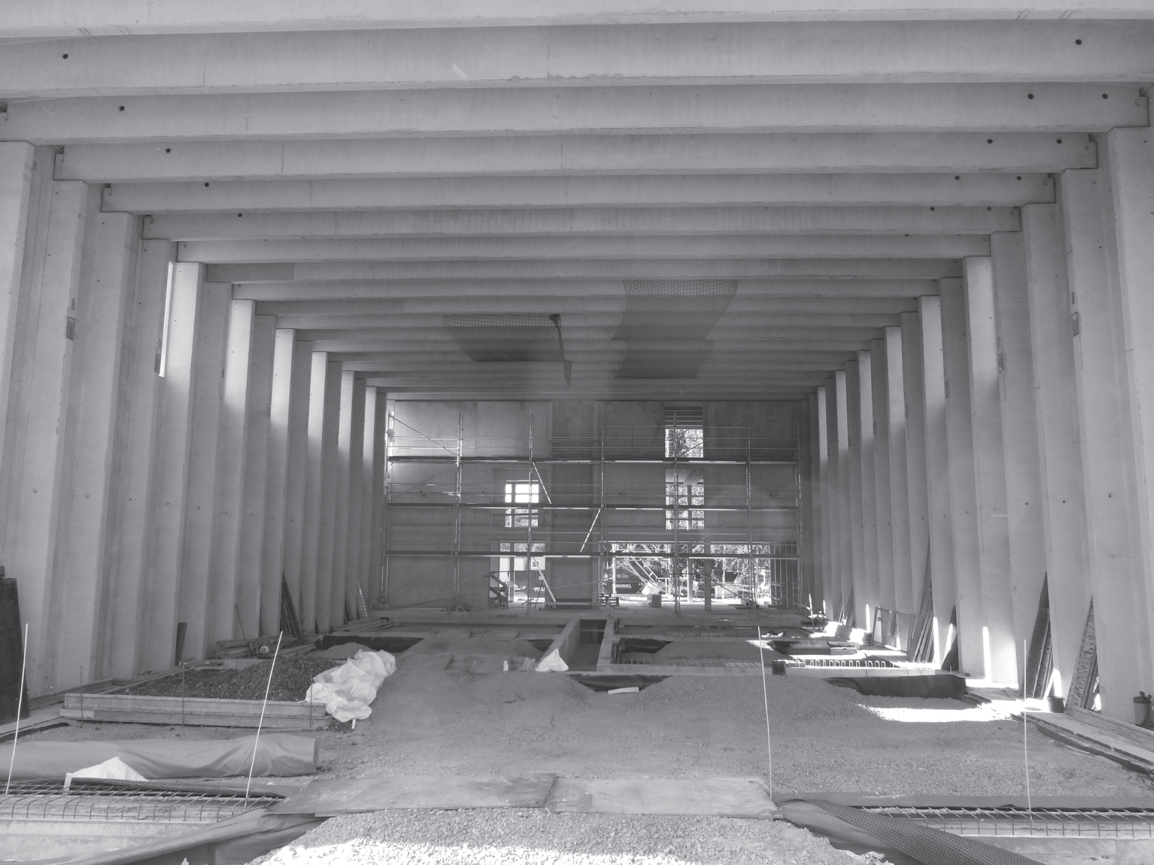
Fig.11
Exemplary element of capillary tubes used in the ETA-Fabrik, translation after Beka Heiz- und Kühlmatten GmbH (2013).
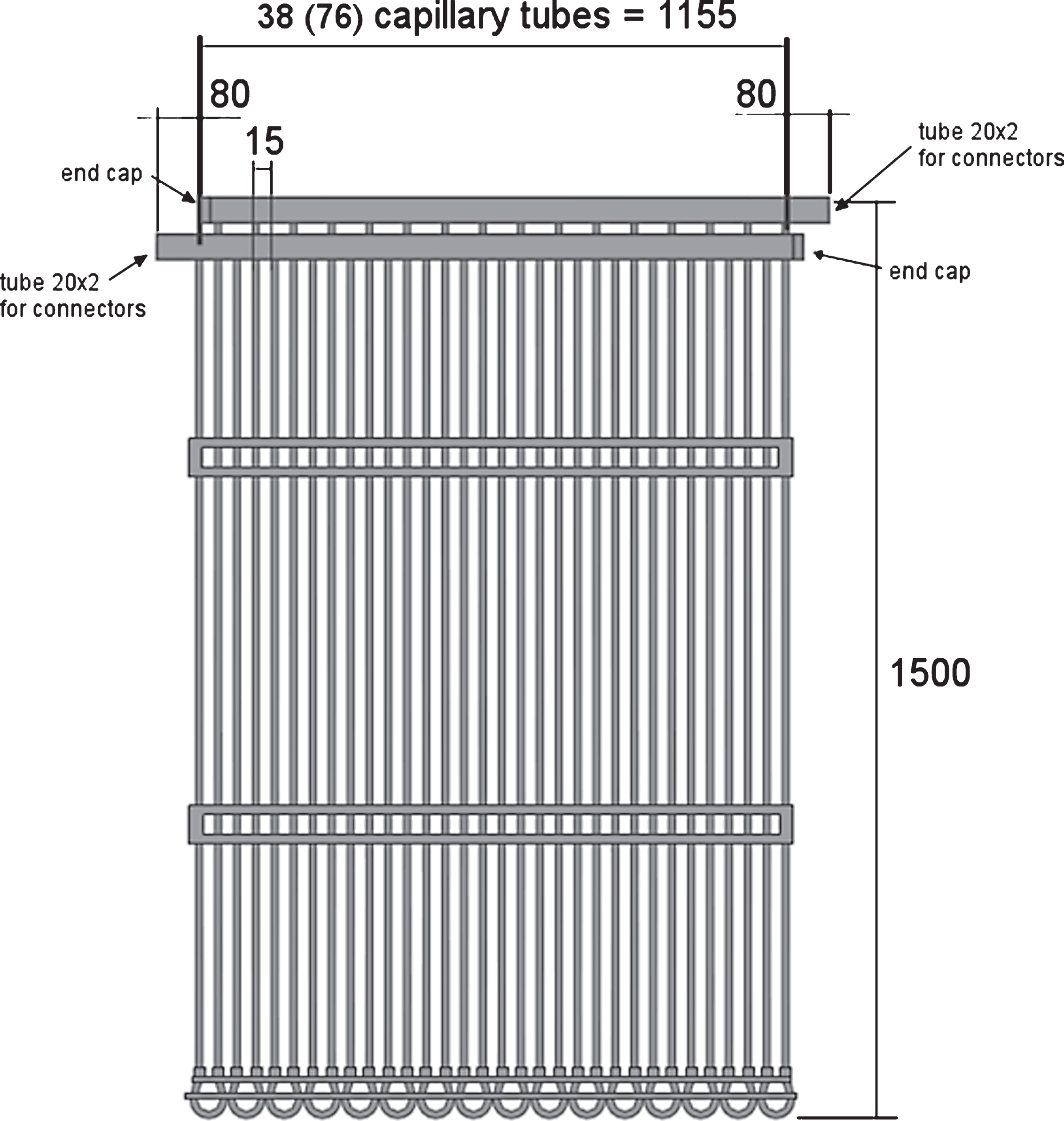
Fig.12
Heating-up time of a facade panel from mrUHPC.
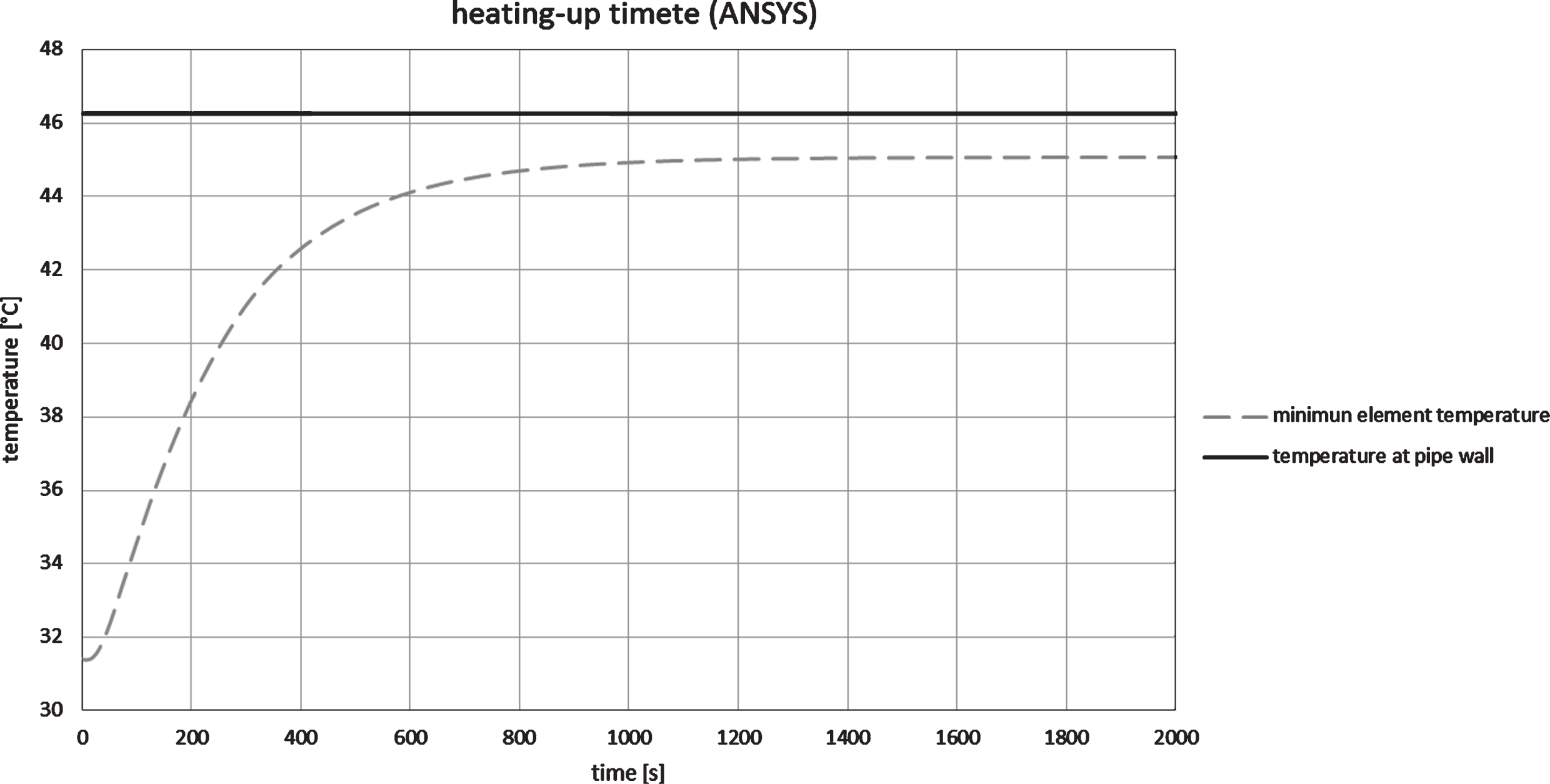
Fig.13
Non-steady temperature distribution in a thermal activated building element. Measurement data from IWB, Universität Stuttgart.
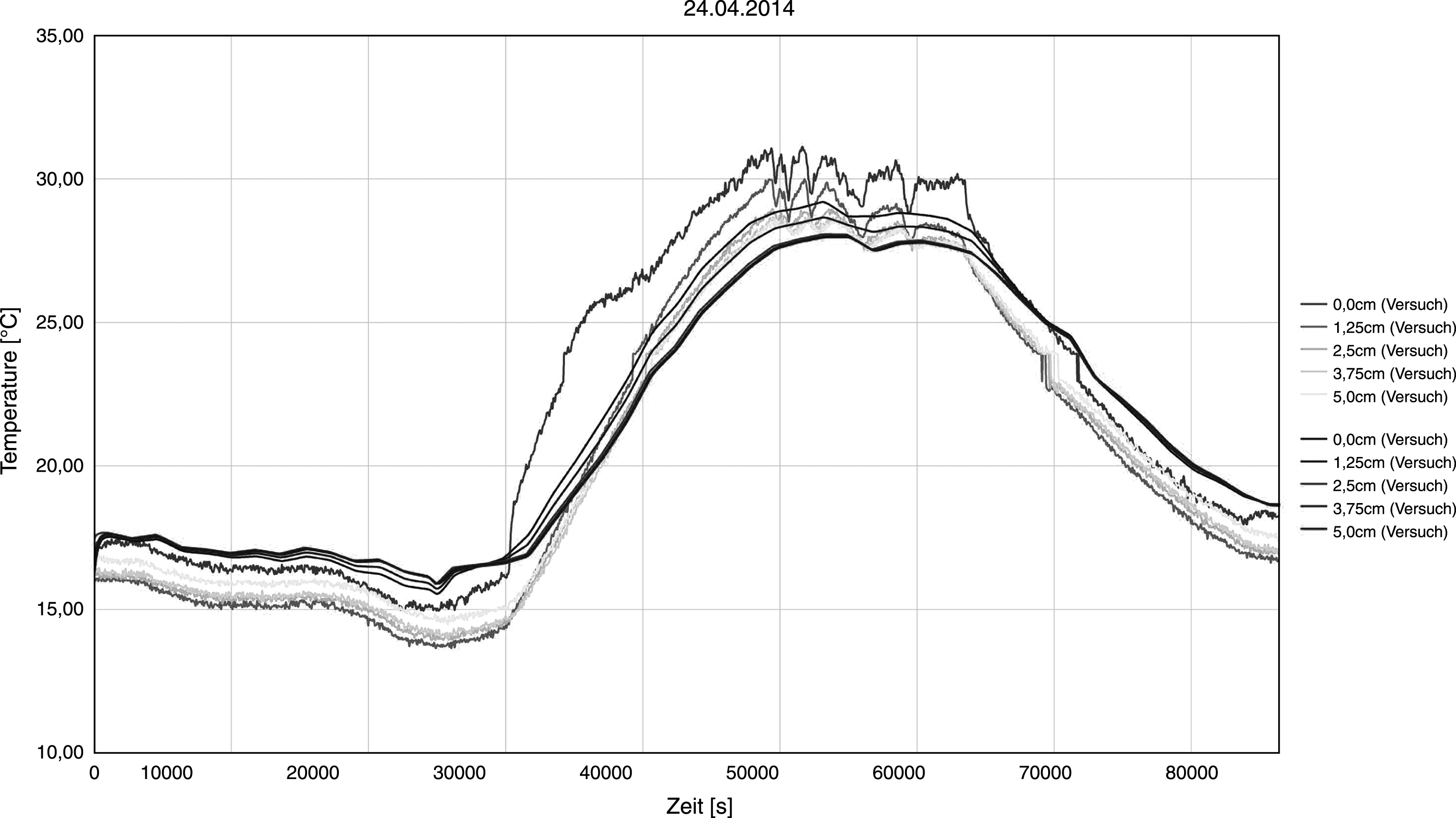
Fig.14
Facade panels made of UHPC (left), insulating layer of mineralized foam (right).
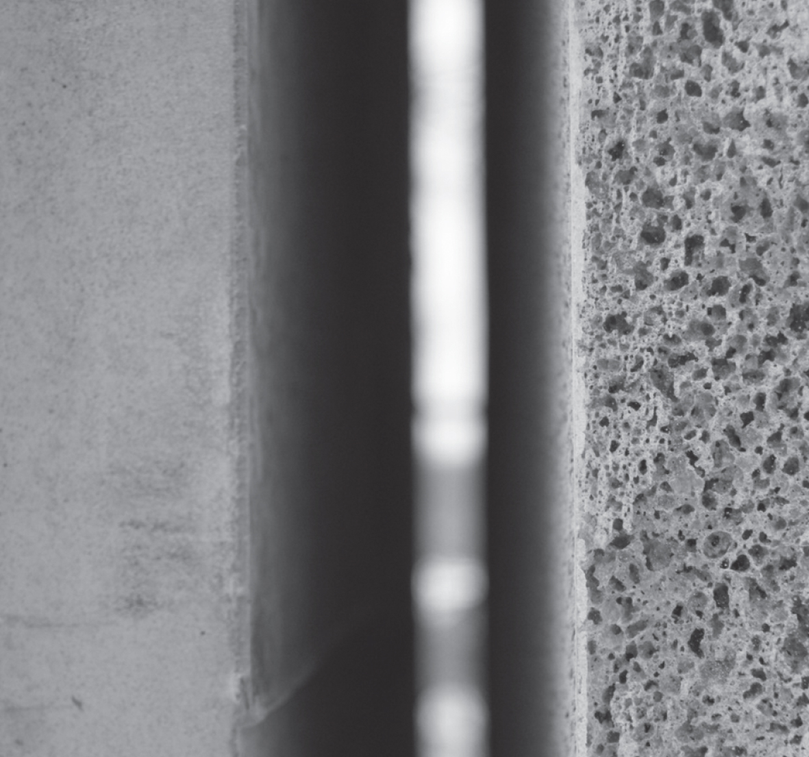
Fig.15
Four-point flexural strength test with a micro-reinforced, ultra-high-performance concrete.