Evaluation of free-form concrete architecture, moulding systems and their technical potentials
Abstract
This article deals with the analysis of applied radii in built architecture. This basic evaluation is part of a DFG (largest German research funding organization) research project ‘Basics to develop adaptive formwork systems for free-formed concrete building parts’. It serves to pre-configure adaptive formwork surfaces. The article describes the changes in modern architecture, from rectangular box to free-formed ‘blobs’ in terms of the geometry and the resulting issues of costs and manufacturing process.
1.Introduction
Since the Nineteen-Nineties, the building industry has been subjected to fundamental structural changes. Cost competition forces building companies – also those working in the field of reinforced concrete - to calculate to the very limit in order to acquire job opportunities (Girmscheid & Kersting, 2010). The cost for formwork for reinforced concrete constructions accounts for a significant share of the cost for the building shell. Studies show that 30% to 40% of the cost for the overall shell construction of a reinforced concrete building is spent on formwork (Müller, 1972; Rathfelder, 1992; Hoffmann, 1999; Reichle, 2002; Girmscheid, 2011).
When looking at the development of reinforced concrete construction it becomes apparent that a start-up phase existed after the end of the Second World War during which rationalisation measures were started. However, rationalisation was generally restricted to the topic ‘reinforcement and concrete’. These rationalisation measures were soon exhausted, and the focus shifted toward the formwork, a process previously almost entirely unstudied. First improvements and approaches were made in pre-planning, new working resources (prefab formwork elements) and possible fields of application (Kowalski, 2001).
All of these improvements of formwork systems since the Nineteen Fifties have indeed simplified the process and contributed to time and therefore labour cost savings; however, these savings are often accompanied by system inherent limited flexibility in terms of adaptability to specific building geometries. But the geometries and complexity of modern buildings show that architectural requirements and desires for divers geometries continue to grow resulting from the possibilities that digital planning and design offers. Today, formwork for a large-area straight wall does not pose fundamental challenges anymore; however using the same formwork system for a skew footprint such as the designs by architects Zaha Hadid, Frank O. Gery or CoopHimmelblau require, it quickly becomes clear that these systems can only be applied with significant adaptation, resulting in high planning effort and higher formwork cost.
If following the demand of modern architecture – that is to say not to think about planar geometries but rather free-formed building volumes – the cost for formwork increases exponentially (see Fig. 1). Studies in the field of free-form moulding for concrete constructions related to the type of applicable formwork and thus a reduction in production and building cost are still very limited – rather, planning and execution of such buildings are realised with high expenditure and case-to-case construction development.
2.The development of formwork construction
Basically, there are no verified categorisations of the different currently available and applied formwork systems. The current European norm for formwork is DIN EN12812 (2008) Falsework – Performance requirements and general design “formulates requirements for tendering and use of falsework and contains methods for dimensioning (planning) of structural framework” (Hoffmann, Motzko, & Corsten, 2012).
Manufacturers differentiate their products by formwork systems for particular building tasks: wall formwork, ceiling formwork, support/column formwork, falsework, bridge and tunnel formwork and jacking formwork with the according subcategories. In principle, a wall system can be composed the same way as a ceiling system; thus specialist literature rather categorises formwork systems in system and specialised formwork.
• Fixed formwork (e.g. wall, ceiling, circular, support formwork)
• Movable formwork (e.g. jacking, sliding, lifting, pull formwork)
• Specialised formwork (e.g. vacuum, pneumatic, wooden freeform formwork)
The introduction of formwork systems and the system inherent simpler erection of the formwork resulted in using ever fewer qualified personnel to save cost. When comparing assembly since the Nineteen Fifties and today however, it becomes apparent how restricted and rigid today’s ‘widely applicable formwork systems’ actually are. Using the example of a sloped wall illustrates that the formwork system used in earlier times, consisting of loose wooden boards, was much easier to construct in problematic areas such as curved corner areas than with today’s formwork modules (frame formwork). Decimeter increments and the use of corner frames help to successively approximate a geometry (successive approximation); however, there always remains a residual area (see Fig. 2). Such additional formwork work onsite – even for relatively simple constructions – is time-intensive and, in technically highly developed countries with according labour cost, results in higher overall cost. More complex planar wall elements exhibit even greater formwork requirements and thus increased cost. And if fair-faced concrete quality is the ultimate goal, the process is even more difficult due to the formwork joints. It should be noted that for the production of formwork with small radii or planes the most effort is expended on the formwork skin, whereas the load-bearing construction plays a minor role in terms of production efforts. However, this fact is reversed for large radii or planes. Here, the expenditure to produce the load-bearing element (support structure) is higher than that to produce the formwork.
In summarising the history of formwork, it can be said that no significant development has occurred except for the movable and unitised formwork systems. In spite of any developments the share of cost for labour related to the overall formwork cost for a concrete high-rise building is still at between 65% and 70% today, and thus constitutes a significant cost factor (Schmitt, 2001). This is mirrored by the concluding citation from Prof. Dr.-Ing. Friedrich H. Hoffmann: “Surely there have been positive changes in the field of formwork construction such as in other areas in the years after World War II; and this shall continue in the future. However, a fundamental change has not occurred aside from individual temporary fashions and large area formwork. Primarily, improvements in the shape of technically advanced and simpler single parts are recognisable.” (Hoffmann, 1993, p. 14).
But the described development of system formwork typically refers to planar, mostly orthogonally executed building projects. For non-linear building forms or for the use of bionically coined form finding methods, the realisation are to facilitate material efficient steel concrete load-bearing structures that pose a particular challenge for formwork technology. Hitherto common formwork systems have little flexibility and require significant expenditure of material and resources to create the desired form. They limit the possible form spectrum and contradict the goals of the form finding method as well as the desire for individual building contours. Currently, formwork systems for curved concrete building shapes exhibit a very rigid deformation behaviour with little ductility. If the surface curvature cannot be linearized or approximated segment by segment, two methods are commonly used.
Firstly, general planes are reduced into developable ruled surface, whose formwork is then mounted on a wooden console by means of a number of specially cut beams. Milling of negative forms (e.g. in foam blocks) can be used to create formwork for double-curved surfaces. The foam blocks are joined into a formwork segment with a customised support structure. Both variants are based on a rigid form for single use without the possibility of modification. One method of creating a suitable fair-faced concrete surface with higher requirements is to laminate the surfaces with, for example, epoxy resin. Pneumatic formwork systems play a special role. Pneumatic formwork typically means membrane structures held in shape with pressure that serve as formwork structure as well as formwork skin. The principle is analogue to that of a load-bearing air hall. Typically, such membranes are made of PVC coated polyester or polyamide textiles. The advantages of such constructions lie in the reusability of the formwork material and a quick assembly/disassembly of the formwork structure. The disadvantage lies in the spectrum of application; generally said it can only be used for synclastically shaped load-bearing structures (cupolas) (see Fig. 3).
2.1.Experimental development
In addition to the established formwork systems, various protagonists from research, education, engineering and the industry have been busy for years to identify simplified methods to create formwork for non-linear or free-formed building parts (see Fig. 4). These methods can be differentiated in experimental as well as non-building industry methods. One example for non-building industry methods is a deformation technique developed at RWTH Aachen, Institute for Structural Design and IBF (Institute of Metal Forming IBF, RWTH Aachen University, Germany) called ‘robot based incremental sheet metal deformation’. Sheet metal is brought into the desired shape with the help of two robotic arms. One robot deforms the sheet metal from above with a very small semi-sphere tool, and the other provides the necessary counter pressure from below. Due to the fact that the piece of sheet metal is clamped tightly, its original outer shape remains the same and the new shape is pressed or stretched out of the thickness of the metal. This method is not yet used for formwork in the building industry; but could offer potential for formwork with a high degree of repetitive parts (Trautz, Heyden, Herkrath, Pofahl, Hirt, Taleb-Araghi, & Bailly, 2012).
Methods on an experimental basis or in a development state can be generally differentiated into three categories – predominantly material based, CAM manufacturing methods or a combination thereof. Examples of predominantly material-based formwork systems are textile/membrane materials to create formwork (fabric formwork) for free-formed concrete building parts. A tensile-loaded material which, after inserting and curing the concrete, becomes a compression-loaded building part that can optimally absorb and dissipate forces, bears very high potential. Potential is to be expected in terms of material efficient use for the formwork as well as the concrete building part.
One example of CAM manufacturing methods is the adjustable mould; a method that uses a flexible surface as formwork skin in a height adjustable formwork table. It was developed and a first prototype made at TU Delft (NL), chair of Prof. Dr.-Ing U. Knaack under guidance of Dr. Karel Vollers and Ir. Daan Rietbergen. In parallel, another prototype of a lying formwork table was developed by the Danish company ‘adapa’ in Aarlborg. The development is intended for the realisation of thin walled fibre concrete panels for facades. This system is one of the newer methods to produce double-curved elements. At first, extendible actuators are individually controlled by computer to shape the elastic formwork skin. Then fibre reinforced concrete is deposited into the formwork surface. After the concrete has cured, the completed concrete element can be simply detached from the mould, which in turn can be reshaped into its original shape. Large planes are divided into shapes fitting into the system. A current DFG research project at TU Darmstadt involves researching and developing form-active vertical wall formwork systems that allow to adjust almost vertical formwork surfaces by means of a grid of actuators to the geometrically defined shape (see Fig. 5). In this case, the actuators not only have to impress the desired shape, but must also take on a support function, which requires a fixed connection with the formwork skin – an essential aspect of the structural shaping and controlling process (Michel, 2014).
TU Braunschweig together with the ITE (Institute for Structural Design) and the IWF (Institute of Machine Tools and Production Technology) researches the combination of established CAM methods, milling and material research to create ‘no-waste wax formwork’ (see Fig. 6).
The goal of the project is to develop a new universally valid formwork technology to produce concrete building parts (particularly UHPC, but also everything between regular and lightweight concrete) in the most economic manner possible and in virtually any complex geometric shape with, for example, sharp edges, very small radii and undercuts with maximum precision (see Fig. 7). Furthermore, this new formwork technology is to be sustainable, striving for absolute avoidance of waste products. The forming material used is industrial wax which, by melding can be returned into the material cycle in its entirety (‘Closed Loop Recycling’). In order to cover a large variety of shapes and applications the project focuses on researching two basic areas of use: manufacturing of ‘exterior wax formwork’, where the concrete is filled into the formwork, and ‘cavity wax formwork’ which displaces part of the concrete in a containing shape and creates a cavity in the concrete part after melting and removing the wax.
To accomplish this, a cooperation of ITE and IWF conducts basic research into the physical/technical properties of different waxes as well as into the effects of the wax specifications on the cutting property. This is to be followed by production, analysis and evaluation of waxformwork and the concrete parts created herewith. The final description of the determined optimum material and method parameters as well as an ecologic and economic evaluation shall make it easier for future users to apply the ‘no-waste wax formwork technology’.
2.2.In-situ - / prefab elements
The possibilities offered by digital planning in combination with CAM methods offer potential to create complex formwork. Application with in-situ concrete is as conceivable as is applying the formwork for prefabricated parts. In general, the planning process should include an evaluation of which formwork method is best suited for a particular building part. Considering prefabricated parts, a higher planning effort should be considered in terms of transportation (weight, dimensions) as well as the necessary joints between the concrete elements (Mainka, Kloft, & Heinemann, 2014).
3.Analysis of the building geometry
In the following analyses, the shaping radii of 160 realised concrete buildings are studied which include at least one one-directional curvature. The study aims to identify a spectrum of radii, or a systematic that predominantly occurs in architectural design. This data shall serve as the basis for developing a formwork system that, due to its setup, can react flexibly to different building tasks.
The radii used in the analysis are based on existing footprints and sectional views. The deciding factor for the selection of the particular radii was their dominance related to the overall building. With parabolic arc curvatures, the radius at the apex was chosen. For vertical hyperboloid structures such as cooling towers, for example, those three radii were determined that are necessary to generate the shape. On principle, the smallest and largest radii were evaluated; limited to a maximum of four radii per building. The goal is to filter all of the radii to identify those that are of relevance for the particular building task such as roof, wall or facade.
Chronological context:
The construction of curved surfaces can be traced back to the Stone Age in the shape of cupola-like roofing (so-called false vaults); the arc was created by projecting other stones (see Fig. 8). The first real cupolas were built during the first century BC in Rome (see Fig. 9). Until the 18th century, stone, brick, wood and natural fibres were used almost exclusively to build cupolas and arcs (Heinle & Schlaich, 1996).
From the Nineteen Thirties onward, with the introduction of high-strength cement and the possibility of guniting the concrete (dry spray process) load-bearing formwork construction gained in importance. Exemplary for this is the Zeiss Planetarium in Jena (completed 1926). Even though initially considered too elaborate and hardly realisable, a co-production with the company Dyckerhoff & Widmann resulted in the Zeiss-Dywidag-System (ferroconcrete formwork roofs). This development marked the beginning of the formwork era. Other important constructors of load-bearing formwork constructions are Pier Luigi Nervi (from 1925), Felix Candela (from 1950), Heinz Isler (from 1950) and Ulrich Müther (from 1964), amongst others (Kind-Barkauskas, Polonyi, Kauhsen, & Brandt, 2001).
Since the Nineteen Nineties, CAD software is broadly applied in architectural offices. Architect Frank O. Gehry, who used the software CATIA to design and build the fish sculpture in the entrance area of the business complex Vila Olimpica, Barcelona as early as in 1992 is considered one of the early pioneers. For the first time, the software made it possible not only to represent a project in a describable manner, but also to offer precise preproduction and to share consistent plans to all of the parties participating in the execution. And data to measure and dimension structural construction can be generated from a 3D model. Thus, Gehry’s designs are the first realised buildings of a new computer-supported architecture (Lazo, 2005). This development in digital planning led to a new type of architecture – manifested in the process of the development from the rectangular ‘box’ to free-formed ‘blob’ (see Figs. 10 and 11).
4.Assessment
The following graphs map the radii of the analysed buildings. A total of 160 buildings from the categories commerce/industry, residential, culture/education and special buildings were analysed (see Fig. 12). With 77 buildings, those made for cultural and educational purposes pose the greatest share, followed by commerce/industry with 43 buildings, residential with 27 and special buildings with 13 buildings. Noticeable are the high numbers for cultural/educational buildings on one hand and commercial/industrial buildings on the other. Buildings for cultural or educational purposes must often fulfil representative tasks. This is the reason why more is invested for ‘blob architecture’ in this category. Commercial and industrial buildings generally do not need to fulfil such representative tasks. Further analysis showed that particularly with this building typology radii were used for space-forming elements, i.e. roof constructions (16%) or barrel vaults and load-bearing formwork structures (55%). The use of these load-bearing formwork structures makes it possible to create very large column-free spaces – predestined for large commercial usage.
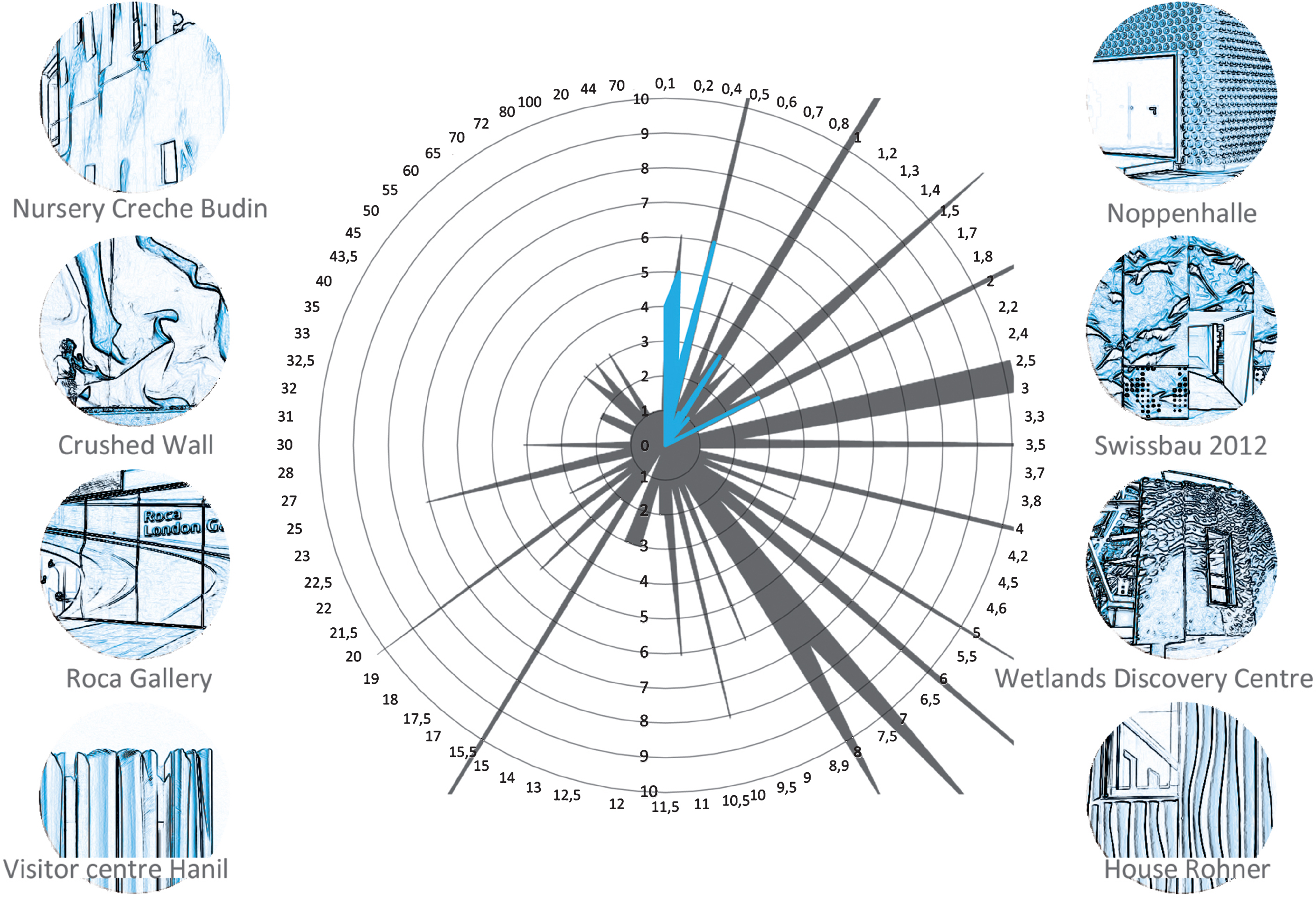
The following radius graphs depict the radii in meters on the outer scale, and the number of existing radii on the inner scale. The overall radius graph contains a total of 383 radii. The graph includes the single-curved radii (number of radii = 126) as well as the double-curved synclastic (A = 101) and anticlastic surfaces (A = 156). There are noticeable peaks with the radii 0.5 m to 1 m (A = 42), 2 m to 3 m (A = 36), 6 m to 8 m (A = 65) and 15 m (A = 22). When summarising these data, four groups of radii are important for further editing and analysis.
• <1 m,
• 2-3 m,
• 5–8 m
• 15 m
This shows the radii preferred for buildings. In further analysis they will have to be specified according to the particular building task. The following graphs subdivide the overall radii graph in order to optimise the results for individual requirements such as roof, wall or facade. These graphs are again subdivided into graphs for Gaussian curves, single-curved developable areas, double-curved non-developable synclastic areas and opposing double-curved non-developable anticlastic areas (see Fig. 13).
4.1.Analysis of the single-curved radii
The analysis of the total of 126 data records shows that these data also contains individual peaks. These radii lie in the ranges <1 m, 2.5 m, 4 m and 5–10 m. More detailed analysis of the radius spectrum of <1 m shows that they all refer to rounded corners; applied for directional changes in walls. The smaller the radius, the larger the angle. For a radius of approximately 20 cm (dependent on wall thickness) changes of the angle of 90° are possible (see Multimedia Pavillon, Jinhua).
Radii of >2 m are applied in wall elements. From a radius of 2 m onward it is possible to create a space with the minimum usable floor space.
4.2.Analysis of synclastic radii
With synclastic areas, 63% of the analysed radii are space-forming radii; mostly load-bearing formwork structures or cupolas. These convex, double-curved load-bearing structures are characterised by large spans with relatively slim formwork thickness.
For this type of building radii of <2.5 m can be neglected, since they are usually applied for building add-ons that have no load-bearing function, such as balconies. Only radii from >2.5 onward can be used to generate usable ‘spaces’. Radii between 2.5 m and 7 m are typically used in buildings with residential or cultural functions. Radii >7 m are generally found in commercially or industrially used buildings.
A large share of these buildings originated in the Nineteen Thirties as part of the boom of load-bearing formwork structures and was continued into the Nineteen Sixties. Important representatives include Pier Luigi Nervi (from 1925), Felix Candela (from 1950), Heinz Isler (from 1950) und Ulrich Müther (from 1964). From the Nineteen Eighties onward, load-bearing formwork structures were no longer mostly applied to commercial buildings but also for residential buildings and those with a representative character.
4.3.Analysis of anticlastic radii
The first buildings with an almost anticlastic area were built at the end of the 19th century in the form of towers (lattice water tower) with ruled surfaces. Even today it is seen as extremely elaborate to create opposing double-curved areas. Pure anticlastic buildings are currently found in the form of utilitarian buildings such as cooling towers, which are always based on ruled surfaces. Concrete buildings are rather rare due to the difficulty of creating the formwork. Usually, due to the complex formwork, anticlastic concrete shapes are restricted to necessary load-bearing structures in the form of stiffening staircases (Mummuth) as a design element or as roof areas (e.g. Rolex Learning Center). Precisely due to the complexity of production, the great majority of buildings or building parts with anticlastic radii have a representative purpose.
Here, a differentiation of the radii in anticlastic areas serves the evaluation – usually, however, one would call them free-form surfaces. The large spreading of the radii is due to many occurring changes in the direction of curvature, such as, for example, the facade panels of the project ‘Interior remodelling of the exhibition gallery of the bathroom furnishings company Roca’, London. These facade areas include radii of just a few centimetres as well as of metres. Looking at the roof-scape of the project ‘Rolex Learning Center’, Lausanne on the other hand, there are all applied radii in the range of >15 m. An analysis of the data solely considering the radii necessary to erect a building, for example the envelope of the project ‘Department Store Selfridges’, Birmingham or the ‘Graz Art Museum’ shows that only radii of >5 m are used. Most of these buildings are realised with successive approximation and then by optimising and separating in suitable areas with wooden boards, steel skeletons and glass infills.
5.Conclusion
The initial question of this study referred to the field of massive constructions and/or wall panels. The following assessments are thus restricted to this field.
The initially studied radii show that a large range of radii is used in buildings. The largest share (52%) of the studied radii is those of single-curved areas, followed by those of anticlastic areas (38%) and synclastic areas (10%).
When examining the radii of single-curved developable areas, it is noticeable that they are mostly used for massive constructions. In the field of facade panels, single-curved areas are only used with very small radii, for example applied in corner elements.
As described in the introduction, creating formwork with planar material for single-curved areas does not pose a problem. Therefore most curvatures are single-curved. System-optimised prefabricated formwork (round formwork) (R = >1 m) is available on the market for these types of applications.
Synclastic curvatures for vertical building elements are typically used in transitions from wall to roof area or slightly bellied buildings such as, for example, the post-and-beam facade of ‘P&C Weltstadthaus, Cologne’ by engineering firm Knippers Helbig, Stuttgart (architect Renzo Piano). Generally, the advantages of a synclastic area are used for load-bearing formwork structures. Here, the transition from wall, ceiling or entire building is gradual/flowing. However, when examining purely vertical building parts, radii of >6 m are of importance.
With anticlastic areas we need to differentiate between facades and massive walls. These mostly very complex shapes are often applied to representative buildings. Massive concrete buildings are rarer due to the necessity of elaborate formwork; examples are the Neue Zollhof (Düsseldorf, Germany, 1999), the MARTa (Herford, Germany, 2005) both designed by O. Gehry, and the Pavilion Blank (Colomiers, France, 1999) by Rudy Ricciotti Architects.
If after looking at the distribution of the radii used in modern architecture we examine the manufacturing methods, it is noticeable that, based on the initially described formwork methods according to the demand for free-formed concrete structures, pressure for development exists in the sense of freedom of form and cost effectiveness. Thus, in the case of the ‘Neuer Zollhof’ the project was realised with shape-milled polystyrene blocks for the formwork of the prefabricated concrete parts since another formwork technology did not yet exist (Lazo, 2005). Accordingly, it was not yet possible at the time to give the concrete walls a load-bearing function. In contrast, six years later the project ‘MARTa’ in Herford was realised as a massive structure with in-situ concrete because formwork technology had advanced (Peer, 1998). This technological development as well as the illustrated considerations of the individual radii used suggests the necessity to further develop free-form formwork systems in order to fulfil the demand for economical and technologically feasible formwork systems.
Upon completion of the analysis of the data the relevant radii to create building envelops (walls) proved to be >4 m. In general it can be said that formwork with small radii is more difficult to produce and is ‘stiffer’. Conversely, formwork with larger radii are easier to manufacture, but the formwork is ‘weaker’. Even though formwork with smaller radii is more difficult to produce and thus more cost intensive, its area of application is to complement standard surfaces (e.g. rounded corners) and, in combination with standard formwork, can be produced more cost efficiently than full-faced curved building parts with large radii.
These data form the basis for the partial project to develop adaptive formwork systems for free-formed concrete building parts of the focus program SPP 1542 ‘Light building with concrete’ in order to preconfigure an adaptive formwork surface.
Acknowledgments
The research presented was developed as part of a master thesis of the first author at the Detmolder Schule für Architektur und Innenarchitektur in the Faculty of Architecture in 2013. It is part of the literature study for the PhD research at TU Darmstadt. The authors would like to thank the Delfter Façade Research group for their support, especially the leader Dr.-Ing. Tillmann Klein.
The research was also part of the DFG project Leicht bauen mit Beton. The authors would like to thank the TU Dresden for support during the development of the research.
References
[1] | Girmscheid G. , & Kersting M. ((2010) ) Prozessbasierte Entscheidungsmodelle für die AuswahlprojektspeziSchalungssysteme Zürich, Switzerland: Eigenverlag des IBI an der ETH Zürich. |
[2] | Girmscheid G. ((2011) ). Rational schalen. Der Bauingenieur, 11: , 50–51. |
[3] | Heinle J. , & Schlaich J. ((1996) ) Kuppeln aller Zeiten – aller Kulturen Stuttgart, Germany: Deutsche Verlags-Anstalt |
[4] | Hoffmann F.H. ((1993) ) Schalungstechnik mit System: Bewährte Methoden, neue Entwicklungen Berlin, Germany: Bauverlag. |
[5] | Hoffmann F.H. ((1999) ) Schalungstechnik mit System. Berlin, Germany: Bauverlag. |
[6] | Hoffmann F. , Motzko C. , & Corsten B. ((2012) ). Aufwand und Kosten zeitgemäßer Schalverfahren. Third ed. Neu-Isenburg, Germany: Zeittechnik Verlag. |
[8] | Kind-Barkauskas F. , Polonyi S. , Kauhsen B. , & Brandt J. ((2001) ). Beton Atlas. Berlin, Germany: Birkhäuser Verlag. |
[9] | Kowalski R.-D. ((2001) ). Schaltechnik im Betonbau. Düsseldorf, Germany: Werner Verlag. |
[10] | Lazo C.E. ((2005) ). Frank Gehry. Minneapolis, MN: Lerner Pub Group. |
[11] | Mainka J. , Kloft H. , & Heinemann T. ((2014) ). A novel recyclable wax formwork-system for high-precision free-form UHPC members and joints, Proceedings of the IASS-SLTE 2014 Symposium, Shells, Membranes and Spatial Structures. Brazil. |
[12] | Michel M. ((2014) ). Grundlagen zur Entwicklung adaptiver Schalungssysteme für frei geformte Betonbauteile Publisher: TU Dresden. DFG / SP1542 – Leicht Bauen mit Beton, 120–131. |
[13] | Müller H. ((1972) ). Rationalisierung des Stahlbetonhochbaus durch neue Schalverfahren und deren Optimierung beim Entwurf. (Doctoral Dissertation), Universität Karlsruhe. |
[14] | Peer A. ((1998) ). Der neue Zollhof in Düsseldorf. Innovative Schalung für ein außergewöhnliches Bauprojekt. Beton, 48: (9), 538–544. |
[15] | Rathfelder M. ((1992) ). Moderne Schalungstechnik, Grundlagen – Systeme – Arbeitsweisen. München, Germany: Mi-Wirtschaftsbuch. |
[16] | Reichle E. ((2002) ). Einflussfaktoren für Aufwandswerte bei Schalarbeiten. TIEFBAU, 114: 624–626. |
[17] | Schmitt R. ((2001) ). Die Schalungstechnik: Systeme, Einsatz und Logistik. Berlin, Germany: Ernst & Sohn. |
[18] | Trautz M. , Heyden HW. , Herkrath R. , Pofahl T. , Hirt G. , Taleb-Araghi B. , & Bailly D. ((2012) ). Herstellung frei geformter, selbst tragender Faltstrukturen aus Stahlblech mit der inkrementellen Blechumformung (IBU). Stahlbau, 81: (12), 959–967. |
Figures and Tables
Fig.1
Example of a complex formwork – La Sagrada Família, Antoni Gaudí, Barcelona.
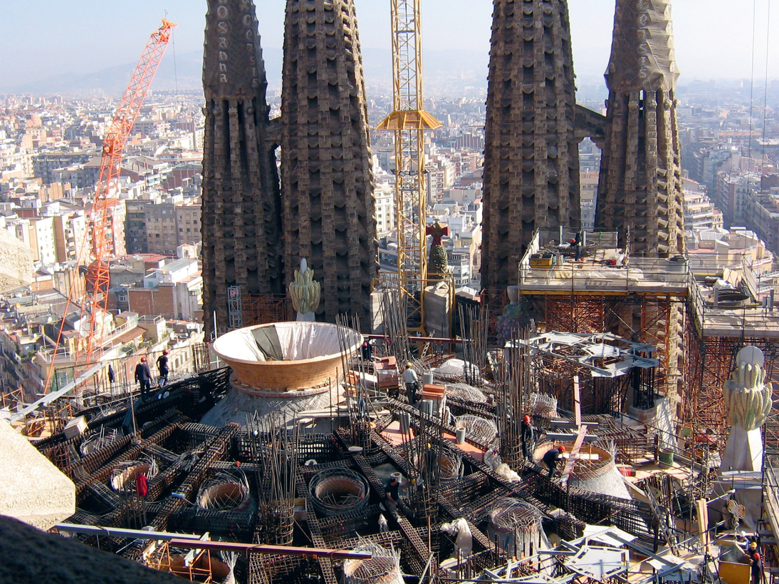
Fig.2
Example of formwork areas that require increased formwork efforts when applying formwork system modules.
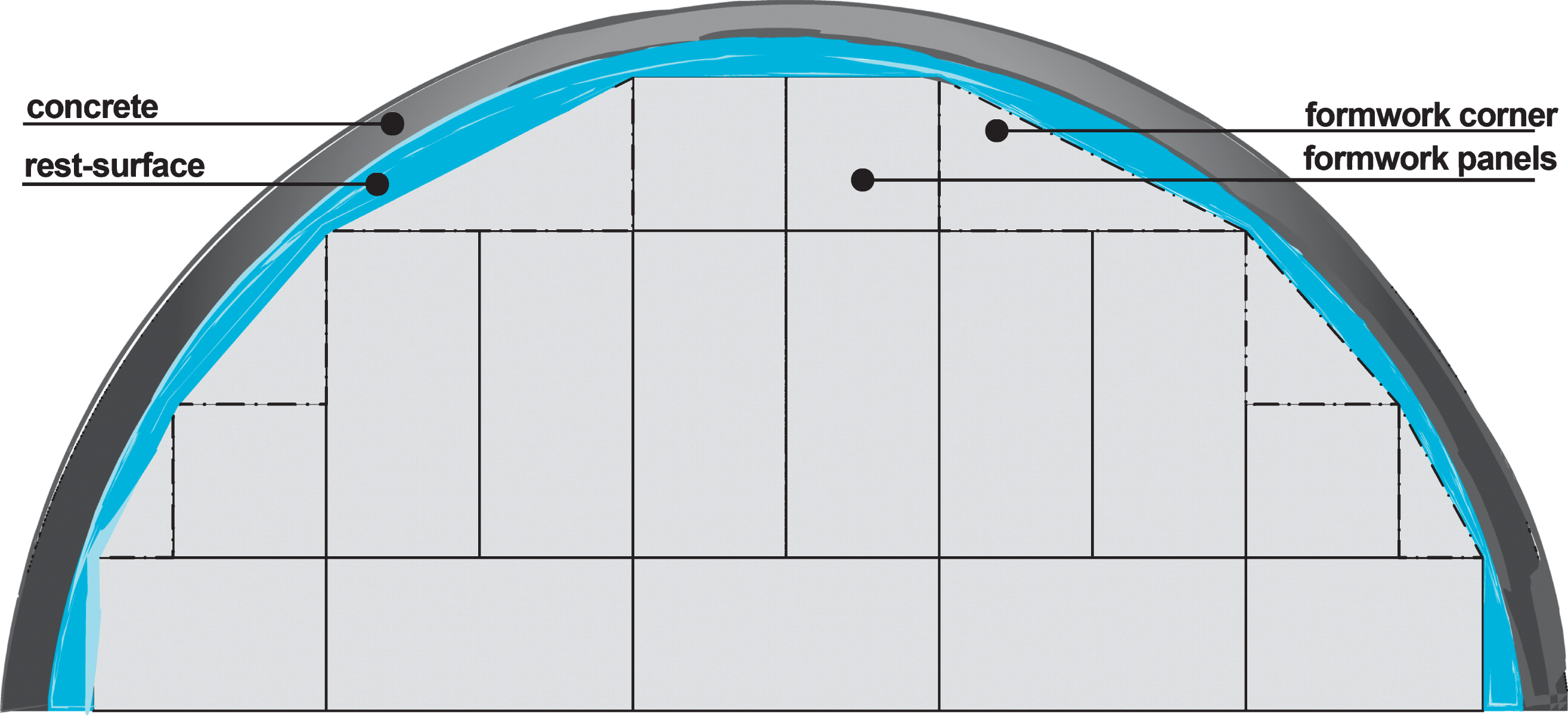
Fig.3
Conventional formwork – established formwork methods.
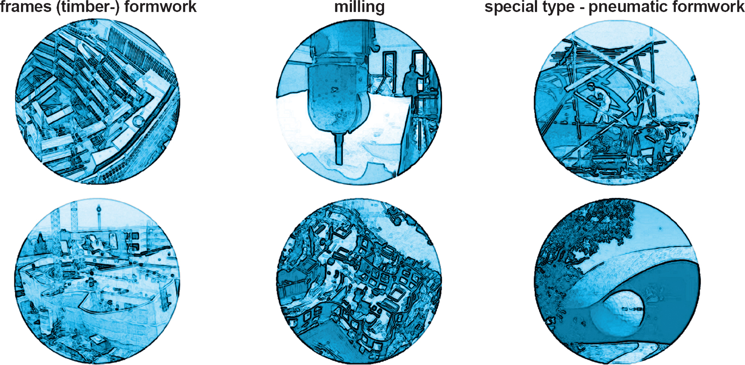
Fig.4
Example of incremental sheet forming (C) by David Bailey Institute of Metal Forming IBF, RWTH Aachen University, Germany.
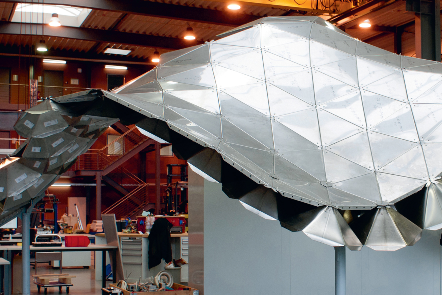
Fig.5
First prototype of an adjustable mould.
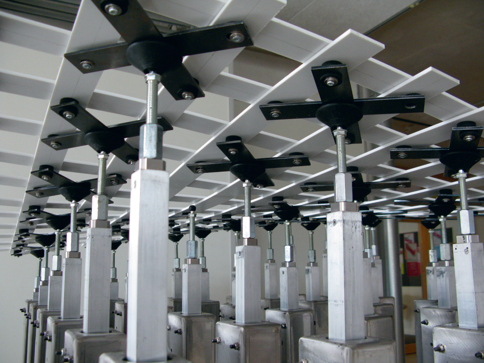
Fig.6
Processing of technical wax by milling. (C) Sarah Baron, IWF Institute of Machine Tools and Manufacturing, TU Braunschweig.
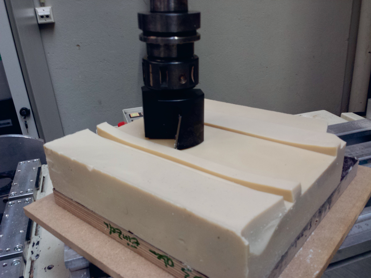
Fig.7
Principle of wax formwork technology - Wax moulds are filled with UHPFRC (C) by Jeldrik Mainka, Institute for Structural Design (ITE), TU Braunschweig.
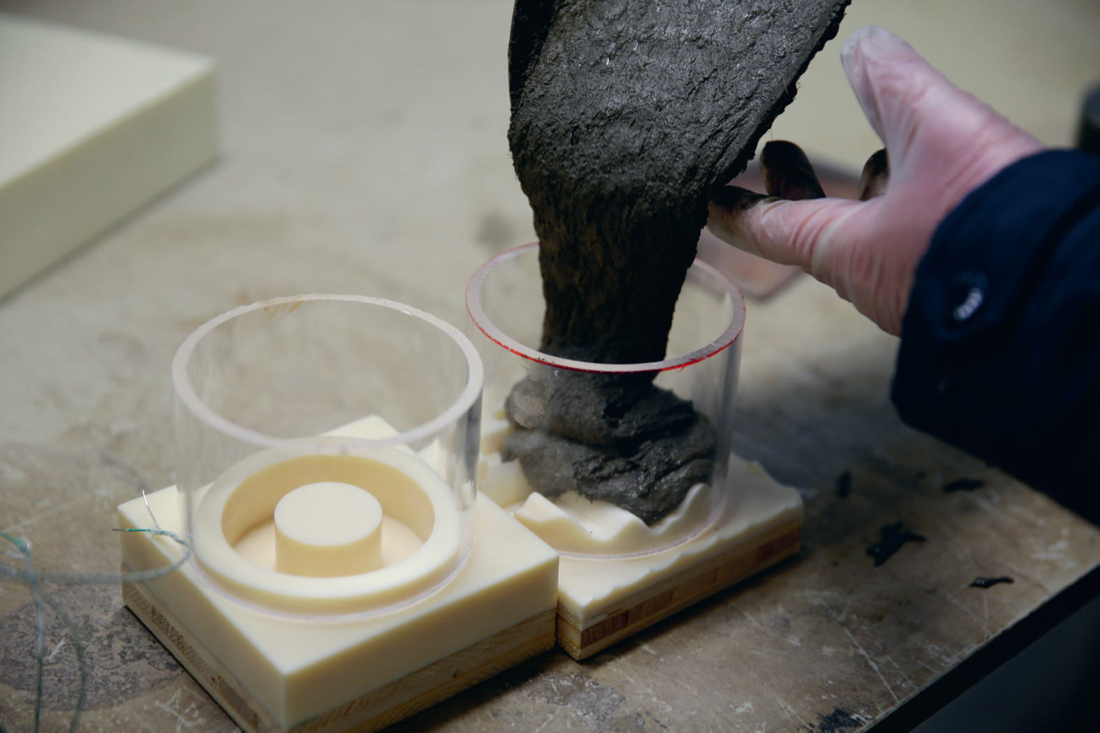
Fig.8
Schematic construction of a false vault.
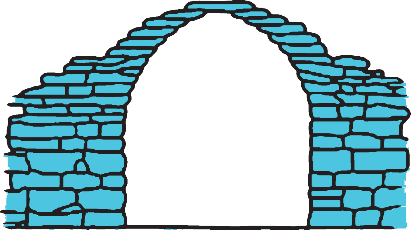
Fig.9
Pantheon Rome, View of the oculus. One of the first ‘concrete (opus caementitium)’ buildings.
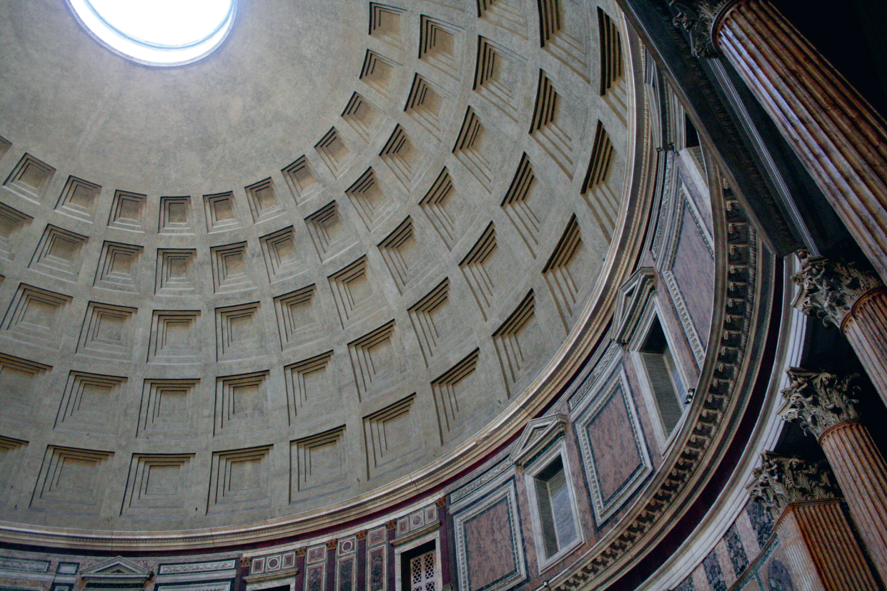
Fig.10
Iesu Church - Rafael Moneos ‘box-architecture’, San Sebastian.
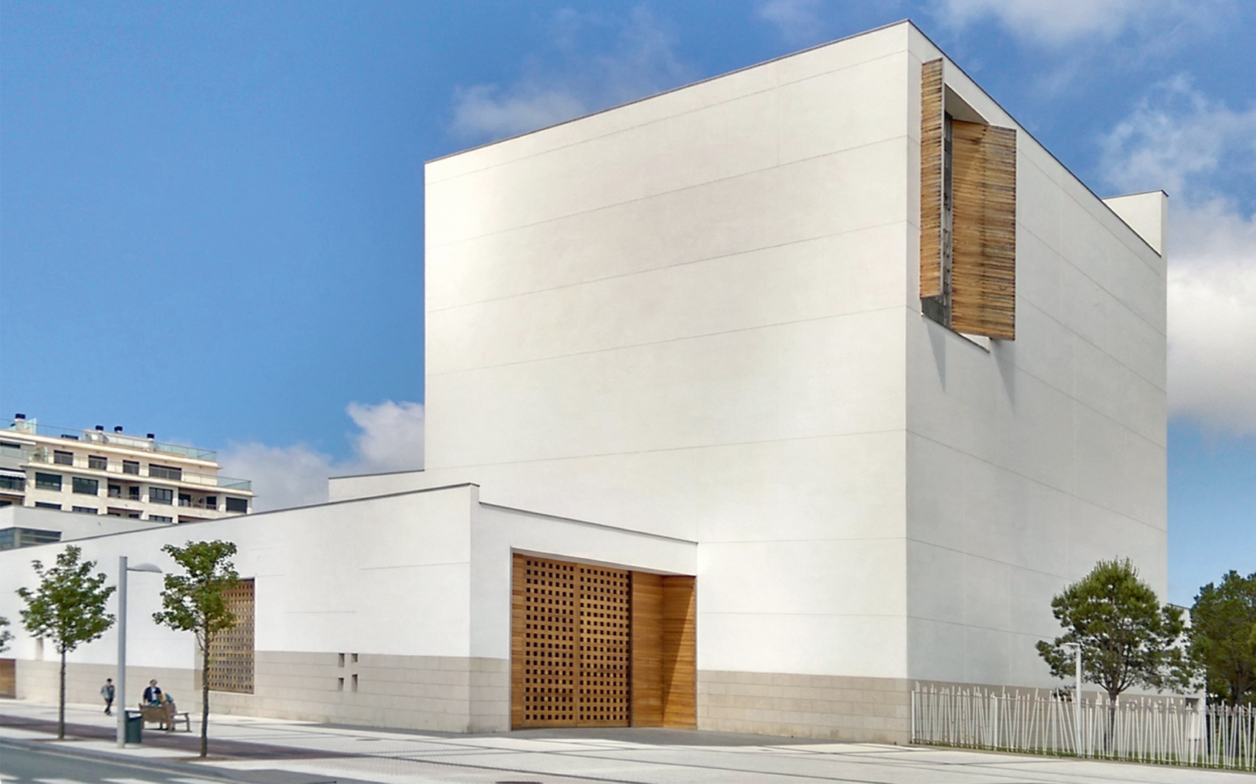
Fig.11
Guggenheim Museum - Frank O. Gehrys ‘blob-architecture’, Bilbao.
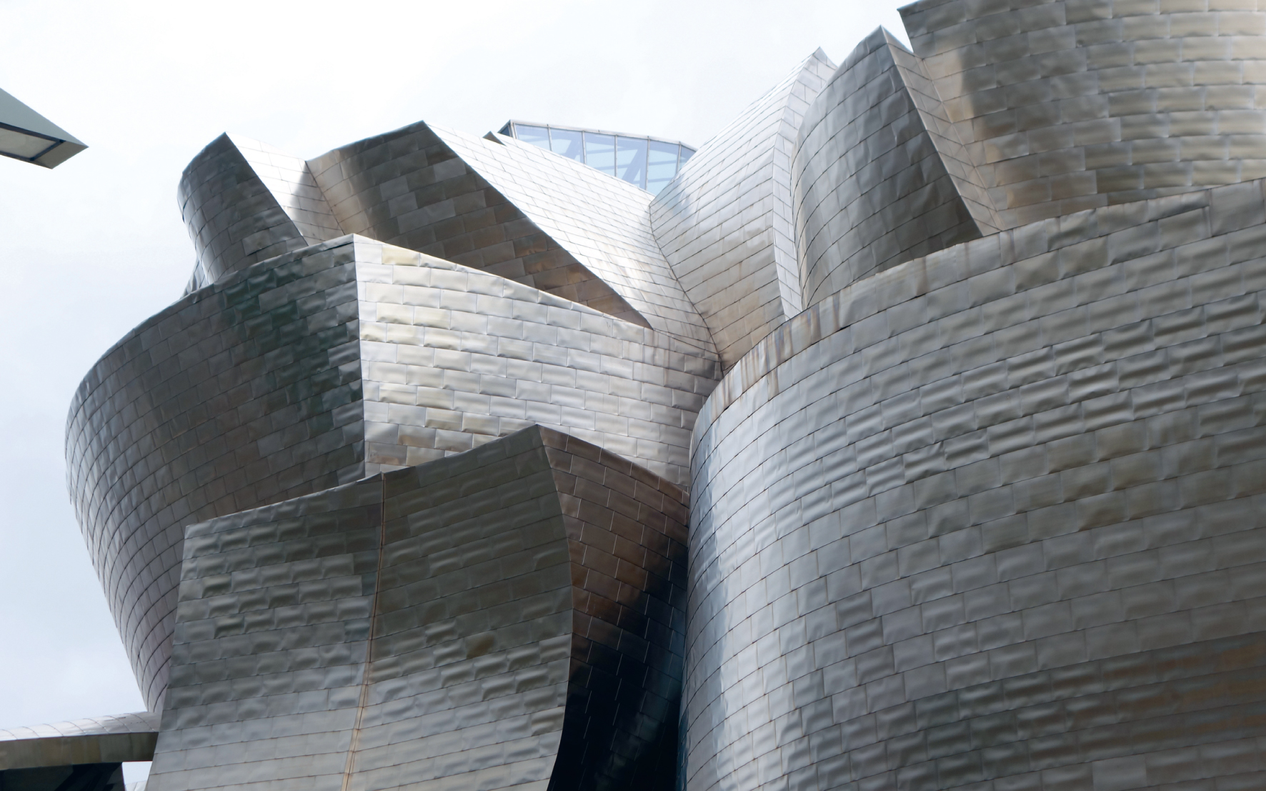
Fig.12
Analysed buildings sorted by the different surfaces and time.
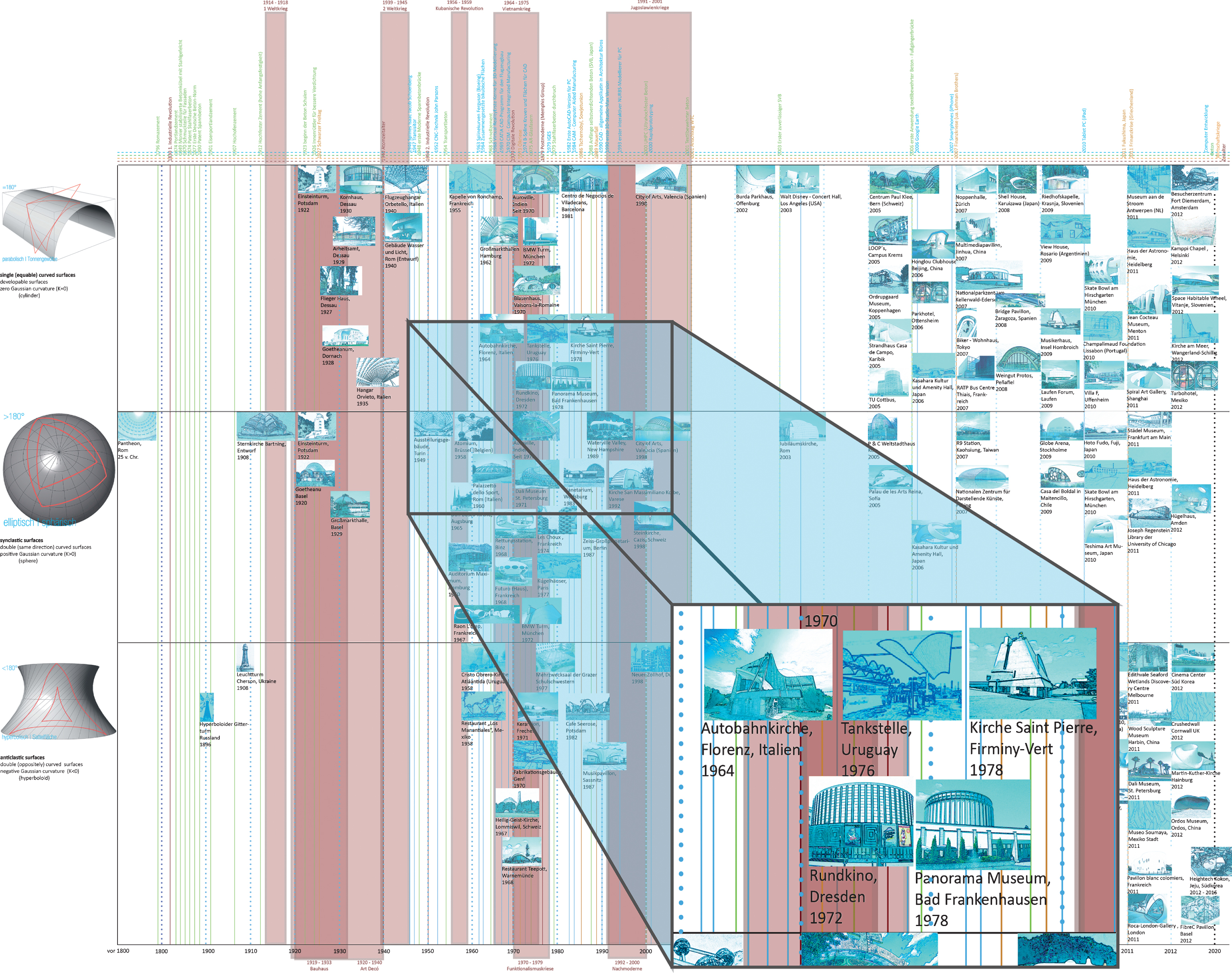
Fig.13
Radii chart ‘total’ includes all surfaces.
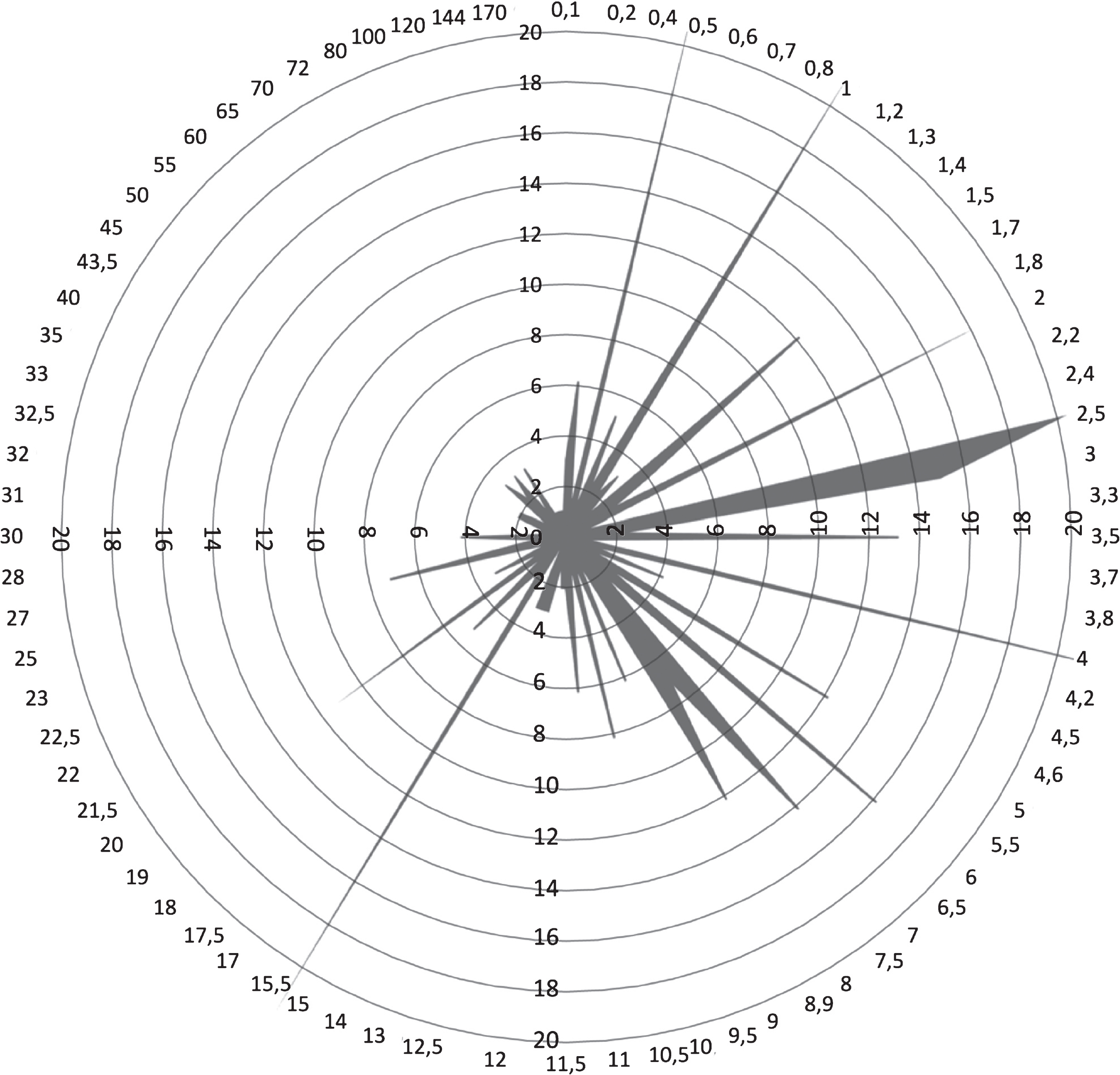
Fig.14
<1 m radii:
• Ordrupgaard Museum, Copenhagen, Facade planning PLH Arkitekter, Copenhagen, Architect Zaha Hadid, Culture/Education, 2005
• Multimedia Pavilion in Jinhua, China, Structural designer Hou Xinhua, Peking, Architect Knowspace, Special building, 2007
• Hongluo Clubhouse, Engineering office IDEA Design Studio, Florida, Architects MAD Office, Commerce/Industry, 2006.
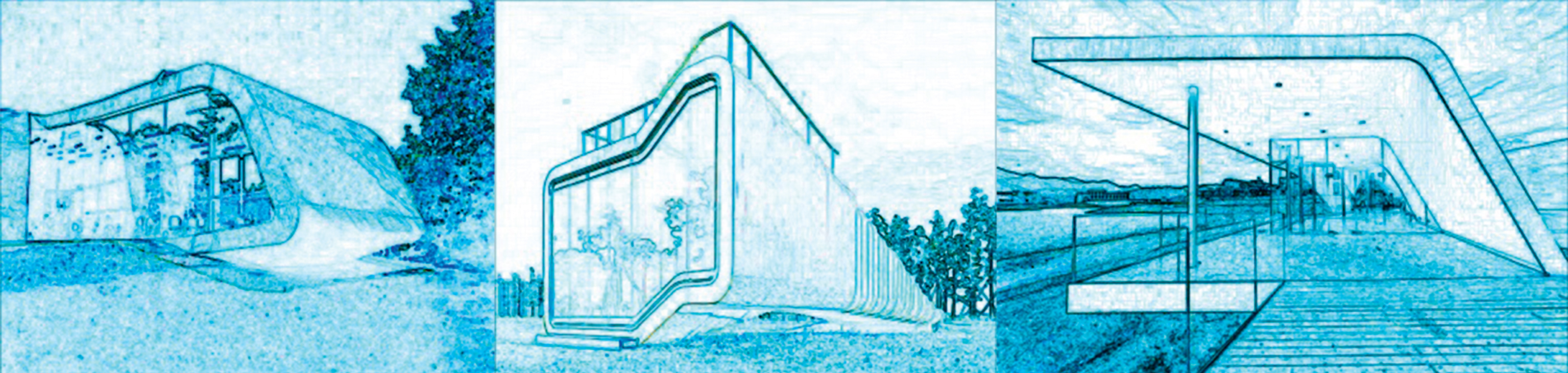
Fig.15
Radii >2 m:
• Visitor Center Fort Diemerdam, Amsterdam, Emma Architects, Culture/Education, 2012
• Biker Residence in Tokio, nakae architects, Residential, 2007
• BMW Four-Cylinder, Munich, Karl Schwanzer, Commerce/Industry, 1973.
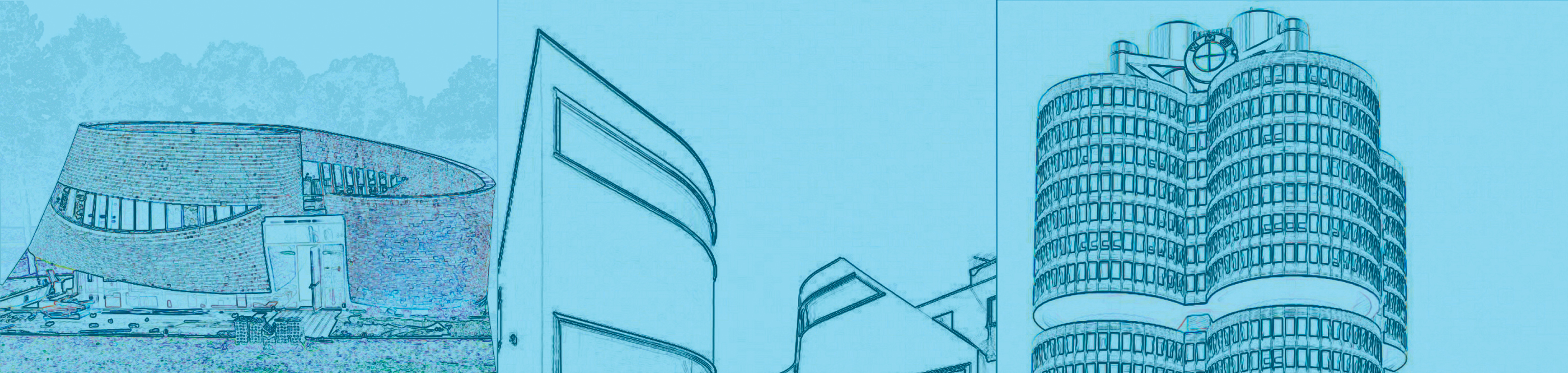
Fig.16
Radius graph with buildings exhibiting a single-curved area.
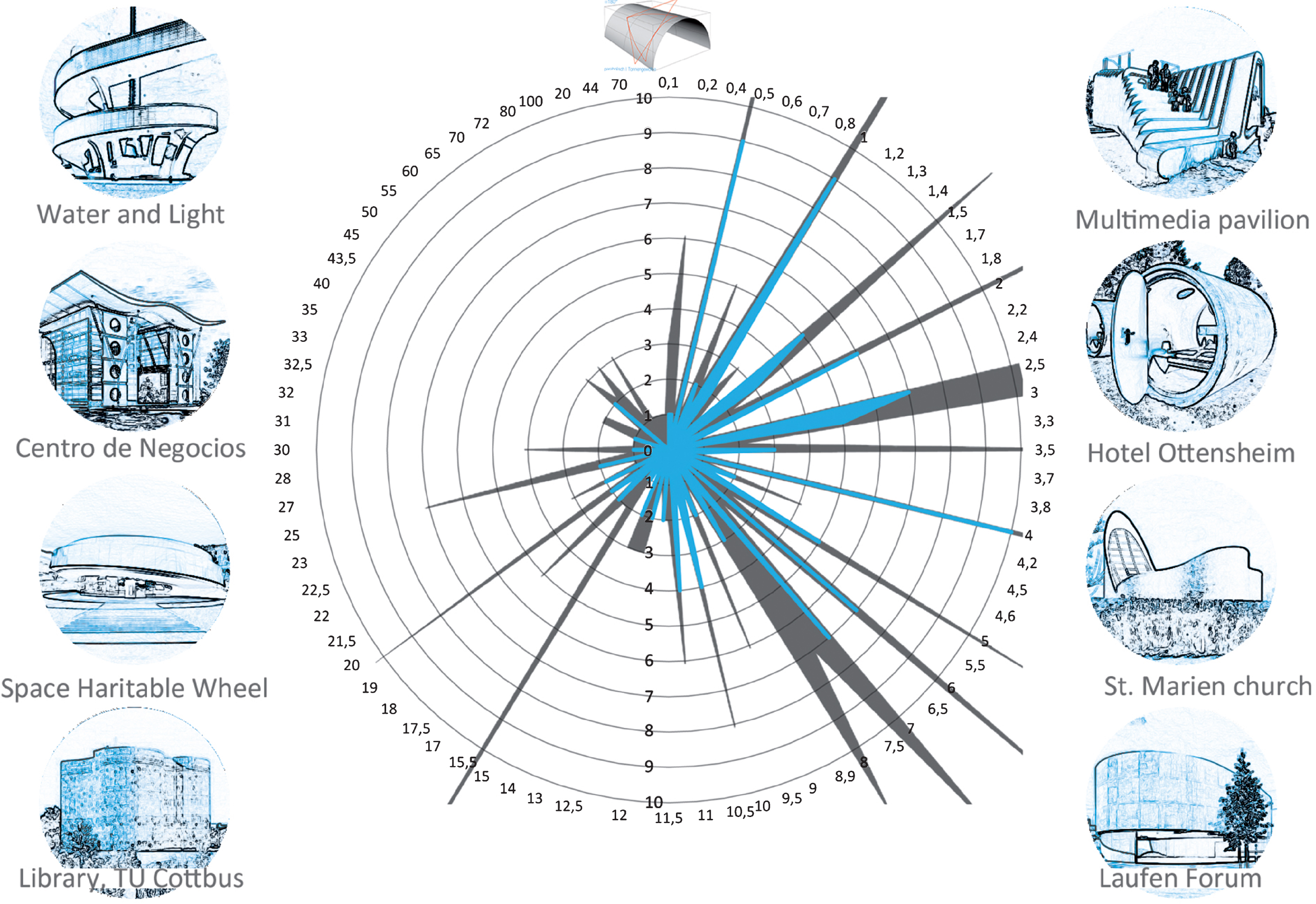
Fig.17
Radius graph with buildings that exhibit synclastically curved areas.
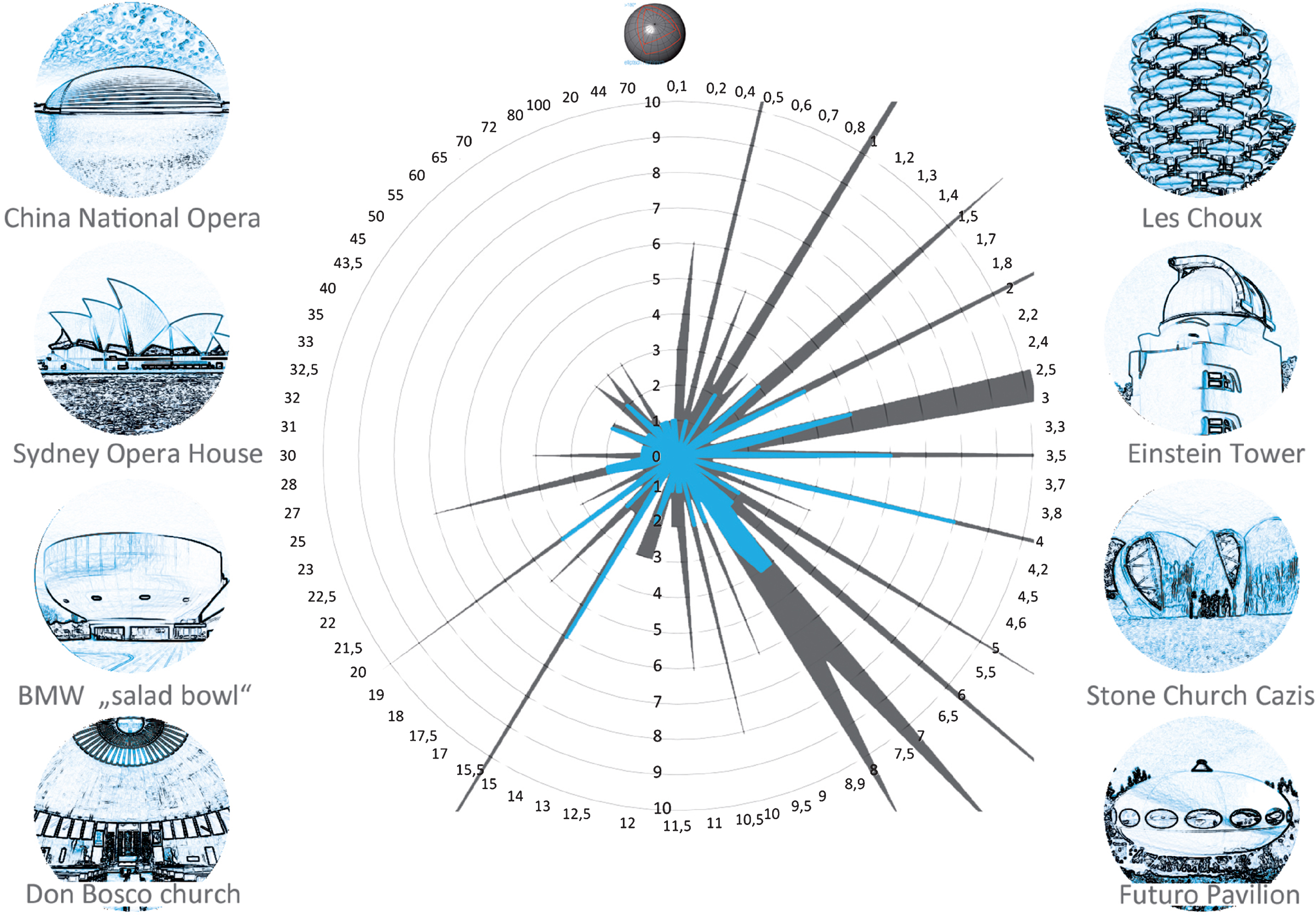
Fig.18
Radius graph with buildings that have an anticlastically curved area.
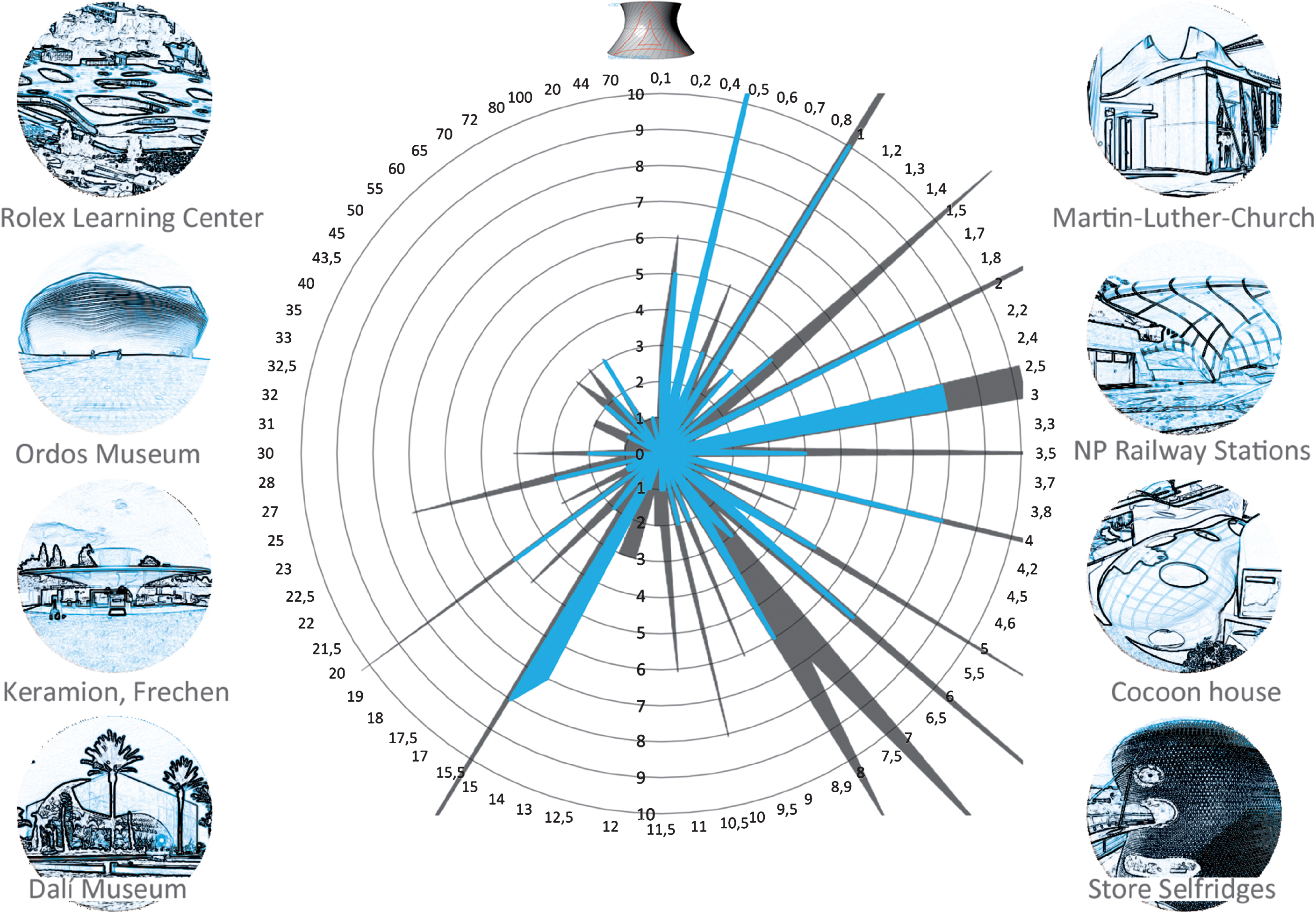
Fig.19
Radius graph with the relevant radii to create the outer envelop.