
Diagonally arranged louvers in integrated facade systems - effects on the interior lighting environment
Abstract
Building facades play an important role in creating the urban landscape and they can be used effectively to reduce energy usage and environmental impacts, while also incorporating structural seismic-resistant elements in the building perimeter zone. To address these opportunities, the authors propose an integrated facade concept which satisfies architectural facade and environmental design requirements. In Europe, remarkable facade engineering developments have taken place over the last two decades resulting in elegant facades and a reduction in environmental impact; however modifications are needed in Japan to take account of the different seismic and environmental situations. To satisfy these requirements, this paper proposes the use of a diagonally disposed louver system. Diagonally arranged louvers have the potential to provide both seismic resistance and environment adaptation. In many cases, louvers have been designed but not installed due to concerns relating to restricted external sight lines and low levels of natural lighting in the building interior. To overcome these problems, full-scale diagonally arranged louver mock-ups were created to evaluate illumination levels, the quality of the internal daylight environment and external appearance. Interior illumination levels resulting from a series of mock-up experiments were evaluated and correlated with results from a daylight analysis tool.
1Introduction
In recent years, it has become increasingly important not only to replace buildings, but also to renovate and improve the performance of the existing building stock. Especially in Japan, where building lifespans are generally short, increasing the duration of the building’s continued use can reduce materials required for new construction, waste from demolition and emission of CO2. In upgrading architectural stocks as social assets, it is necessary to improve building functionality whilst carrying out upgrades rather than continuing the existing trend towards ‘scrap and build’. Approaches that improve building functionality when upgrading will be more important in future from the perspectives of reducing environmental impact and the continuing use of existing buildings. Whilst being important elements that make up the urban landscape, facades provide a means to protect the building interior from its surrounding environment, and they have a direct impact on the interior environment. Hence, while changing the appearance of existing buildings, the appropriate reconstruction of facades in the refurbishment of existing buildings can be expected to offer improved building functionality including the reduction of environmental impacts. However, in Japan, many existing buildings do not satisfy the latest structural standards and they must be structurally retrofitted in order to reduce damage that would be caused by a large earthquake. In fact, many buildings which did not have enough seismic strength collapsed in Kobe and The Great East Japan Earthquake. In many seismic retrofitting cases, reinforcing elements such as steel braces are installed on the outside of the building as it is appropriate to focus on the building’s exterior skin when installing earthquake resistance elements. However, these reinforcing elements are often not designed in relation to the facade, resulting in poor aesthetic form and a situation contrary to the improvement of environmental functionality and better building stock. As the facade is an important part of a building in shaping the urban landscape and influencing the energy consumption of the building, it is essential to optimize the integrated design of the components used for anti-seismic reinforcement on thefacade.
2Purpose of the research
Based on these circumstances, the authors have proposed criteria for, and carried out analysis on, integrated facade systems that improve various characteristics (primarily appearance, safety and environment) when structural retrofitting is performed on existing buildings and structural elements are applied to actual buildings (Kanaki et al., 2008; Takeuchi et al., 2007, 2005, 2006a, b). Also, the safety performance of structural retrofit systems using Buckling Restrained Braces (BRBs) installed as diagonally arranged structural elements with minimum dimensions was confirmed in a previous paper (Kanaki et al., 2008). Figure 1 shows BRB configuration. BRBs have two main components. The first is a cross-shaped steel plate and the other is a steel mortar plank that serves to keep the core steel plate from buckling. BRBs are a structural element which manage both tension and compression forces. General brace elements used for structural retrofit are usually X or V shaped because they are designed only to take tension forces. A diagonally arranged bracing system is possible when BRBs are installed. Hence BRBs have the potential to integrate with facade elements as a diagonally arranged louver, camouflaging BRBs as a structural intervention. BRBs do not need to be installed in all the diagonal louver elements. One or two BRBs are deployed in one beam and one pillar span as required for structural performance. BRBs are designed to connect to box-shaped beams, and the allowable storey drift is (floor height/250) when pillars are designed for a shear fracture modes. Alternatively, allowable storey drift is (floor height/150) when pillars are designed for a bending fracture mode. As the reinforcing element, BRBs require minimal materials; just core steel plates and steel mortar planks; therefore, they can readily harmonize with facade components. For this reason, it is possible for BRBs to become an environmental feature such as an external louver etc. in addition to being a structural element.
This research supports BRBs as a multipurpose environmental device/structural element and proposes a diagonally arranged louver that integrates structural and environmental functionality. Also, the verification of interior illumination through measurements using a full-scale diagonally arranged louver mock-up was performed to determine the optimal design of diagonally arrangedlouvers.
3Background
Facade engineering which takes environment and energy efficiency into account, has progressed in recent years, especially in Europe (Kwok & Grondzik, 2007; Thomas et al., 2004). When applying such concepts to Japan where the climate is significantly different, modifications and improvements are necessary (Architectural Institute of Japan, 2002; Architectural Pictorial Special Edition, 2003; Architectural Institute of Japan, 2004). Additionally, the earthquake-proofing of existing buildings is an urgent issue in earthquake-prone Japan, and reinforcement through the deployment of braces on the outer surface of the building facade has become typical.
Figure 2 shows two types of typical structural retrofitting. Braces are naturally efficient as structural elements, though installing a structural element on the building’s outer surface does not necessarily improve its aesthetic appearance. On the other hand, there are many examples of the use of external louvers as an environmental installation in facades that both increase environmental functionality and improve visual appeal. Figure 3 shows examples of louver facades. The primary objective of louvers in reducing environmental impact is the improvement of sun shading. Figure 4 shows the shading mechanism of sustainable facades. By reflecting sunlight via the external louvers, heat penetration into the interior is reduced. Louvers installed on the outer surface of facades will outperform systems that exhaust heat via an intermediate buffer space (cavity) as in the recently proposed double skin facades, as they prevent heat penetration at the outside of the building (Michael, 2005; Oesterle & Lutz, 2001). The shape and pitch of louvers – horizontal or vertical angles – are adjusted during design for factors such as direction and solar altitude in order to obtain the required heat shading effect. In general, horizontal louvers are installed on southern elevations and vertical louvers are installed on eastern/western elevations in Japan (Architectural and Design Institute of Japan, 1963; Architectural Institute of Japan, 1963; Urano, & Nakamura, 1996). Figure 5 shows facade orientation and louver types effective in sunlight control.
Examples of diagonally arranged louvers proposed in this research are not shown here, however they create a heat shading effect in the south-eastern and south-western elevations for moderate solar altitude, and the heat shading effect can be expected throughout a significant period of the day. On the other hand, there are many concerns in the actual application of louvers due to problems of view obstruction and reduced interior illumination. Louvers are a type of system that excels in heat reduction through shading, however there are many cases where they are not used. Systems that introduce daylight into an interior such as daylight shelves are proposed for interior lighting. Figure 6 shows examples of daylight shelves. Although they serve to improve the interior lighting environment, these systems are only environmental devices. Cases where louvers are installed in an entire window for the purpose of heat reduction integrated with an interior lighting strategy have not been well studied (Architectural and Design Institute of Japan, 1975; Architectural and Design Institute of Japan, 1985). For this study, a diagonally arranged louver is proposed and the view from the inside and the interior lighting environment has been evaluated through full-scale mock-up experiment andanalysis.
4Methodology
Full-scale mock-ups of diagonally arranged louvers were created to evaluate illuminance levels and the quality of the internal daylight environment. Two types of diagonally arranged louvers (R type and C type) were set up with different shapes (rectangular and square) and louver pitches to evaluate daylight scattering by the louvers. External appearance of the full-scale mock-ups, and outside views from the interior were also checked to judge if louver facades are a possible solution for seismic and environmental retrofit. Full-scale mock-ups were painted with finishes to evaluate daylight scattering by the louvers and interior finishes. Direct daylight factor and daylight factor were measured by illuminometer and fish-eye lens. Indirect daylight factor calculated from the measured values was also used to evaluate daylight reflections by the louvers. Interior illuminance levels resulting from a series of full-scale mock-up experiments were evaluated and correlated with results from a daylight analysis tool. Analytical models were created based on experimental conditions such as louvers pitches, louver shapes and louver/interior finishes. The analysis tool ‘Radiance’ was used for the evaluation of interior illuminance levels and these values were compared with experimentvalues.
4.1Outline of full-scale experiment
Diagonally arranged louvers applied to Kanagawa University building No. 8 (north latitude 35.29, east longitude 139.37) were considered, assuming refurbishment of the existing building. Figure 7 shows applied diagonally arranged louver facades. Two different shapes of diagonally arranged louvers (R type and C type) were designed. In deciding louver dimension, the incorporation of a BRB (minimum cross section dimensions 100 mm×100 mm) was taken into account. R type has a rectangular cross section with the smaller side facing the outside. C type has a square cross section with a corner edge line facing the outside. Table 1 shows the appearance of the full-scale mock-ups of R type and C type for a single floor, single pillar span of the building. The authors considered the sun-shading effects of these two louver types and coordinated opening shading rate. Two types of louver pitches were arranged to maintain a similar shading ratio. The coverage ratio was 22.68 percent for R type and C type was 28.76 percent. BRBs are not deployed in all the louvers, and are only installed where structurally necessary. In this research, illumination measurements were performed using these two types of full-scale mock-ups.
4.2Overview of full-scale mock-up
Figure 8 shows the configuration of the full-scale mock-up. Primary brackets, secondary brackets and edge frames are used to join the louvers and braces to the main frame, which assumes use on an existing building. The louvers and the braces are attached to the edge frames by the primary brackets, with a cover plate attached to the joints. A white paint finish is applied to the mock-up, and the inner surface of the main frame has a matt black finish. In order to evaluate the daylight factor, the mock-up was installed, north-facing, on the rooftop of Kanagawa University Building No. 12, which has few obstructions to the sky. A north-facing mock-up is the best orientation to obtain reliable experimental values as the luminance distribution of the sky depends on weather and climate, and the former condition changes during the course of a day with the position of the sun. Figure 9 shows the installation environment and interior aspect of the mock-up. Figure 10 shows the full-scale mock-up elevations. The full-scale mock-up assumes a building interior perimeter zone, and has dimensions of: width 4400 mm×depth 5400 mm×height3450 mm.
4.3Experiment conditions
Table 2 shows the experimental conditions. In the experiment, the interior illuminance and unobstructed sky illuminance were measured (Architectural and Design Institute of Japan, 1977; Architectural Institute of Japan, 1993; Ogiso, & Koike, 1978). The unobstructed sky illuminance was measured simultaneously with the interior illuminance on the rooftop of Kanagawa University Building No. 23, adjacent to the mock-up installation location and the highest building in the University. Figure 11 shows the unobstructed sky illuminance and interior illuminance measurement environments. The illuminometer was placed in the centre of the pedestal of Fig. 11, shaded from direct sunlight for the illuminance measurements. Overcast skies are a similar condition to diffuse sky conditions; however, this condition was limited during the experiments. The authors considered direct radiation as the most relevant factor of external illuminance measurements because external daylight conditions are constantly changing. Therefore, in the physical model, the authors gave special consideration to avoid direct radiation by preparing an instrument for shading direct-sunlight to stabilize conditions. The external measurement method was the best solution to provide stable lighting conditions and one-hour interval measurements supplemented experiment data. The instrument for shading direct-sunlight is a 100 mm diameter iron disk, attached to a 10 mm diameter steel bar and covered with black tape like an umbrella. The disk and photo receiver are separated and supported so that a shadow falls upon the photo receiver. The instrument was not used in cloudy weather when a shadow cannot be cast.
4.4Measurement plan
Two daylight factor measurements were taken. One, the result of measuring illuminance by illuminometer, and the other calculated using a solid angle projection factor from photographs taken via a fisheye lens. Figure 12 shows the interior illuminance measurement points. The interior illuminance was measured for each condition at 1-hour intervals from 9 am to 3 pm over a 2-day period. Also, single measurements were made for each case to relating the solid angle projection factor of the measurement point to the window opening. The average value for the 2-day period was calculated using the hourly daylight factor derived from measured values. In the fish-eye lens photography, a Nikon Fisheye converter FC-E8 was installed on a Nikon COOLPIX4500 digital camera and photographs were recorded at the points where illuminance measurements were taken. The fisheye lens was adjusted to give a measurement height of 1025 mm, photographs were taken, and the solid angle projection factor (Sky Component) was found for the resulting image using SPCONV (Nagata, 2005). SPCONV is conversion software, which evolves Sky Component from digital photo data taken by a fisheye lens.
4.5Experiment results
Tables 3 and 4 show the results of illuminance measurements and the daylight factor calculated from them. Also, Fig. 13 shows three graphs plotting the daylight factor at each of the measurement points, with Table 5 giving the results of the experiment.
Daylight factor is the ratio of interior illuminance relative to skylight. When louvers are installed on existing buildings, it is generally assumed that the interior will become darker, due to shading by the louvers; however, on inspecting the measurement results it is evident that the interior brightness is not always reduced by louvers. Even if there are louvers, there are cases where the interior is bright and the lighting of the perimeter area is improved. At a location 4500 mm from the window, the results show an almost identical illumination level to that with no louvers. Also, where louvers are installed, the difference in daylight factor at 900 mm and 4500 mm from the window is small compared with the no louver case. The illuminance differences in the perimeter area are smaller when using louvers. Though illuminance differences are negligible, human comfort factors such as glare reduction are improved (Illumination Society, 1992; Illumination Society, 1994; Japan Industrial Standards, n.d.).
The direct daylight factor measured with the fisheye lens shows Sky Component obtained directly from the window opening. This is an index that is not influenced even if the measurement point brightness varies due to light scattering and diffusion from the surrounding environment. The relationship between the direct daylight factor and measured illuminance is shown in Fig. 13 as the indirect daylight factor. The indirect daylight factor is a ratio, which measures the influence of the interior walls and daylight scattered by louvers. The indirect daylight factor is larger when louvers are installed compared to no louvers at the point of 2700 mm and 4500 mm from the window. This is because the direct daylight is reduced and the far back of the room is brightened by daylight scattered and diffused by the louvers. Both the R type and C type have this tendency. The capture, scattering and diffusion of skylight by the louvers can also be seen from interior aspects of R type and C type in Fig. 9. Also, as the openings in the C type louver are wide, a free view is obtained of the outside scene (Illumination Society, 1987).
5Daylight analysis
5.1Analysis conditions
‘Radiance’ analysis software is used for interior daylight analysis. Radiance is an illumination analysis and visualization tool devised by the Lawrence Berkeley Laboratory in California. Table 6 shows the analysis conditions and Fig. 14 the analysis models. The analysis reflects full-scale mock-up experimental conditions. In Radiance, analytic daylight beams are traced randomly from the measurement points and analysis is carried out using the Monte Carlo method based on daylight rays that reach the source of daylight, the sun. Backward ray-tracing is an evaluation method in which a ray is tracked back from the eye position until it intersects with a surface. In basic ray-tracing, a ray is traced from the intersection point with a surface back to the source. If the surface is specular or transparent the ray follows the geometry of that reflection or transmission to the next surface before it is traced to the daylight sources. If the ray is not obscured by another surface or objects, the light reaching the intersection point from the sources is calculated. The ray-tracing process is repeated until the number of rays specified is reached. If a greater number of analytic daylight beams are configured, more accurate results can be obtained. In this research, analysis time can be reduced because the interior space is a rectangular shape, hence the number of daylight beams analyzed is set to a maximum value of 4096 rays. Also, the reflection number of analytic daylight beams is set a maximum number of 8 reflections (CIBSE, 1999).
5.2Comparison of analysis and experiment values
Figure 15 shows a comparison of daylight factors obtained from experiment and analysis. Although the analytical values show a lower illuminance level than the experimental values, a good correlation between the analysis and experiment can be seen in all cases. The difference between the computational simulation model and experiments was caused by varying measurement conditions in the experiments. Simulation results were stable but experimental conditions were not as stable as computer simulation models, because weather conditions were constantly changing. Additionally, in the experiments external measurement conditions were more unstable than internal conditions because the percentage of diffused light is greater if the measurement positions are in the back of the internal space. Diffused light, such as reflection from surrounding walls are stable. Because of the changing weather conditions, the daylight factor using external and the backspace illuminance was slightly different compared with computational results.
While not many diagonally arranged louver facades have been installed in existing buildings, it can be stated that reliable outcomes can be obtained at the design stage by performing analytical studies using the Radiance software. Figure 16 shows the interior illuminance distribution for no louvers and for diagonally arranged louver facades. When a diagonally arranged louver is deployed, a small bias in illuminance distribution can be seen over that with no louvers. However the illuminance distribution of C type louvers shows little bias in illuminance distribution – illuminance bias can be mitigated through the adjustment of louver shapes and attachment pitches.
6Conclusion
In order to understand the interior daylight environment of a facade with diagonally arranged louvers, a series of daylight illuminance experiments and analyses were carried out by means of a full-scale mock-up plus ‘Radiance’ daylighting simulation software. As a result, the following conclusions are drawn:
(1) Through the installation of a diagonally arranged louver, the interior illuminance variation in the vicinity of the window and interior of the room is mitigated. This reduces human discomfort caused by glare. Illuminance values are even and the daylight environment is improved in the perimeter zone when diagonally arranged louvers are installed.
(2) When a diagonally arranged louver is installed, daylight is scattered by the louvers and dispersed far back into the room, away from the window. Hence by installing a diagonally arranged louver, a brightness equivalent to the case where no louvers are installed can be obtained at the far back of the room.
(3) There is a bias in the interior illuminance distribution due to the diagonally arranged louver; however, this bias can be adequately mitigated through the adjustment of louver shapes and pitches.
(4) Reliable correlation can be obtained between the illuminance measured in full-scale mock-ups and analytical values. ‘Radiance’ provides a practical interior daylight design tool for diagonally arranged louvers.
Through this research, we conclude that the proposed diagonally arranged louver has the potential to improve lighting environments in the building perimeter zone. The performance is better than no-louvers and installation of diagonally arranged louvers for new and existing buildings is an effective solution for building upgrades. This solution can be applied in locations similar to Japan where building lifespans are short and is also less wasteful than scrap and build. Moreover, vertical and horizontal louvers do not have the same seismic resistance potential as diagonally arranged louvers. The proposed diagonally arranged louvers are multi-functional in environmental, seismic and aesthetic functions. They can play an important role in a future society concerned with sustainability.
Acknowledgments
This research was carried out using a Japanese Ministry of Land, Infrastructure, Transport and Tourism Grant Aid for Leading Technological Development for Housing and Construction; subsidy title: ‘Development of Regeneration Technologies for Existing Stock by means of an “Integrated Façade” that Simultaneously Attempts Performance Improvement in Design, Structure and the Environment’. We would like to express our thanks to Maeda Chikanori of Maeda First Certified Architectural Office for the guidance received in the design and manufacture of the mock-ups for this research. Hirai Reiko of Arup cooperated in the daylight simulation and Tadaki Hiroyuki, (then) graduate student of Kanagawa University assisted in the manufacture of the mock-ups and the execution of the experiments. We would like to express our thanks for their help.
Reference
1 | Kwok AG, Grondzik WT(2007) The Greenstudio Handbook, environmental strategies for schematic designEnquiry: A Journal for Architectural Research4: 2 |
2 | Architectural and Design Institute of Japan(1963) Lighting Design 16Shokokusha |
3 | Architectural and Design Institute of Japan(1975) Pamphlet 23, Illumination DesignShokokusha |
4 | Architectural and Design Institute of Japan(1977) Pamphlet 24, Measurement and Study of SunlightShokokusha |
5 | Architectural and Design Institute of Japan(1985) Pamphlet 30, Daylight Illumination PlanningShokokusha |
6 | Architectural Institute of Japan(1963) Lighting DesignGihodo Shuppan |
7 | Architectural Institute of Japan. (1993). Calculation Methods for Daylight Illumination. |
8 | Architectural Institute of Japan. (2002). Recommendations for environmental building. |
9 | Architectural Institute of Japan(2004) Architecture of GlassGakugei Shuppansha |
10 | Architectural Pictorial Special Edition. (2003). Façade Engineering, 39. |
11 | CIBSE. (1999). Lighting Guide LG10. Daylighting and window design. |
12 | Illumination Society(1987) Lighting handbookOhmsha |
13 | Illumination Society. (1992). Technical Standards Office Illumination Standards JIEC-001. |
14 | Illumination Society. (1994). Technical Standards Residential Illumination Standards JIEC-005. |
15 | Japan Industrial Standards (n. d.). Illumination Standards, JIS Z 9110-1979. |
16 | Kanaki Y, Takeuchi T, Miyazaki K, Iwata M(2008) Studies on integrated façade engineering. Structural performance of integrated façadesJournal of technology and design27: 137142 |
17 | Kanaki Y, Hikone S, Yamashita T, Iwata M(2008) Seismic strengthening by the buckling restrained bracesJournal of Architecture and Building Science634: 22152222 |
18 | Michael JC(2005) Curtain wallsBirkhäuser |
19 | Nagata A(2005) Building simulation resources Library. Application and DatabaseSPCONV |
20 | Oesterle L, Lutz H(2001) Double-Skin FaçMunich, GermanyPrestel |
21 | Ogiso, S., Koike, T. (1978). Concerning all Factors with Influence on the Actual Measurement of Daylight. Collection of Lecture Outlines from the Architectural Institute of Japan Mass Meeting. |
22 | Takeuchi T, Iwata M, Yasuda K(2007) Concrete engineering 500th commemorative editionThe Environment and Concrete145: 5 |
23 | Takeuchi T, Koyano K, Iwata M(2005) Studies on integrated façade engineering. Analyses on existing façadesJournal of Environmental Engineering592: 97104 |
24 | Takeuchi T, Koyano K, Yasuda k, Yuasa k, Iwata M(2006) aStudies on integrated façade engineering. Proposal for integrated façade and its evaluationJournal of Environmental Engineering601: 8188 |
25 | Takeuchi T, Yasuda k, Yuasa k, Okayama S, Miyazaki K, Iwata M(2006) bSeismic retrofit of aged building with integrated façadeJournal of Architecture and Building Science24: 161166 |
26 | Thomas H, Roland K, Werner L(2004) Façade Construction ManualBirkhäuser |
27 | Urano Y, Nakamura Y(1996) Architectural and Environmental EngineeringMorikita Publishing Co., Ltd. |
Figures and Tables
Fig.1
Configuration of bucking restrained brace.
Fig.2
Appearance of general seismic retrofits.
Fig.3
Facades with consideration for environment impact. Left: Lloyds Resister of Shipping, London, UK, Richard Rogers Partnership, 2000. Center: Telefonica, Madrid, Spain, Rafael de La Hoz Architect, 2005. Right: Ropemaker Place, London, UK, Arup Associates, 2008.
Fig.4
Shading mechanism of sustainable facades.
Fig.5
Facade orientation and louver types effective in sunlight control.

Fig.6
Examples of environmental devices (daylight shelf).
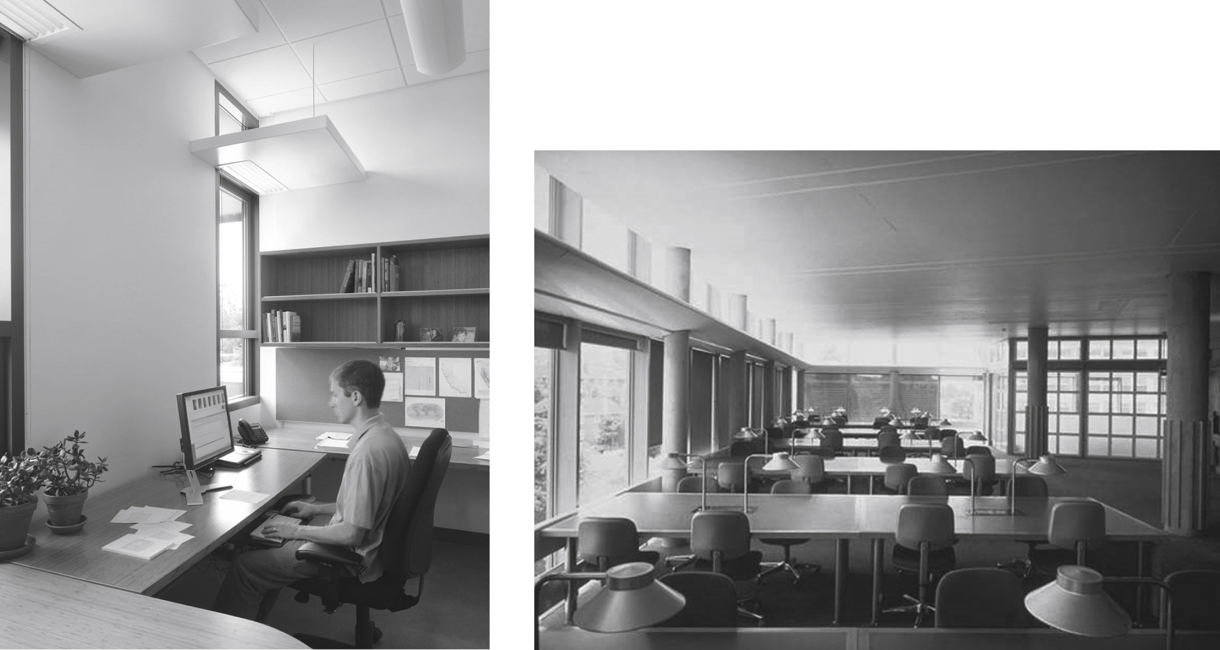
Fig.7
Facade with diagonally arranged louvers.

Fig.8
Configuration of the full-scale mock-up.
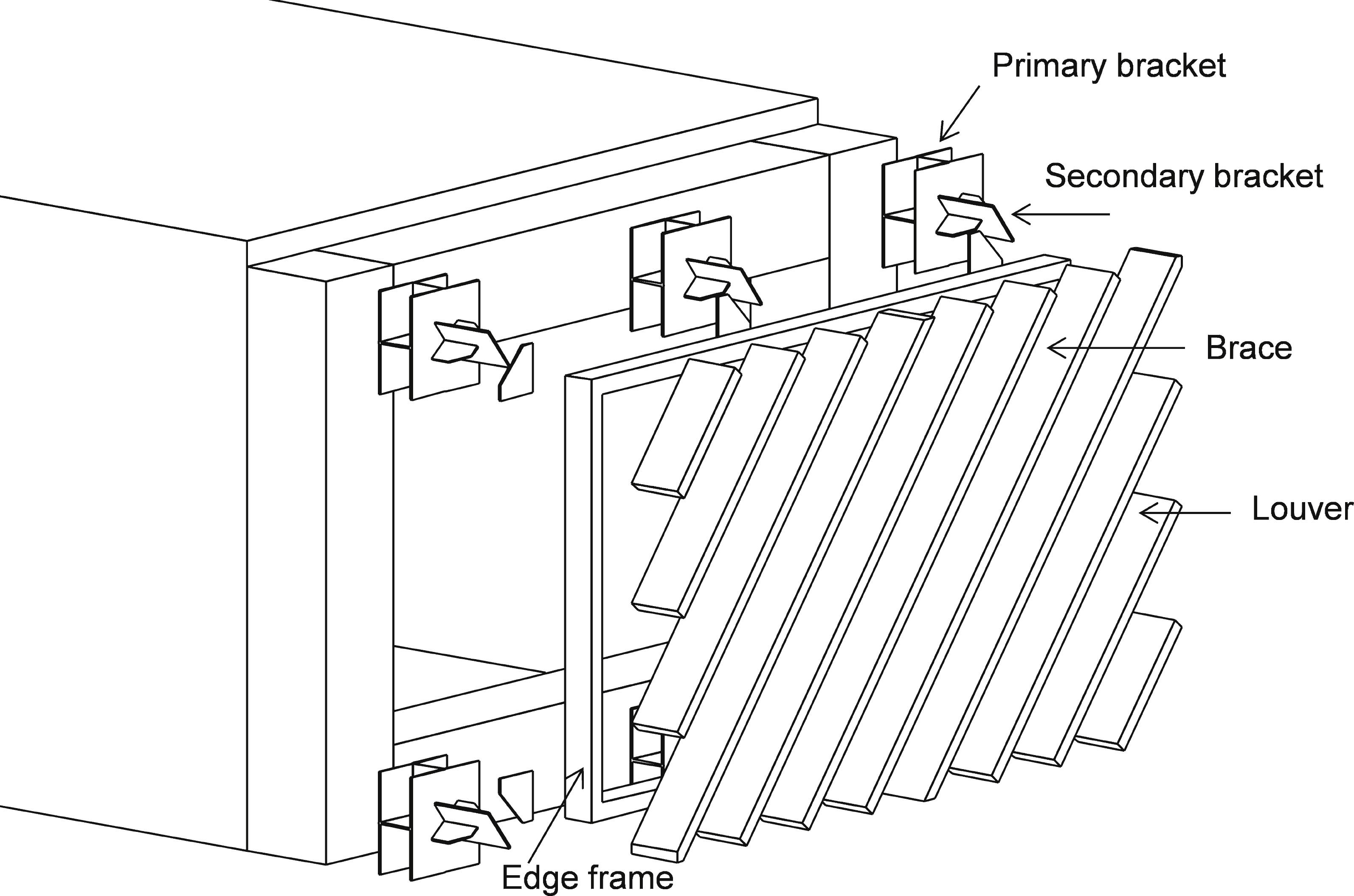
Fig.9
Surrounding environment and mock-up (view from interior side to outside).
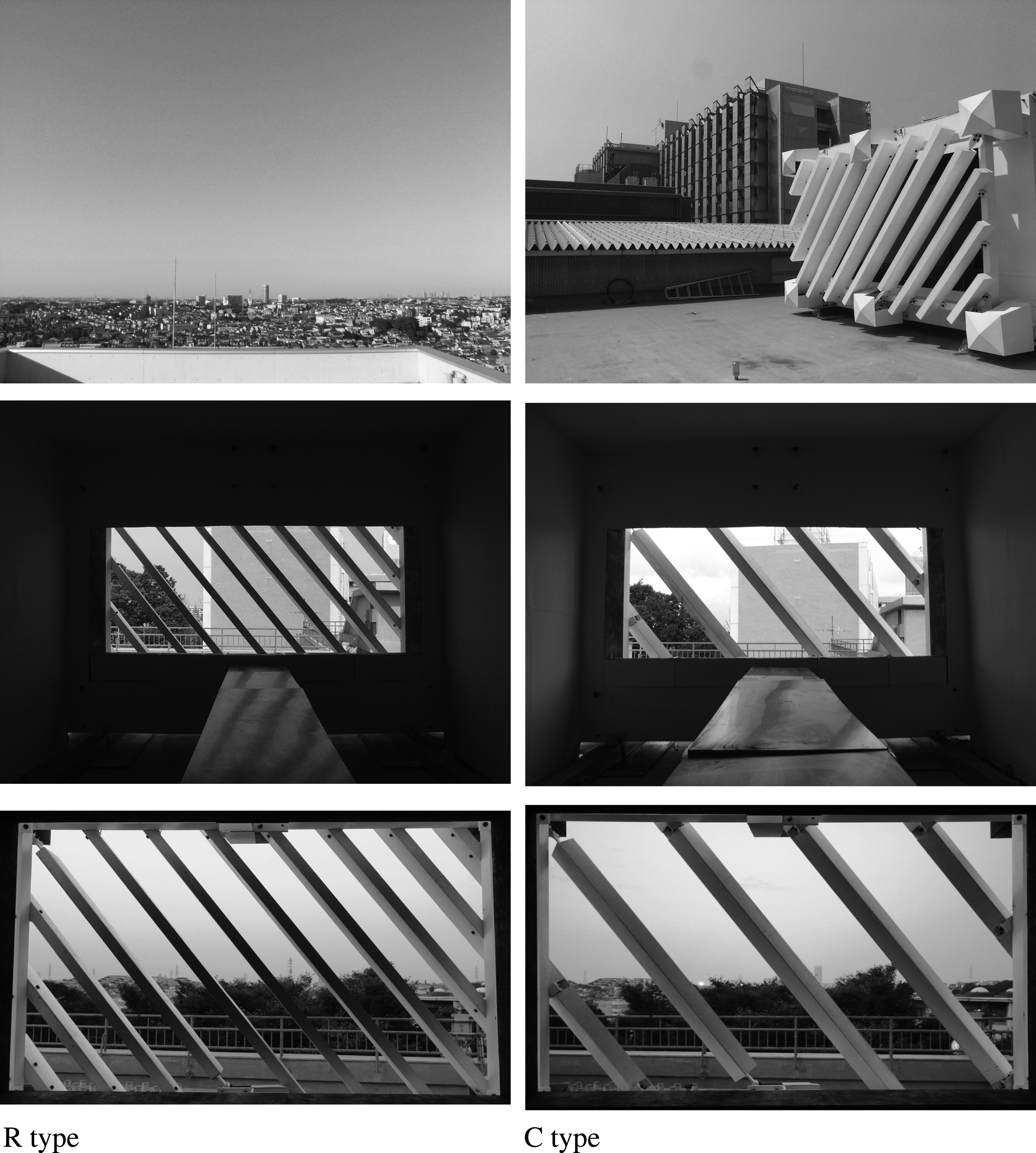
Fig.10
Mock-up elevations (unit; mm).
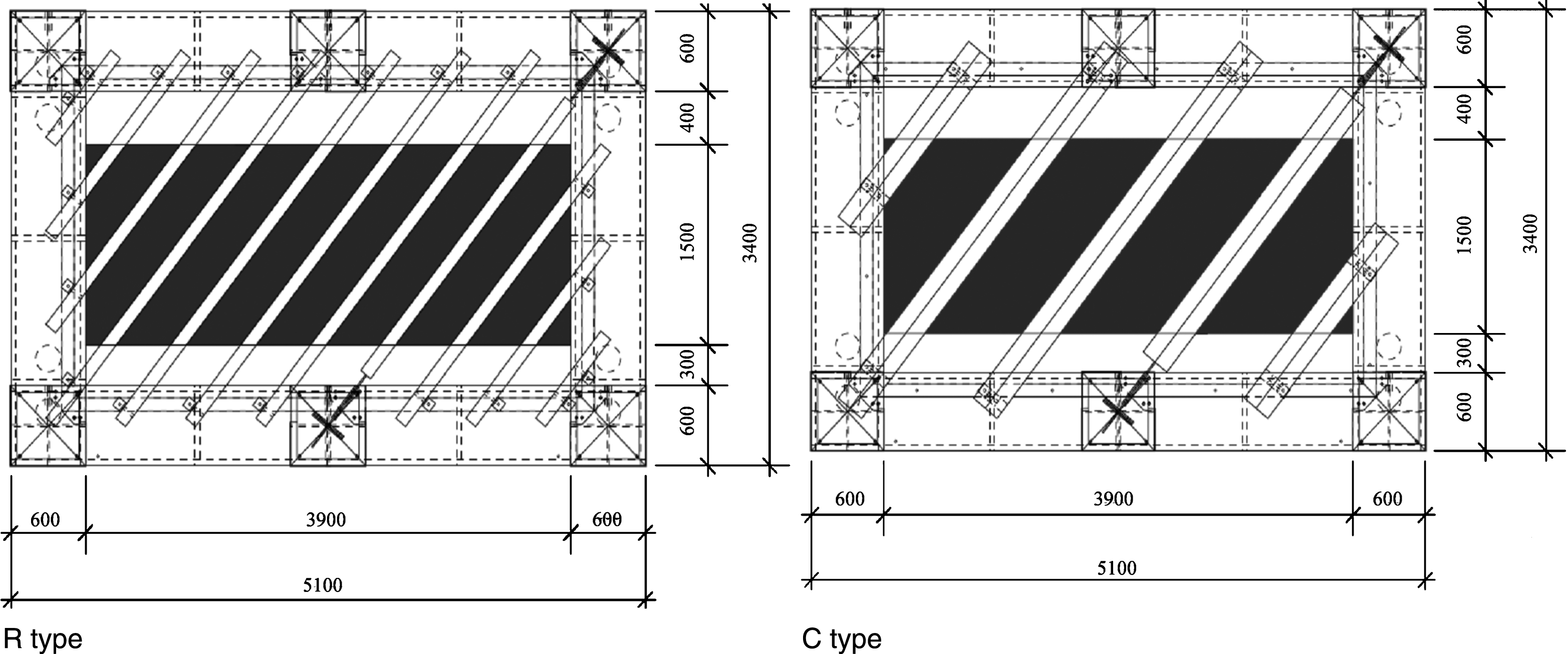
Fig.11
Surrounding condition of measurement locations.
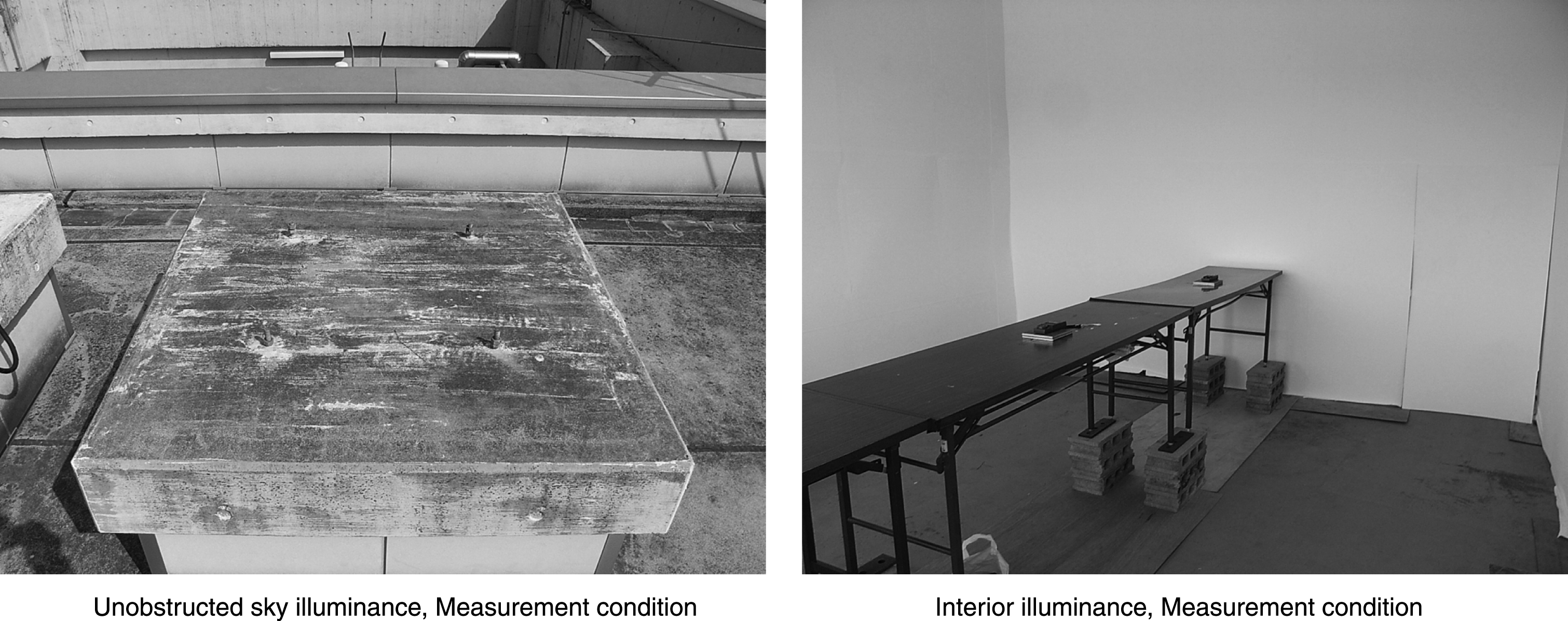
Fig.12
Interior illuminance measurement points.
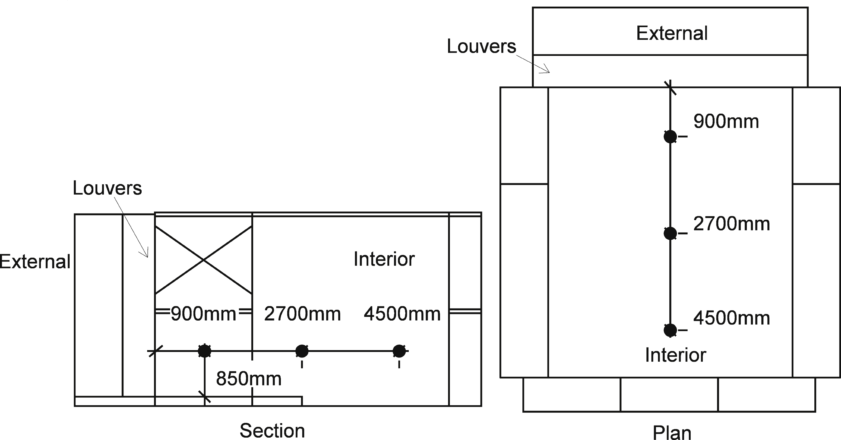
Fig.13
Measurement results (daylight factor % ).
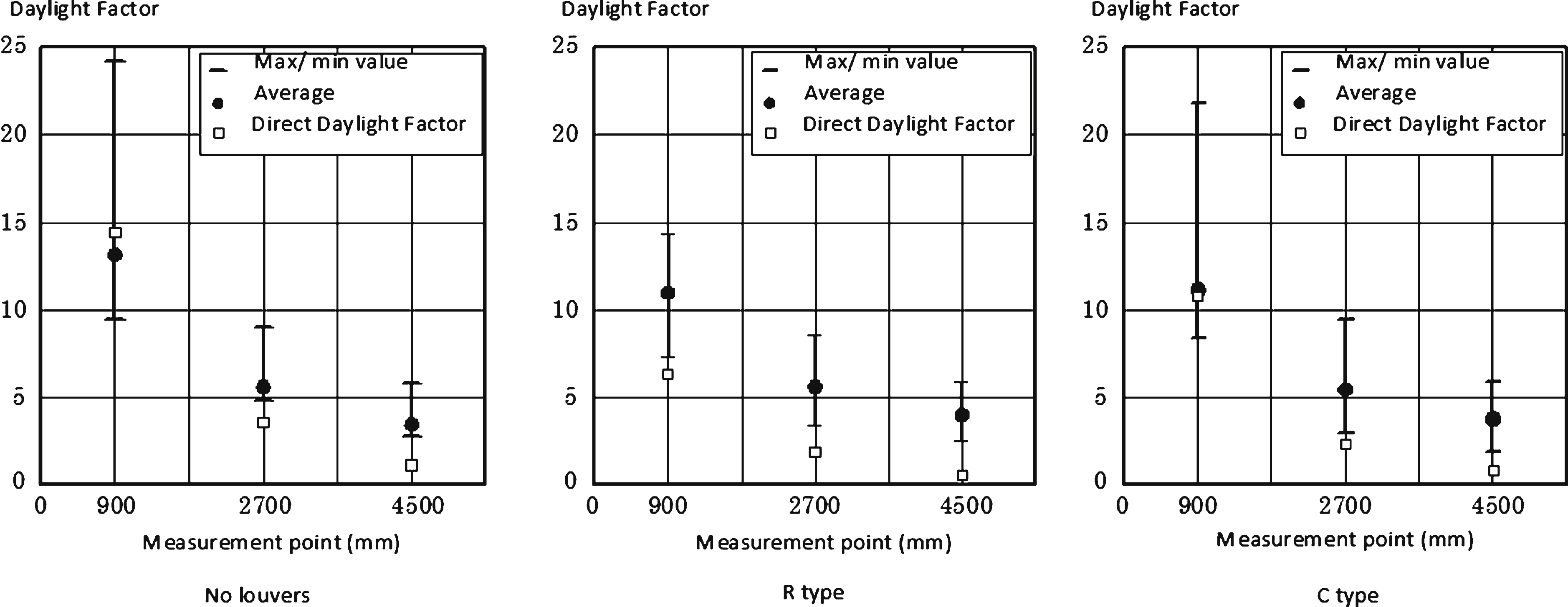
Fig.14
Interior illuminescence analysis model.
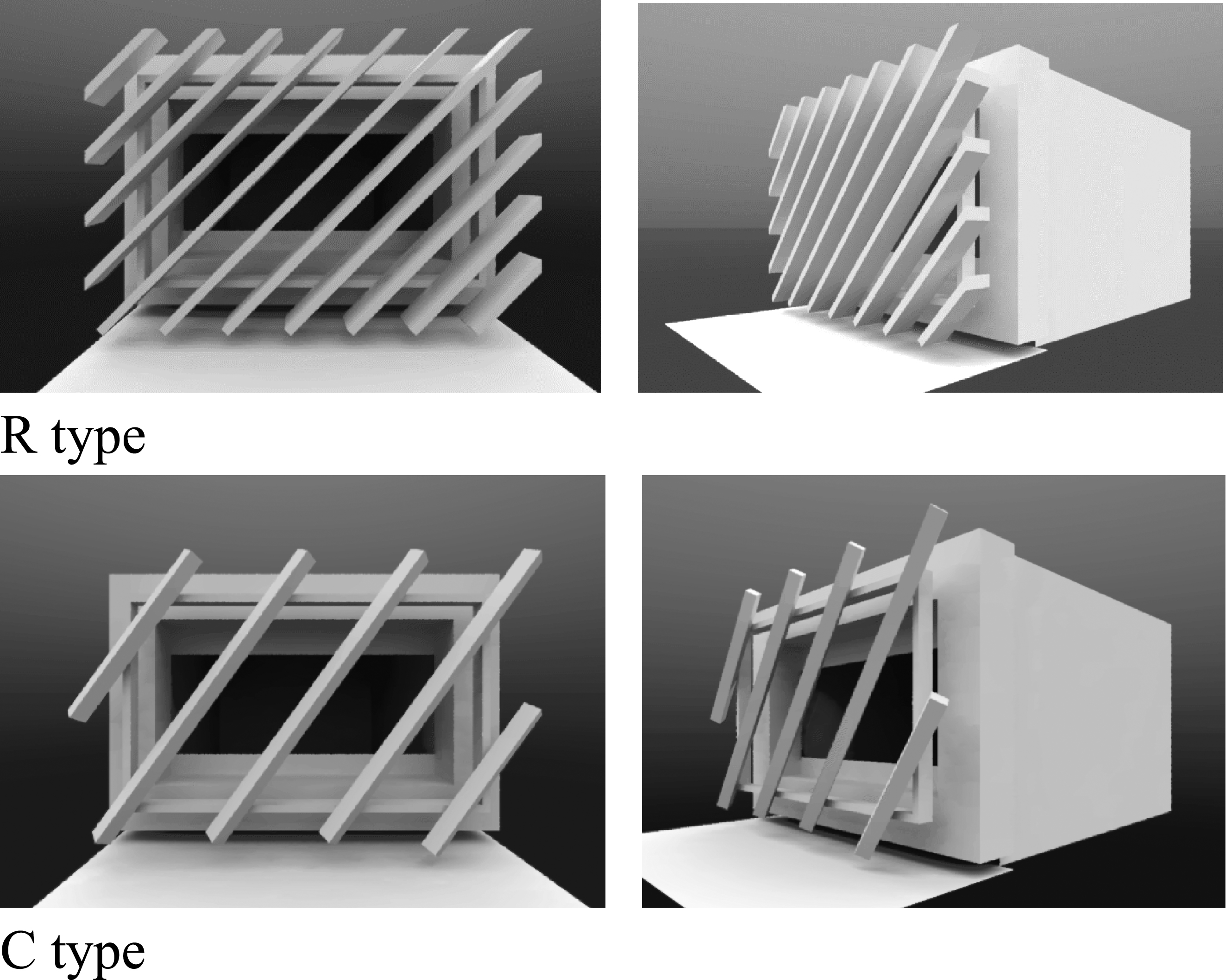
Fig.15
Comparison of experiment and analytical values (Daylight Factor % ).
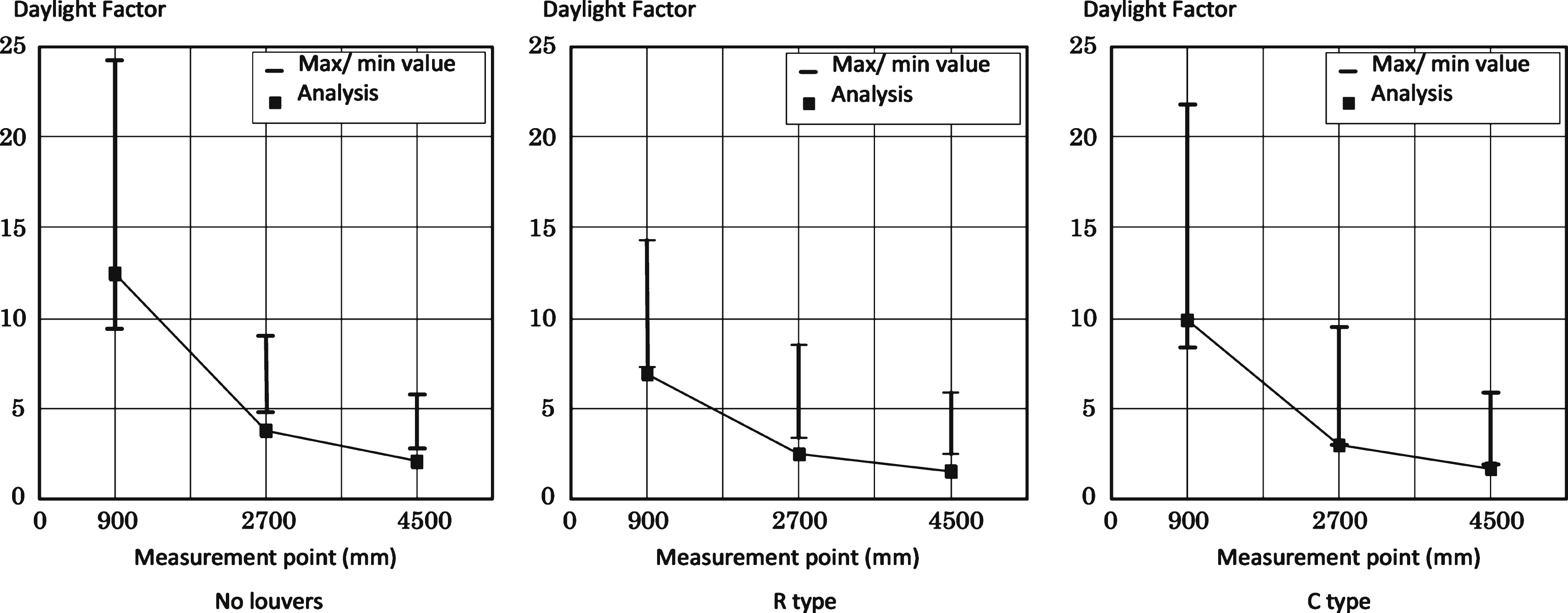
Fig.16
Interior illuminance distribution (analytical value, unit: lx). (Vertical axis indicates the distance from window; horizontal axis indicates distance from the central axis of the window).
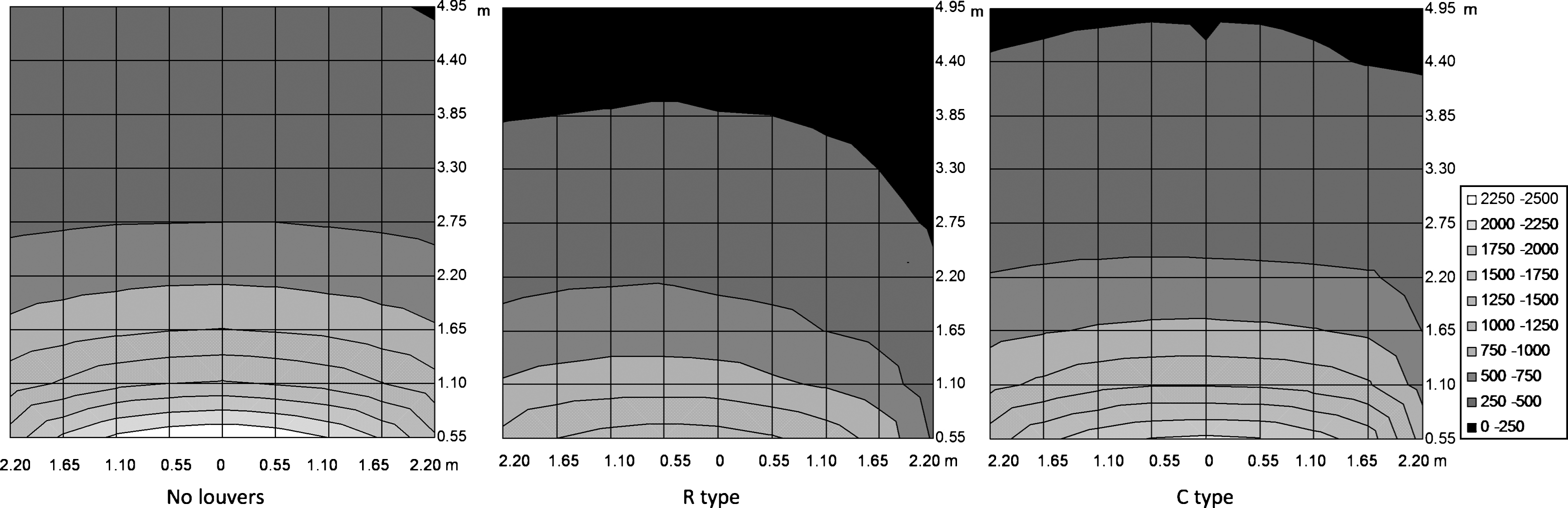
Table 1
Overview of the diagonally arranged louvers
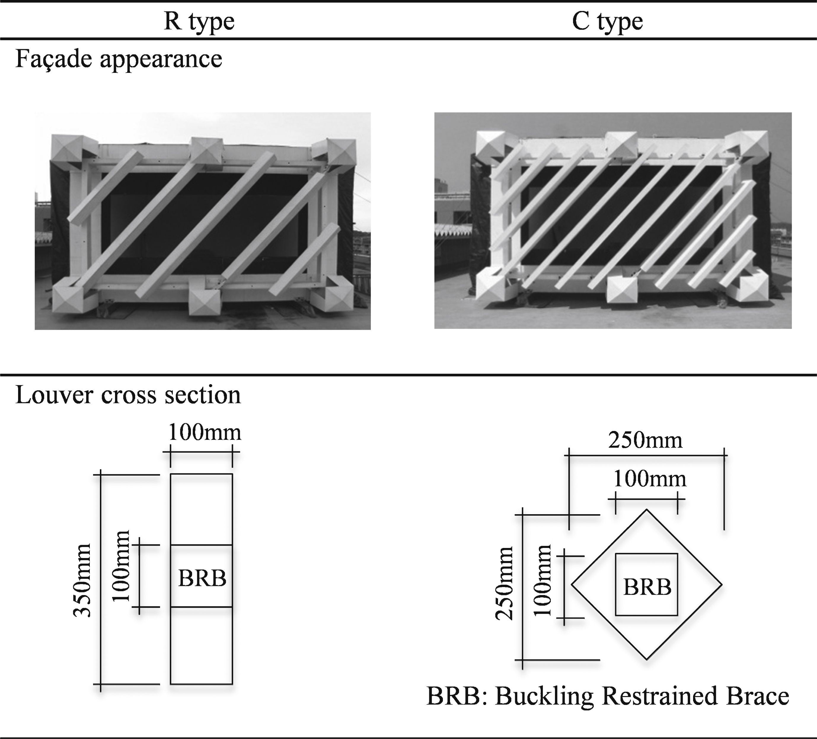 |
Table 2
Experiment conditions
| Item | Illumination measurement condition |
| Weather | Clear or cloudy |
| Measurement dates | No louvers: 18th 19th March, 2008 |
| R type: 29th March, 1st April, 2008 | |
| C type: 22nd 27th March, 2008 | |
| Measurement location | 35.29°N, 139.37°E |
| Unobstructed sky illuminance: Kanagawa University Building No. 23 rooftop | |
| Interior illuminance: Kanagawa University Building No. 12 rooftop | |
| Measuring Instruments | Digital illuminometer: TOPCON IM-2D |
| Lens: IM-2D scaling factor filter (10M) | |
| Measurement interval | Every 1 hour from 9 : 00 to 15 : 00 |
| Measurement room: Item | Properties |
| Shape/Dimensions | Width 4400 mm×Depth 5500 mm×Height 3450 mm |
| Opening direction | North |
| Opening dimensions | Width 3900 mm×Height 1500 mm |
| Retaining wall height 900 mm, spandrel wall height 1000 mm | |
| Ceiling finish | White wall paper: Munsell color N9.3 |
| Wall finish | White wall paper: Munsell color N9.3 |
| Floor finish | Concrete: Munsell color N5.5 |
| Opening finish | No glass or fittings inserted |
| Louver: Item | Properties |
| Shape/Dimensions | R type: (Left figure of Fig. 6) C type: (Right figure of Fig. 6) |
| Attachment pitch | R type: @562.5 mm (span/8) C type: @1125 mm (span/4) |
| Opening shading rate | R type: 22.68% C type: 28.76% |
| Louver finish | White coating: Munsell color N9.3 |
| Louver support frame | Rectangular cross-section 100 mm×200 mm |
| Main frame finish | White coating: Munsell color N9.3 |
Table 3
Measurement results (Illuminance lx, Daylight Factor % )
| No louvers 1st day | No louvers 2nd day | ||||||||||||||
| 900 mm | 2700 mm | 4500 mm | All Sky | Daylight Factor | 900 mm | 2700 mm | 4500 mm | All Sky | Daylight Factor | ||||||
| 9:00 | 2560 | 1472 | 957 | 16470 | 15.5 | 8.9 | 5.8 | 9:00 | 4460 | 1491 | 816 | 27400 | 16.3 | 5.4 | 3.0 |
| 10:00 | 3090 | 1570 | 1069 | 25200 | 12.3 | 6.2 | 4.2 | 10:00 | 4500 | 1811 | 1057 | 37100 | 12.1 | 4.9 | 2.8 |
| 11:00 | 3250 | 1633 | 1141 | 32500 | 10.0 | 5.0 | 3.5 | 11:00 | 2190 | 811 | 484 | 9020 | 24.3 | 9.0 | 5.4 |
| 12:00 | 3240 | 1635 | 1155 | 34400 | 9.4 | 4.8 | 3.4 | 12:00 | 839 | 295 | 164 | 5280 | 15.9 | 5.6 | 3.1 |
| 13:00 | 3300 | 1704 | 1203 | 32900 | 10.0 | 5.2 | 3.7 | 13:00 | 1620 | 602 | 338 | 10770 | 15.0 | 5.6 | 3.1 |
| 14:00 | 3300 | 1666 | 1095 | 30800 | 10.7 | 5.4 | 3.6 | 14:00 | 551 | 208 | 121 | 4140 | 13.3 | 5.0 | 2.9 |
| 15:00 | 3170 | 1500 | 997 | 25400 | 12.5 | 5.9 | 3.9 | 15:00 | 992 | 339 | 181 | 5390 | 18.4 | 6.3 | 3.4 |
| Average | 3130 | 1597 | 1088 | 28239 | 11.1 | 5.7 | 3.9 | Average | 2165 | 794 | 452 | 14157 | 15.3 | 5.6 | 3.2 |
| R type 1st day | R type 2nd day | ||||||||||||||
| 900 mm | 2700 mm | 4500 mm | All Sky | Daylight Factor | 900 mm | 2700 mm | 4500 mm | All Sky | Daylight Factor | ||||||
| 9:00 | 2275 | 1133 | 776 | 20200 | 11.3 | 5.6 | 3.8 | 9:00 | 1603 | 884 | 653 | 11210 | 14.3 | 7.9 | 5.8 |
| 10:00 | 2460 | 1268 | 871 | 24600 | 10.0 | 5.2 | 3.5 | 10:00 | 1658 | 928 | 682 | 12770 | 13.0 | 7.3 | 5.3 |
| 11:00 | 2570 | 1356 | 980 | 25300 | 10.2 | 5.4 | 3.9 | 11:00 | 1632 | 928 | 704 | 11970 | 13.6 | 7.8 | 5.9 |
| 12:00 | 3340 | 1557 | 1077 | 40800 | 8.2 | 3.8 | 2.6 | 12:00 | 1639 | 914 | 706 | 12900 | 12.7 | 7.1 | 5.5 |
| 13:00 | 3130 | 1498 | 1010 | 39100 | 8.0 | 3.8 | 2.6 | 13:00 | 1730 | 1042 | 695 | 12300 | 14.1 | 8.5 | 5.7 |
| 14:00 | 2590 | 1225 | 888 | 35700 | 7.3 | 3.4 | 2.5 | 14:00 | 2440 | 939 | 756 | 20200 | 12.1 | 4.6 | 3.7 |
| 15:00 | 3150 | 1477 | 939 | 26800 | 11.8 | 5.5 | 3.5 | 15:00 | 2150 | 1059 | 777 | 18900 | 11.4 | 5.6 | 4.1 |
| Average | 2788 | 1359 | 934 | 30357 | 9.2 | 4.5 | 3.1 | Average | 1836 | 956 | 710 | 14321 | 12.8 | 6.7 | 5.0 |
| C type 1st day | C type 2nd day | ||||||||||||||
| 900 mm | 2700 mm | 4500 mm | All Sky | Daylight Factor | 900 mm | 2700 mm | 4500 mm | All Sky | Daylight Factor | ||||||
| 9:00 | 1986 | 1093 | 772 | 15400 | 12.9 | 7.1 | 5.0 | 9:00 | 3610 | 1354 | 837 | 35800 | 10.1 | 3.8 | 2.3 |
| 10:00 | 1975 | 1118 | 785 | 17700 | 11.2 | 6.3 | 4.4 | 10:00 | 4450 | 1688 | 1015 | 48400 | 9.2 | 3.5 | 2.1 |
| 11:00 | 1984 | 1149 | 833 | 18600 | 10.7 | 6.2 | 4.5 | 11:00 | 3950 | 1426 | 886 | 46800 | 8.4 | 3.0 | 1.9 |
| 12:00 | 2030 | 1147 | 832 | 19700 | 10.3 | 5.8 | 4.2 | 12:00 | 1981 | 1146 | 847 | 16520 | 12.0 | 6.9 | 5.1 |
| 13:00 | 2180 | 1227 | 879 | 20700 | 10.5 | 5.9 | 4.2 | 13:00 | 2220 | 1231 | 902 | 17140 | 13.0 | 7.2 | 5.3 |
| 14:00 | 2210 | 1211 | 860 | 19200 | 11.5 | 6.3 | 4.5 | 14:00 | 3490 | 1561 | 998 | 26000 | 13.4 | 6.0 | 3.8 |
| 15:00 | 2340 | 1216 | 831 | 17530 | 13.3 | 6.9 | 4.7 | 15:00 | 2890 | 1255 | 780 | 13280 | 21.8 | 9.5 | 5.9 |
| Average | 2101 | 1166 | 827 | 18404 | 11.4 | 6.3 | 4.5 | Average | 3227 | 1380 | 895 | 29134 | 11.1 | 4.7 | 3.1 |
Table 4
Average and maximum/minimum values of daylight factor (% )
| No louvers | R type | C type | ||||||
| 900 mm | 2700 mm | 4500 mm | 900 mm | 2700 mm | 4500 mm | 900 mm | 2700 mm | 4500 mm |
| 2 day average | 2 day average | 2 day average | ||||||
| 13.2 | 5.6 | 3.5 | 11.0 | 5.6 | 4 | 11.2 | 5.5 | 3.8 |
| 2 day maximum value | 2 day maximum value | 2 day maximum value | ||||||
| 24.3 | 9.0 | 5.8 | 14.3 | 8.5 | 5.9 | 21.8 | 9.5 | 5.9 |
| 2 day minimum value | 2 day minimum value | 2 day minimum value | ||||||
| 9.4 | 4.8 | 2.8 | 7.3 | 3.4 | 2.5 | 8.4 | 3.0 | 1.9 |
Table 5
Summary of experiment results
| Measurement point | Average daylight factor | Variance between average daylight factor and direct daylight factor |
| 900 mm | No louver case is the highest, R type is the lowest | Average daylight factor is equal to the direct daylight factor for no louvers and C type. R type is largest since it has a lot of louvers |
| 2700 mm | No great variation in any cases | Average daylight factor exceeds the direct daylight factor in all cases |
| 4500 mm | Lover cases are higher than no louver | Average daylight factor exceeds direct daylight factor in all cases and the variation is large when louvers are installed |
Table 6
Analysis conditions
| Sky conditions | CIE standard ovarcast sky, unobstructed sky illuminance 15,000lx |
| Surrounding area | No obstructions in the surrounding area |
| Number of analytic daylight beams | 4096 (Maximum value) |
| Number of daylight reflections | 8 (Maximum value) |
| Room shape/dimensions | Width 4700 mm×Depth 5500 mm×Height 3475 mm |
| Opening position/dimensions | North elevation /Width 3900 mm×Height 2200 mm |
| Ceiling, walls, louvers, main frame finish | Off-white paint; R 0.691 G 0.696 B 0.615 (reflectance 68.8% ) |
| Floor finish | Concrete; R 0.244 G 0.194 B 0.145 (reflectance 20.3% ) |
| Opening | No glass or fittings installed |

