
Force and water jet impact reduction on adjacent structures by means of free surface breakwaters
Abstract
In head waves, water jet impacts due to run up can occur as a result of the structural configuration of some floating structures, reducing workability. Wave attenuation near the floater may reduce the risk of water jet impacts. This paper presents a numerical study of the performance and attenuation mechanisms of various plate type fixed free surface breakwaters and their ability to prevent water jet impacts on adjacent structures. Simulations are performed in two dimensions with a numerical method based on the Navier–Stokes equations in the presence of a free surface. The breakwater models are evaluated in two irregular sea states in terms of wave transmission, reflection and energy dissipation and by their ability to reduce water jets impacts on adjacent structures. A 60 degree inclined plate is found to induce a large wave energy reduction, little wave transmission and reflection and to experience little wave loading while effectively reducing water jet impacts.
1.Introduction
Some floating structures [1] are configured with a recess in the hull, an open, often square area in which work can take place with some protection against wind and waves. One could compare it to a moonpool that is not entirely enclosed by the hull, but open to the sea on one side. The workability of this type of floater is reduced due to the occurrence of strong water jets at the closed end of the recess that compromise the integrity of structures or equipment located in the slot or recess in higher waves . More vessels are in development with a slot or recess in the hull, for example for monopile installation [24]. It is important to investigate the circumstances under which water jets form and what can be done to prevent them.
Peregrine and Cooker studied the occurrence of vertical water jets as a result of wave interaction with a vertical wall [6,18]. When a wave hits the wall at the moment it would have overturned without the wall present, wave run up leading to a vertical water jet can occur at the wall. This effect is characterized by very high pressures in the fluid. Cooker and Peregrine call this effect flip-through. Ravindar et al. found that when a seaward curved parapet is installed at the top of the wall, flip-through leads to a deflected water jet and large forces on the top part of the wall [20].
Wave attenuation before the waves arrive at the end of the recess could prevent water jets, as they mainly occur for larger waves. For the protection of areas such as harbors, marinas and aquaculture from waves, use is made of breakwaters. Floating breakwaters are applicable in deep water and for a broad range of wavelengths. Floating breakwaters are usually moored to the seabed with mooring lines. Different studies found that more horizontally inclined and stiffer mooring lines, or fixed breakwaters rather than floating breakwaters, yield a better wave attenuation performance [12,14,21]. Potential configurations of shallow draft floating breakwaters interacting with (extreme) waves were considered experimentally by Bos and Wellens [4,5].
Fixed free surface breakwaters are generally fixed on piles when used for coastal protection. Teh et al. assessed different types of fixed free surface breakwaters based on their wave attenuation performance, wave reflection, energy loss, effective mass and installation cost [23]. A plate type scored lowest on costliness and mass but comparatively high on energy loss, wave reflection and wave attenuation. Whereas the orientation of the plate can be horizontal in the free surface as in Xu and Wellens [31], the scope of this study is limited to surface-piercing plate-type breakwaters.
Incident wave energy of a wave passing a breakwater can be described as the sum of transmitted, reflected and dissipated energy [15]
Here,
Different theoretical approaches exist for the purpose of estimating the transmission coefficient of a vertical plate type fixed free surface breakwater. Ursell formulated an approach using the modified Bessel functions of the first and second kind [25]. Wiegel devised a power transmission theory for estimating the transmission of a fixed vertical plate [30], which Kriebel and Bolmann later modified by accounting for partial wave reflection effects [11].
A plate type fixed free surface breakwater dissipates energy through wave overtopping, breaking, return flow and disturbance of the wave orbital path [32].
A vertical plate breakwater largely attenuates waves through wave reflection. It is expected that the breakwater experiences a lower mean continuous loading when it attenuates waves through wave energy dissipation rather than reflection [13]. An inclined plate can induce run-up and, hence, more wave breaking compared to a vertical plate, yielding larger wave energy dissipation and thus a smaller mean net force on the breakwater. However, an increase in wave breaking may increase transient forces [32].
Few studies on inclined plate type fixed free surface breakwaters were found. Rao et al. experimentally investigated the wave attenuation performance of a plate under varying angles [19]. They found that a vertical plate performed best, followed by a plate either under a 60 or 150 degree angle. It is unknown to what degree these results were influenced by the varying draft of the plate when it had a different angle and thus a different distance to the bottom of the tank, which was relatively shallow. Studies into breakwater performance are recommended to be performed in irregular rather than regular waves [16]. Different studies found deviations in the transmission coefficient as well as in the loss and reflection coefficients for the two different tested conditions [22].
The objective of this study is to address the gap with regard to deep-water performance of inclined-plate breakwaters by evaluating the performance and mechanisms of such breakwaters in irregular waves, as well as assessing their potential for reducing the risk of water jet impacts on adjacent structures in floater with a recess.
2.Methodology
2.1.Numerical method
Use is made of a numerical method that is based on the Navier–Stokes equations with a Volume-of-Fluid approach for the free surface [10,26]. The Navier–Stokes equations describe the conservation of mass
The method is comparatively fast because of the use of local generating and absorbing boundary conditions [7,8] that take care of sending irregular waves into the domain while at the same time preventing re-reflection of reflected and transmitted waves. Local boundary conditions in this approach replace wave dissipation zones that require a significantly larger domain.
The solver has been validated to properly model violent free-surface flows such as wave interaction with breakwaters [28], sloshing [3,27], wave run-up [17,29], green water impacts [2]. This makes it suitable for estimating breakwater induced wave energy dissipation by wave breaking, wave run up and overtopping, return flow and the disturbance of the wave orbital path. Simulations performed with the method will be used to evaluate different breakwater models in terms of their wave attenuation performance based on these dissipating mechanisms and wave reflection.
To solve the equations they are discretised in time using a forward Euler method. In space they are discretised by means of a finite volume method on a fixed Cartesian grid. The Courant–Friedrichs–Lewy (CFL) condition ensures stability and is adjusted dynamically in every time step.
2.2.Simulation setup
Four types of simulations are performed:
1. Without any geometry in the domain for the undisturbed waves.
2. With a breakwater to protect the hull, but without the hull present.
3. With the hull only.
4. With a breakwater and the hull.
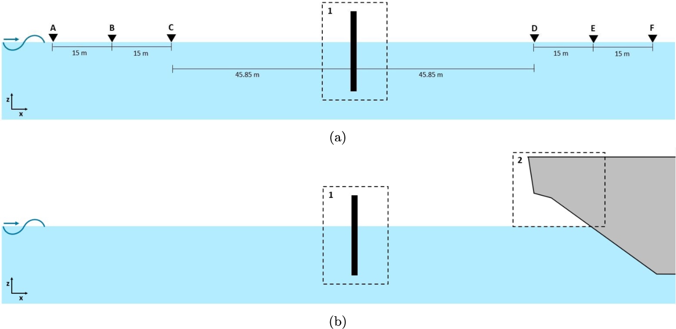
The fourth type of simulation represents a side view of the middle of the recess in the hull of the floating structure in waves, therefore the adjacent structure is referred to as the hull. Figure 1 shows a schematic view of the simulation setup for the simulations with only a breakwater (a) and with breakwater and hull (b).
The simulations are performed in two dimensions. Both breakwater and structure are fixed. Waves come in at a 0 degree angle with respect to the axis system in Fig. 1 (head waves). The draft of the hull is
The wave gauges are indicated with triangles and letters in Fig. 1. The net force is measured on the breakwater and on the hull above the waterline, these areas are indicated with dashed boxes and numbers.
Fig. 1.
Cross-section of the recess: set up for simulations with only a breakwater in the recess (a) and with breakwater in the recess and part of the hull in the recess (b).
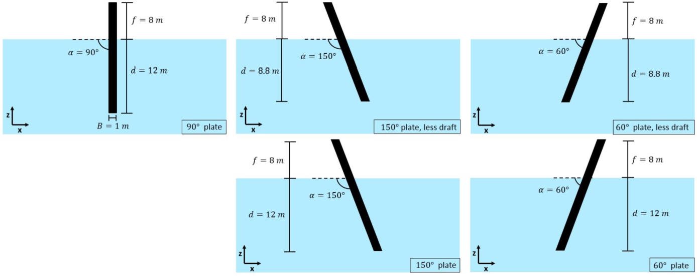
Five different breakwater models are evaluated, their particulars are listed in Fig. 2. A vertical plate is tested, two plates under a 150 degree and 60 degree angle with the same length as the vertical plate and thus a smaller draft and two inclined plates under the same angles but with the same draft as the vertical plate. The incline plate breakwaters are designed to increase the amount of dissipation through wave breaking, so to increase coefficient
The breakwaters are tested in two irregular sea states, sea state 1 with peak period
Fig. 2.
Five tested breakwater models and their particulars.
2.3.Computational grid
The grid size is chosen based on a convergence study on the significant wave height. Table 1 shows the different grids and their characteristics. The table lists the number of cells in the main directions, the smallest cell size that is a measure of the quality of the grid, the total number of cells that is a measure of the required computational effort and the amount to which stretching is applied. Stretching can be a way to reduce the computational effort, without compromising numerical accuracy where it is most needed. The finest cells in vertical direction are chosen near the mean free surface position. The stretching factor indicates how much larger the adjacent cell is with respect to its neighbour in vertical direction. No stretching in horizontal direction is used, because that would limit the accuracy of wave propagation.
Table 1
Computational grids
| Name | Stretching [%] | |||||
| s1 | 80 | 40 | 2.00 | 2.00 | 6056 | 1.06 |
| s2 | 160 | 80 | 1.00 | 1.00 | 23756 | 1.03 |
| s3 | 320 | 160 | 0.500 | 0.500 | 94496 | 1.015 |
| s3.5 | 480 | 240 | 0.250 | 0.250 | 217952 | 1.010 |
| s4 | 640 | 320 | 0.125 | 0.125 | 377984 | 1.007 |
| s5 | 1280 | 640 | 0.0613 | 0.0613 | 1758592 | 1.004 |
Fig. 3 shows a visual representation of the convergence. Grid size s5 is small enough to be considered converged. It is therefore used to calculate the relative error in significant wave height of the other grid sizes. The grid sizes (not including s3.5) exhibit monotonic convergence for the value of the wave height before the breakwater with a discriminating ratio (R) smaller than 1 for different combinations of three grid sizes, each a factor 2 smaller than the other [9].
Fig. 3.
Grid convergence evaluated through the error in the value between the significant wave height obtained on different grids, with grid s5 as a reference.
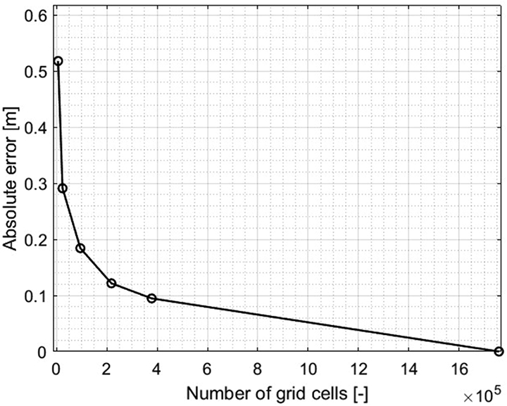
Grid size s3 is used for the simulations, because it is the best compromise between error and computation time. The error of less than
2.4.Post-processing
In the different simulations the wave elevations at each of the six wave gauges are measured as well as the force on the breakwater and on the hull when present. The measured wave signals are decomposed into their Fourier components and interpolated using a Piecewise Cubic Hermite Interpolating Polynomial (PCHIP). The average amplitude is obtained for each component from three wave gauges located before and after the breakwater. This data is used to calculate the energy density spectra and determine the significant wave height before and after the breakwater. To calculate the transmission coefficient
The reflection coefficient
Finally, the loss coefficient is calculated using Eq. (2) in the introduction.
The net force on the breakwater is measured for every simulation. As for most breakwaters this force signal contains noise, a Butterworth filter is applied to each to separate the cyclic force from the transient forces. The order of the filter that is used is 1 and the cutoff frequency is 1 rad/s for the force on the breakwater and 4 rad/s for the force on the hull.
The water jets in the simulations are quantified by the net force on the hull above the waterline. With the reduction of this force through the use of a breakwater, a link is made between breakwater performance and jet reduction.
3.Results and discussion
3.1.Comparison with theoretical models
The results for the vertical plate are compared to theoretical predictions in order to validate the results. Figure 4 displays the measured and theoretically predicted transmitted wave spectra for the vertical plate in both sea states. The theoretical spectra are calculated as response spectra of the incident wave spectrum for a simulation without a breakwater or hull.
Fig. 4.
Transmitted spectra compared with theoretical models.
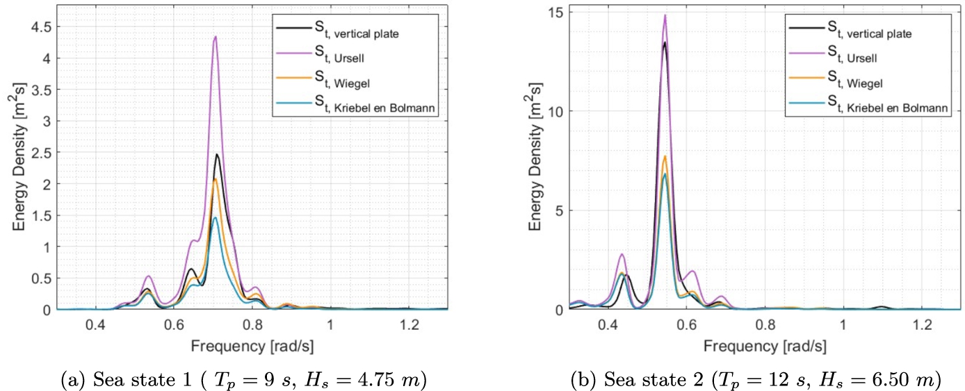
In the first sea state the transmission past the vertical plate is comparable to the predicted transmission by Wiegel [30], especially at lower frequencies. At higher frequencies it resembles Ursell [25]. The wave transmission of sea state 2 is most similar to that as predicted by Ursell, even though Ursell slightly overpredicts the wave transmission for several frequency ranges.
In longer waves, either a wider or more energy dissipating breakwater model is required to obtain the same wave transmission as for shorter waves. In sea state 1 the most energetic waves are about
3.2.Wave attenuation performance and mechanisms
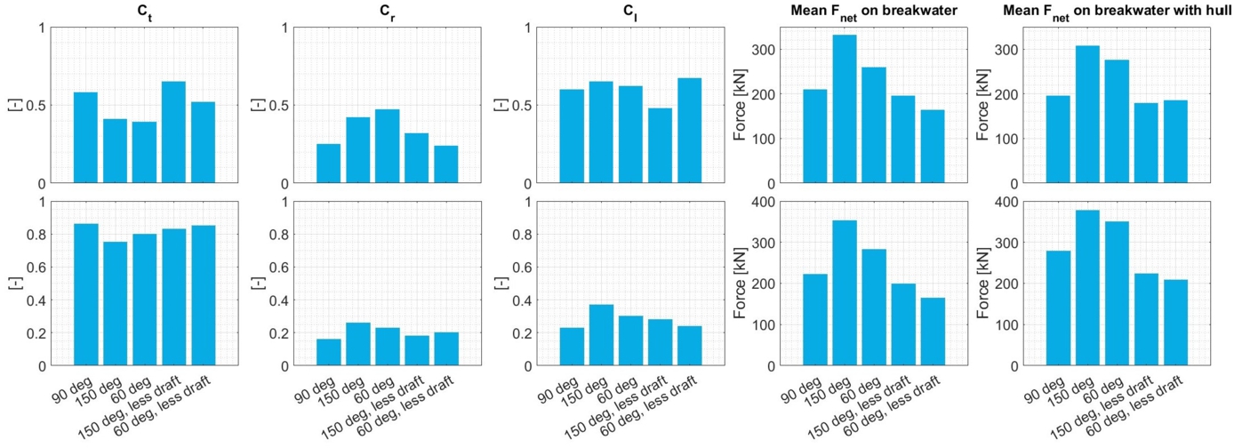
Figure 5 presents an overview of the transmission, reflection, and loss coefficients for each model, along with the mean filtered net force on the breakwater in the simulations with and without the hull present. The following observations are made:
The two inclined plates with the same draft as the vertical plate have the best wave attenuation performance in both sea states; their wave transmission is smallest. Which of the two performs best differs per sea state. Both have the largest wave reflection coefficients and experience the largest mean forces as a result of their larger draft than the other inclined plates.
The smaller 60 degree plate has a better wave attenuation performance than the vertical plate in both sea states. Part of this is likely caused by an increase in wave energy loss for the inclined plate, seen as the loss coefficient is larger in both sea states. This is a conclusion contrary to the findings of Rao et al. [19]. It should however be noted that their study was performed in shallow water with the vertical plate spanning almost the entire water column, whereas these simulations are performed in deep water conditions.
When comparing the wave forces on the plate breakwaters, we find that the wave force mainly depends on the length of the breakwater: the longer breakwaters experience a longer force. The significance hereof is that a trade-off or an optimization need to be performed: a longer breakwater features less wave transmission, but – on the other hand – also experiences a larger force that needs to be transferred into the hull.
Fig. 5.
Coefficients and forces for sea state 1 (
3.3.Water jet mitigation
In sea state 1, nine water jets are observed, in sea state 2 six are observed. Figure 6 shows a view of the first water jet of sea state 1 and the prevention thereof by the 60 degree inclined plate with a smaller draft.
Fig. 6.
Snapshot of the first water jet of sea state 1 (a) and the prevention thereof by the smaller 60 degree inclined plate (b).
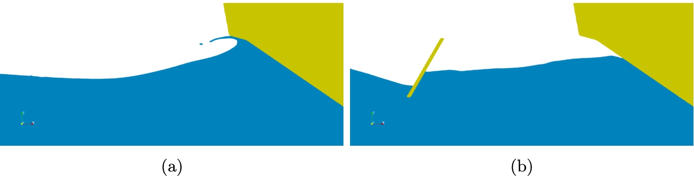
Table 2 shows for each of the models whether or not they prevent the different jets in the sea states from happening. This does not say anything about the reduction of the jet. The reduction of the water jets is represented by the reduction in the force on the hull. Panels (a) and (b) of Fig. 7 show the average reduction in the force on the hull corresponding to the water jets, for each breakwater.
Table 2
An overview for each breakwater model for both sea states if a water jet is prevented from happening (no colour) or not (red)
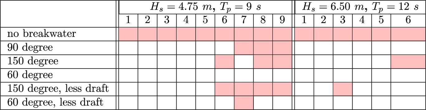
For both sea states, in nearly all cases, the breakwaters with inclined plates perform better than the vertical plate breakwater. In sea state 1 the 60 degree plates perform best in terms of wave transmission, force on the breakwater, reduction of the force on the hull and water jet prevention. Even though the 150 degree plates perform better in sea state 2 than the 60 degree models, they do not, at the same time, prevent water jets from occurring as well. The vertical plate prevents the jets as well but causes less reduction of the force on the hull.
Fig. 7.
Average reduction in the mean net force on the hull and its correlation with respect to the transmission coefficient.
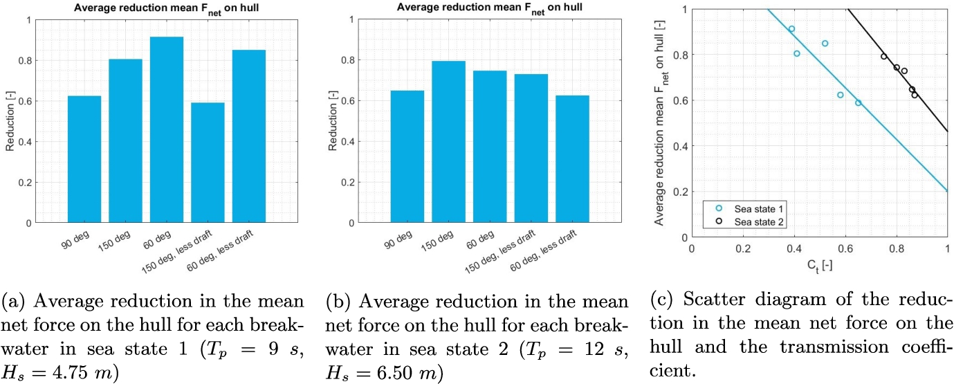
The reduction of the net force on the hull is shown as a function of
There is no direct correlation between the transmission coefficient and the prevention of water jets, as the occurrence of water jets depends on the phase and shape of the waves as well as on their height. This is demonstrated by the fact that in sea state 2, the model with the lowest transmission coefficient still does not prevent the third water jet, see Table 2.
4.Conclusions
In head waves, wave run up and water jets can occur inside recesses in the hulls of floating structures, reducing workability. With the goal of mitigating the risk, five different plate-type fixed free surface breakwater models are evaluated in terms of wave transmission, reflection and energy dissipation in two irregular sea states, in order to prevent water jets on an adjacent structure (the hull). Use is made of two dimensional, Navier–Stokes based numerical simulations.
Based on the obtained results, the following conclusions were found:
Inclined plate-type breakwaters perform better than vertical plate breakwaters for nearly all cases in the two sea states that were investigated.
A 60 degree inclined plate performs well in terms of wave energy dissipation, wave transmission, small forces on the breakwater, reduction of the force on the hull and water jet prevention. This breakwater is favourable over a 150 degree inclined plate for the application of mitigating water jet impacts.
There is a negative linear correlation, in the working range of investigated transmission coefficients, between the attenuation performance of breakwaters in a setting without the hull and their ability to reduce the force on the hull. If the transmission coefficient of a breakwater is large, the force reduction is small and vice versa.
There is no direct correlation between the transmission coefficient and the prevention of water jets for the irregular sea states that were considered. The occurrence of water jets seems to depend on the phase and shape of the waves as well as their height.
Further optimisation of the geometry of the 60 degree plate and addition of porosity and appendages is recommended to increase energy dissipation and reduce forces on the breakwater. Additionally, a statistical analysis of water jets is recommended to find a more concise relationship between forces on the hull and the occurrence of jets and hence a relationship between breakwater performance and jet mitigation. It also needs to be considered that wave breaking in reality has 3D features; the significance of the 3D features on the impact pressures needs to be investigated in future.
Acknowledgements
The authors would like to thank Anna Boon, Jovana Jovanova and Apostolos Grammatikopoulis for their feedback to this work.
Funding
The authors report no funding.
Conflict of interest
P.R. Wellens is an Editorial Board Member of this journal, but was not involved in the peer-review process nor had access to any information regarding its peer-review. The authors have no other conflicts of interest to report.
Author contributions
K.J. Holkema had access to the data and was involved in: conception; performance of work; interpretation of data; writing the article.
C. Aalbers had access to the data and was involved in: conception.
P.R. Wellens had access to the data and was involved in: conception; performance of work; interpretation of data; writing the article.
References
[1] | Allseas, Pioneering Spirit, (2023) , https://allseas.com/equipment/pioneering-spirit-offshore-construction-vessel/. |
[2] | A.D. Boon and P.R. Wellens, Probability and distribution of green water events and pressures, Ocean Engineering 264: ((2022) ), 112429. doi:10.1016/j.oceaneng.2022.112429. |
[3] | R.W. Bos, M. van der Eijk, J.H. den Besten and P.R. Wellens, A reduced order model for fsi of tank walls subject to wave impacts during sloshing, International Shipbuilding Progress 69: (2) ((2022) ), 1–20. doi:10.3233/ISP-220003. |
[4] | R.W. Bos and P.R. Wellens, Fluid structure interaction between a pendulum and focused breaking waves, Physics of Fluids 33: (6) ((2021) ), 062118. doi:10.1063/5.0054426. |
[5] | R.W. Bos and P.R. Wellens, Fluid–structure interaction between a pendulum and monochromatic waves, Journal of Fluids and Structures 100: ((2021) ), 103191. doi:10.1016/j.jfluidstructs.2020.103191. |
[6] | M.J. Cooker and D.H. Peregrine, Computations of violent motion due to waves breaking against a wall, in: Proc. of the 22nd Int. Conf. of Coastal Engineering, (1990) . |
[7] | B. Düz, R.H.M. Huijsmans, A.E.P. Veldman, M.J.A. Borsboom and P.R. Wellens, An absorbing boundary condition for regular and irregular wave simulations, in: MARINE 2011, IV Int. Conf. on Computational Methods in Marine Engineering: Selected Papers, Springer, Netherlands, (2013) , pp. 31–45. |
[8] | B. Duz, R.H.M. Huijsmans, P.R. Wellens, M.J. Borsboom and A.E. Veldman, Towards a general-purpose open boundary condition for wave simulations, in: Int. Conf. on Offshore Mechanics and Arctic Engineering, Vol. 44397: , (2011) , pp. 557–565. |
[9] | L. Eça and M. Hoekstra, A procedure for the estimation of the numerical uncertainty of cfd calculations based on grid refinement studies, Journal of Computational Physics 262: ((2014) ), 104–130. doi:10.1016/j.jcp.2014.01.006. |
[10] | K.M.T. Kleefsman, G. Fekken, A.E.P. Veldman, B. Iwanowski and B. Buchner, A volume-of-fluid based simulation method for wave impact problems, Journal of Computational Physics 206: ((2005) ), 363–393. doi:10.1016/j.jcp.2004.12.007. |
[11] | D.L. Kriebel and C.A. Bollmann, Wave transmission past vertical wave barriers, in: Coastal Engineering Proceedings, Vol. 1: , (1996) . |
[12] | J.-M. Liang, Y. Liu, Y.-K. Chen and A.-J. Li, Experimental study on hydrodynamic characteristics of the box-type floating breakwater with different mooring configurations, Ocean Engineering 254: ((2022) ). doi:10.1016/j.oceaneng.2022.111296. |
[13] | M.S. Longuet-Higgins, Mean forces exerted by waves on floating or submerged bodies with applications to sand bars and wave power machines, Proc R Soc London Ser A 352: ((1977) ), 463–480. doi:10.1098/rspa.1977.0011. |
[14] | E. Loukogeorgaki and D.C. Angelides, Stiffness of mooring lines and performance of floating breakwater in three dimensions, Applied Ocean Research 27: ((2005) ), 187–208. doi:10.1016/j.apor.2005.12.002. |
[15] | S. Neelamani and J. Ljubic, Experimental study on the hydrodynamic performance of floating pontoon type breakwater with skirt walls, Journal of Offshore Mechanics and Arctic Engineering 140: ((2018) ). |
[16] | H.P. Nguyen, J.C. Park, M. Han, C.M. Wang, N. Abdussamie, I. Penesis and D. Howe, Representative transmission coefficient for evaluating the wave attenuation performance of 3d floating breakwaters in regular and irregular waves, Journal of Marine Science and Engineering 9: ((2021) ). doi:10.3390/jmse9040388. |
[17] | Z. Peng, P. Wellens, T. Raaijmakers et al., 3-d numerical modeling of wave run-up on monopiles, in: 31st Int. Conf. on Ocean, Offshore and Arctic Engineering, Vol. 5: , (2012) , pp. 327–335. |
[18] | D.H. Peregrine, Water-wave impact on walls, Annual Review of Fluid Mechanics 35: ((2003) ), 23–43. doi:10.1146/annurev.fluid.35.101101.161153. |
[19] | S. Rao, K.G. Shirlal, R.V. Varghese and K.R. Govindaraja, Physical model studies on wave transmission of a submerged inclined plate breakwater, Ocean Engineering 36: ((2009) ), 1199–1207. doi:10.1016/j.oceaneng.2009.08.001. |
[20] | R. Ravindar, V. Sriram and M. Salauddin, Numerical modelling of breaking wave impact loads on a vertical seawall retrofitted with different geometrical configurations of recurve parapets, Journal of Water and Climate Change 13: ((2022) ), 3644–3674. doi:10.2166/wcc.2022.211. |
[21] | X. Ren and K. Wang, Mooring lines connected to floating porous breakwaters, Int. Journal of Engineering Science ((1994) ), 1511–1530. doi:10.1016/0020-7225(94)90161-9. |
[22] | V. Sundar and B.V.V. Subbarao, Hydrodynamic performance characteristics of quadrant front-face pile-supported breakwater, Journal of Waterway, Port, Coastal and Ocean Engineering 129: ((2003) ), 22–33. doi:10.1061/(ASCE)0733-950X(2003)129:1(22). |
[23] | H.M. Teh, Hydraulic performance of free surface breakwaters: A review, Sains Malaysiana 42: ((2013) ), 1301–1310. |
[24] | Ulstein, Ulstein U-Stern smart monopile installation on dp, (2023) , https://ulstein.com/news/ulstein-u-stern-smart-monopile-installation-on-dp. |
[25] | F. Ursell, The effect of a fixed vertical barrier on surface waves in deep water, Mathematical Proceedings of the Cambridge Philosophical Society 43: ((1947) ), 374–382. doi:10.1017/S0305004100023604. |
[26] | M. van der Eijk and P. Wellens, Two-phase free-surface flow interaction with moving bodies using a consistent, momentum preserving method, Journal of Computational Physics 474: ((2023) ), 111796. doi:10.1016/j.jcp.2022.111796. |
[27] | M. Van Der Eijk and P.R. Wellens, A compressible two-phase flow model for pressure oscillations in air entrapments following green water impact events on ships, International Shipbuilding Progress 66: (4) ((2019) ), 315–343. |
[28] | P. Wellens and M. Van Gent, Wave-induced setup inside permeable structures, in: Int. Conf. on Coastal Engineering (ICCE), (2012) , p. 2. |
[29] | I. Wenneker, P.R. Wellens and R. Gervelas, Volume-of-fluid model comflow simulations of wave impacts on a dike, in: Proc. of 32nd Int. Conf. on Coastal Engineering, (2010) . |
[30] | R.L. Wiegel, Transmission of waves past a rigid vertical thin barrier, Journal of the Waterways and harbors division 86: (1) ((1960) ), 1–12. doi:10.1061/JWHEAU.0000153. |
[31] | P. Xu and P.R. Wellens, Fully nonlinear hydroelastic modeling and analytic solution of large-scale floating photovoltaics in waves, Journal of Fluids and Structures 109: ((2022) ), 103446. doi:10.1016/j.jfluidstructs.2021.103446. |
[32] | O. Yagci, V.S.O. Kirca and L. Acanal, Wave attenuation and flow kinematics of an inclined thin plate acting as an alternative coastal protection structure, Applied Ocean Research 48: ((2014) ), 214–226. doi:10.1016/j.apor.2014.09.003. |


