
Calculation and evaluation of load performance of magnetic levitation system in medium-low speed maglev train
Abstract
The medium-low speed maglev train is an entirely new way of transportation without wheels, and it makes the best of the attraction between the electromagnet and the F-type track to achieve levitation. The magnetic levitation system is considered as the wheels of medium-low speed maglev train, which plays a major role in bearing the weight of vehicle. The theoretical calculation and finite element numerical analysis are performed to calculate the load performance of the magnetic levitation system under different load conditions. The difference of calculation results between the two methods is analyzed and discussed. In addition, a series of load-carrying tests in vehicles operating on Changsha maglev express is carried out. The experimental results have revealed that the calculation results based on FEM are basically matched with that of actual well conditions. Therefore, the load performance of the magnetic levitation system in medium-low speed maglev train is calculated and evaluated successfully.
1.Introduction
The medium-low speed maglev train is an entirely new way of transportation without wheels, and it makes the best of the attraction between the electromagnet and the F-type track to achieve levitation. The magnetic levitation system is considered as the wheels of medium-low speed maglev train, which plays a major role in bearing the weight of vehicle. Compared with conventional metro and other railway systems, it absolutely abandons the wheel-rail relationship and actualizes non-contact motion, which not only eliminate mechanical friction to reduce noise and vibration, but also allow the medium-low speed maglev train to travel through urban buildings freely. In addition, there is no emission to atmosphere during running. Therefore, the medium-low speed maglev train is safe, sound, low-carbon and environmentally friendly. The Linimo line of the first medium-low speed maglev train line all over the world was opened in 2005. Moreover, the Incheon airport maglev of South Korea went into operation on February 3rd, 2016.
The Changsha maglev express is the first domestically medium-low speed maglev line in China, which owns the proprietary intellectual property rights completely. This line stretches over 18.55 kilometers and started commercial operations on May 6th 2016. Beijing’s 1st maglev line S1 is the second domestically medium-low speed maglev line in China and began operating on December 31st 2017. The Qingyuan maglev travel line is under construction at present, and will go into operation in September 2019. In recent years, the maglev train really starts to receive considerably increasing attention and becomes an active traffic field.
Fig. 1.
The photograph of medium-low speed maglev train in Changsha.
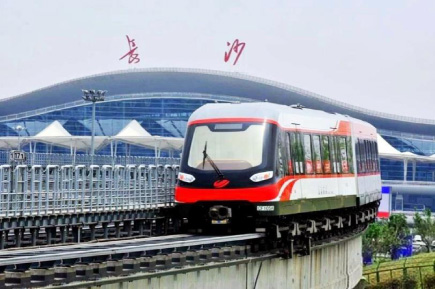
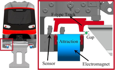
Fig. 2.
The structure of magnetic levitation system in medium-low speed maglev train.
A great number of scholars and engineers in Japan, the United States, South Korea and China are carrying out research in related fields and have already achieved many successes [1–3]. However, the research on load performance of mediumlow speed maglev train is relatively few, and it is often analyzed theoretically. In addition, due to lacking the corresponding engineering background, the calculation results are not verified. This subject is concerned chiefly with the study of calculation of load performance of the magnetic levitation system in medium-low speed maglev train. The theoretical calculation and finite element numerical analysis are performed to calculate and investigate the load performance of the magnetic levitation system under different load conditions. With the increase of load, the difference of calculation results between the two methods become larger and larger. To illustrate and verify the rationality of the foregoing calculation results, we conduct a series of load-carrying tests on vehicles operating on Changsha maglev express. The experimental results have revealed that the calculation results based on FEM are basically matched with that of actual well conditions. For the current work, it is sufficient to point out that the load performance of the magnetic levitation system in medium-low speed maglev train is calculated and evaluated successfully.
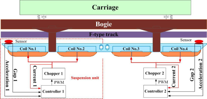
Fig. 3.
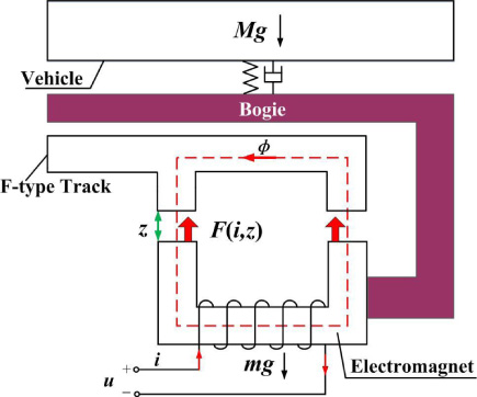
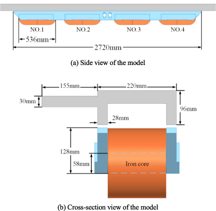
The schematic diagram of magnetic levitation system.
2.The magnetic levitation system of medium-low speed maglev train
It is well known that magnets of the same polarity tend to repel each other, whereas those of different polarity attract each other. The medium-low speed maglev train makes full use of the attraction between the electromagnet and the F-type track to achieve levitation at a desired gap [4,5]. The magnetic levitation system has three key parts: suspension controller, sensor and electromagnet. We customarily refer to it as a suspension unit. A complete medium-low speed maglev train has 20 sets of such suspension units, which distributing uniformity on the bottom of the carriage.
Fig. 4.
The three-dimensional structure of the electromagnet module.
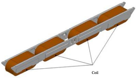
Fig. 5.
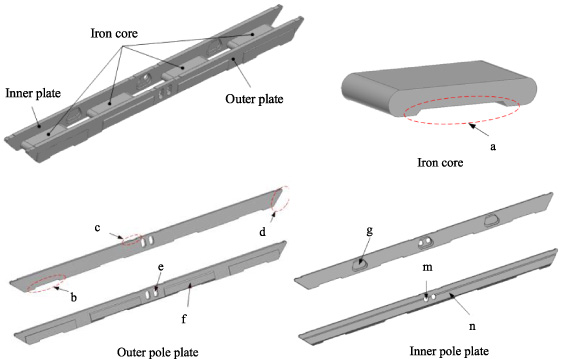
The schematic diagram of main components of electromagnet.
2.1.Working principle of magnetic levitation system
In the magnetic levitation system, a complete electromagnet module consists of two groups of electromagnets, and a group of electromagnet is composed of two coils which connected in series. The sensors measure the gap between F-type track and the electromagnet continuously. In addition, the acceleration signal and the current signal are also measured and transmitted to the suspension controller. The suspension controller calculates the control quantity according to the measured signals to produce PWM on the chopper. The chopper adjusts the current of electromagnet in real time. When the suspension current is switched on, the upward electromagnetic force is generated. The F-type track will lift the base of the vehicle, which is connected with carriage by air springs. Therefore, the medium-low speed maglev train has the ability to suspend the vehicle above the rail against the gravity. The magnetic levitation system is considered as the wheels of medium-low speed maglev train, which plays a major role in bearing the weight of vehicle. The interaction between electromagnetic force and the gravity always keeps a dynamic balance, no matter how the speed and railway line changes [6–9].
2.2.Structure parameters of electromagnet
The electromagnet is composed of inner pole plate, outer pole plate, iron core, and coil. In order to facilitate the heat dissipation, the coil is divided into two parts along the longitudinal direction [10–13]. The material of coils is aluminum. What’s more, the inner and outer plate and core are fixed by bolts. The three-dimensional structure of the electromagnet module is illustrated in Fig. 4.
In practice, considering the influence of installation, heat dissipation and weight loss, the structure of the electromagnet is illustrated in the Fig. 5. Among them, a and b are winding cooling ventilation grooves, c is anti-suction ski installation grooves, d is chamfered to facilitate sensor installation, e and m are brake clamp installation holes, f is polar plate thickening parts in order to install transverse ski and brake on the outer polar plate, g are weight reduction grooves.
The parameters of the electromagnet are indicated in Table 1.
Table 1
The parameters of the electromagnet
| Symbol | Meaning | Quantity | Unit |
| m | Mass of electromagnet | 200 | kg |
| R | Resistance | 0.92 | Ω |
| N | Number of turns | 360 | |
| A | Polar area | 0.038 | m2 |
| 𝜇0 | Vacuum permeability | 4𝜋 ×10−7 | |
| L | Length of electromagnet | 1.36 | m |
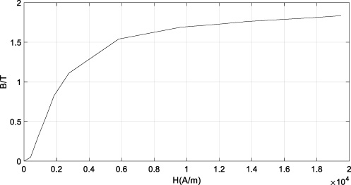
Considering the magnetic conductivity and mechanical strength, Q235B is selected as the material for the pole plate and iron core [14]. With regard to soft magnetic materials, the correlation between magnetic flux density and magnetic field strength is described in Fig. 6.
Fig. 6.
B-H curve of Q235B.
3.Theoretical calculation of load performance of magnetic levitation system
3.1.Mathematical model of magnetic levitation system
In order to analyze the load performance of the magnetic levitation system, the mathematical model of magnetic levitation system has to be established. If all factors are taken into account, the order of mathematical model will be very high. Therefore, it will lead to resolve the characteristics of the magnetic levitation system difficultly [4,5]. Therefore, plenty of minor factors are neglected:
(1) The magnetic flux leakage and edge effect are ignored, and the magnetic flux is uniformly distributed in the air gap consequently.
(2) The electromagnetic force generated by the electromagnet is considered to concentrate on the center of mass.
(3) There is no dislocation between the magnetic pole surface and the F-type track, namely, there is only vertical motion of the electromagnet relative to the track.
Fig. 7.
The mathematical model of magnetic levitation system.
The voltage and current equation of electromagnet is presented:
(1)
The electromagnetic force generated by the electromagnet is satisfied:
(2)
The dynamic equation of magnetic levitation system is as follows:
(3)
Derived from Eq. (1)–Eq. (3), the mathematical model of magnetic levitation system is obtained. The state variables are specified, and the mathematical model of magnetic levitation system is established:
(4)
According to the above discussion, it is concluded that the magnetic levitation system is typically nonlinear and controlled. By designing a qualified controller, the magnetic levitation system can work steadily in the desired state. The PID control algorithm is less dependent on the accurate model, so it is ideally situated for the magnetic levitation system. Based on the idea of cascade control strategy, the designed PID control algorithm consists of two parts. The inner loop is the current loop, while the outer loop is the position loop.
Fig. 8.
The schematic diagram of current loop.
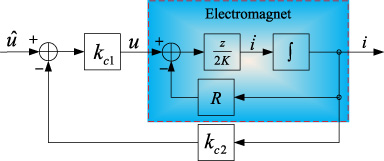
Among, the input voltage before introducing current loop is
(5)
(6)
To sum up, the PID controller of the magnetic levitation system is designed entirely. The final control law is presented:
(7)
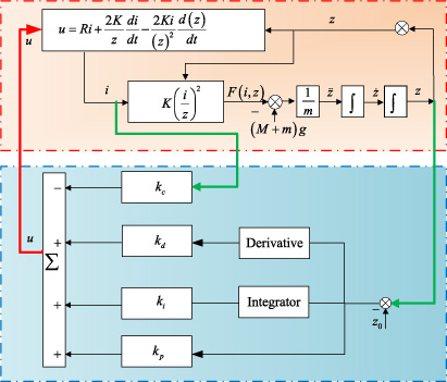
Fig. 9.
The control block diagram of magnetic levitation system.
3.2.Theoretical calculation of load performance
The medium-low speed maglev train of Changsha maglev express has three vehicles, namely, MC1,M and MC2. A complete medium-low speed maglev train has 20 sets of suspension units, distributed on the bottom of the carriage. The maglev train works in the three load conditions: noload condition (AW0), full load condition (AW2) and overload condition (AW3). The weight of the maglev train under different loads is given in Table 2.
Table 2
The weight of the maglev train under different loads
| Weight of MC | Weight of M | |
| AW0 | 24 | 23.5 |
| AW2 | 30 | 29.92 |
| AW3 | 33 | 32.92 |
According to the Table 2, the weight of MC and M vehicle is basically equal. In the following calculation, we only take the MC vehicle as an example. In order to examine the load performance of magnetic levitation system, the above three conditions are all need to be calculated and investigated.
(1) The load performance of magnetic levitation system on AW0 condition:
Fig. 10.
The control block diagram of magnetic levitation system.
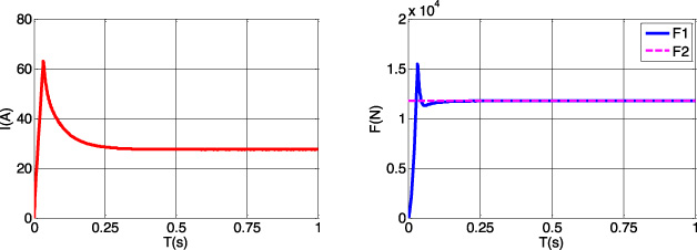
Under AW0 load condition, a whole maglev train weighs 24 tons and has 20 suspension units to provide upward support against the gravity. Therefore, each suspension unit needs to provide 11760N electromagnetic force. In order to investigate and verify whether the designed magnetic levitation system can generate the required electromagnetic force F2, we carry out simulation in the established mathematical model. As shown in Fig. 10, the suspension current increases rapidly and stabilizes at 27.5 A when the suspension unit works under AW0 condition. Moreover, the suspension unit is also able to generate electromagnetic force quickly. The final generated electromagnetic force F1 is 11760 N, which realizes the balance between electromagnetic force and gravity.
(2) The load performance of magnetic levitation system on AW2 condition:
Fig. 11.
The control block diagram of magnetic levitation system.
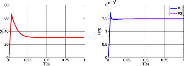
Under AW2 load condition, a complete maglev train weighs 30 tons and has 20 suspension units to provide upward support against the gravity. Therefore, each suspension unit needs to provide 14700 N electromagnetic force. In order to investigate and verify whether the designed magnetic levitation system can generate the required electromagnetic force F2, we carry out simulation in the established mathematical model. As presented in Fig. 11, the suspension current increases rapidly and stabilizes at 30.8 A when the suspension unit works under AW2 condition. In addition, the suspension unit is also able to generate electromagnetic force quickly. The final generated electromagnetic force F1 is 14700 N, which realizes the balance between electromagnetic force and gravity.
(3) The load performance of magnetic levitation system on AW3 condition:
Fig. 12.
The control block diagram of magnetic levitation system.
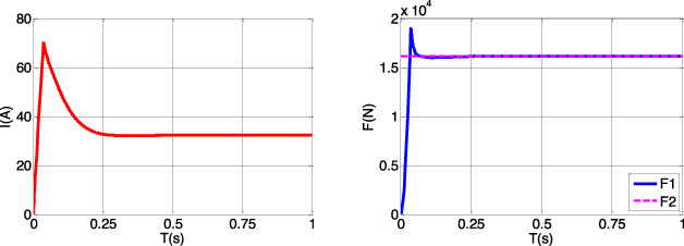
Under AW3 load condition, a complete maglev train weighs 33 tons and has 20 suspension units to provide upward support against the gravity. Therefore, each suspension unit needs to provide 16170 N electromagnetic force. In order to investigate and verify whether the designed magnetic levitation system can generate the required electromagnetic force F2, we carry out simulation in the established mathematical model. As presented in Fig. 12, the suspension current increases rapidly and stabilizes at 32.3 A when the suspension unit works under AW3 condition. In addition, the suspension unit is also able to generate electromagnetic force quickly. The final generated electromagnetic force F1 is 16170 N, which realizes the balance between electromagnetic force and gravity.
In summary, the theoretical calculation results consists of electromagnetic force and suspension current. The calculation results of MC1 train on AW0, AW2 and AW3 load condition are presented in Table 3.
Table 3
The theoretical calculation results under different loads
| Gap | Equivalent weight of vehicle | Theoretical calculation of electromagnetic force | Suspension current | |
| AW0 | 10 mm | 1200 Kg | 11760 N | 27.5 A |
| AW2 | 10 mm | 1500 Kg | 14700 N | 30.8 A |
| AW3 | 10 mm | 1650 Kg | 16170 N | 32.3 A |
4.Finite element model verification
Generally speaking, finite element model method is usually used to resolve the electromagnetic fields problems [15,16]. It is able to provide much more realistic and accurate results in order to verify the theoretical calculation results at the expense of computation cost. We adopt the professional Ansoft Maxwell based on a 64-core workstation to calculate the 3D transient magnetic field of magnetic levitation system.
4.1.Finite element model
According to the structure, size and parameters of magnetic levitation system, the following important steps are carried out to establish the finite element model.
(1) Choosing solution type
The transient analysis is selected as the simulation type in order to solve the motion problems. The operation of medium-low speed maglev train is mainly uniform linear motion. The expected result is to simulate the part entering the steady state.
(2) Establishing the model
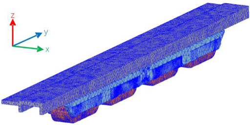
The three-dimensional model is established based on the real structure, size and parameters of magnetic levitation system. All key components including the inner pole plate, outer pole plate, iron core, and coil are designed on a 1:1 scale. The three-dimensional model of magnetic levitation system is presented in Fig. 13.
Fig. 13.
The three-dimensional model.
(3) Assigning the Materials
According to the previous presentation, the materials of iron core and inner and outer pole plates and F-type track are all Q235B. The Q235B material is selected from the repository and added to the established model.
(4) Boundary defined
Boundaries are defined to form a region, in which all operations are performed.
(5) Mesh operation
The accuracy of finite element simulation depends on the degree of mesh generation. However, mesh generation cannot be too fine, which will lead to too much computation and exceed the load of the workstation [17–19]. Considering the calculation cost, the mesh schematic of this simulation has a total number of about 250,000 meshes. The reason why 250,000 meshes is appropriate is that the calculation results are stable, and that the results are similar when the number of meshes is increased.
Fig. 14.
The mesh view of three-dimensional model.
4.2.Simulation and verification
In order to verify the load performance of magnetic levitation system, the above three conditions are all need to be calculated and investigated based on FEM. By adding the DC current excitation, the simulation results of magnetic flux density of air gap, three-dimensional magnetic field distribution and electromagnetic force are achieved on three load conditions.
(1) AW0 load condition:
Fig. 15.
The calculation results by utilizing FEM on AW0 load condition.
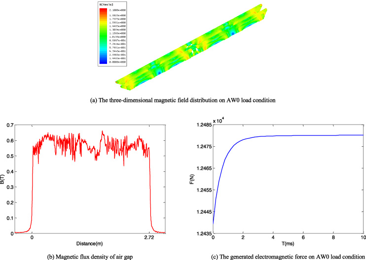
Under AW0 load condition, the excitation suspension current is 28 A, and the three-dimensional magnetic field distribution of the whole electromagnet module is presented in Fig. 15(a). There is hardly any magnetic saturation region. The curve of magnetic flux density of air gap is measured in Fig. 15(b), and the position of wave peak is corresponding to iron core. The electromagnetic force generated by the electromagnet is 12480 N.
(2) AW2 load condition:
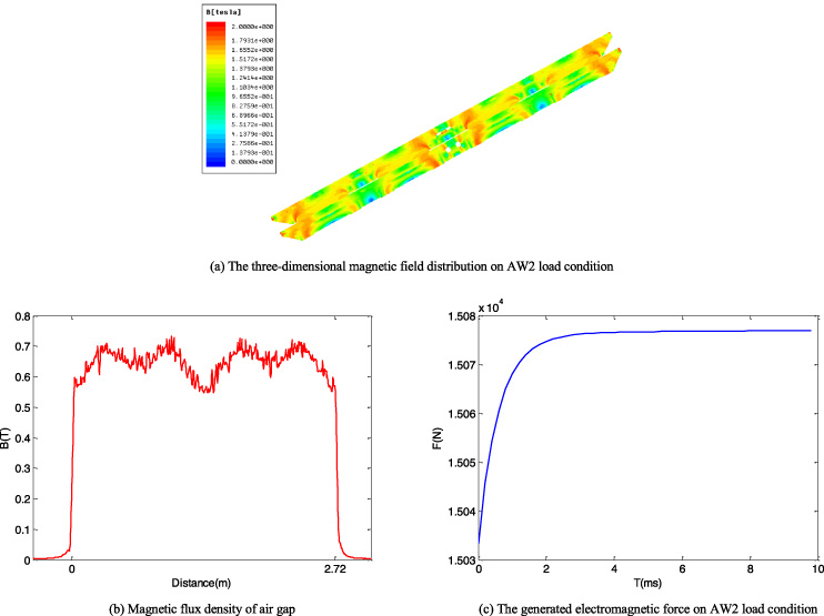
The finite element numerical analysis results on AW2 load condition are shown in Fig. 16. The excitation suspension current is 32 A. Thus, the three-dimensional magnetic field distribution of the whole electromagnet module is achieved. It is found that the magnetic saturation appears on the pole plate near the iron core, which has a bad effect on producing the upward electromagnetic force. The curve of magnetic flux density of air gap is observed in Fig. 16(b), and the position of wave peak is corresponding to iron core. What’s more, the magnetic flux density of air gap on AW2 load condition is larger than that on AW0 load condition. The electromagnetic force produced by the electromagnet is 15075 N under this circumstance.
Fig. 16.
The calculation results by utilizing FEM on AW2 load condition.
(3) AW3 load condition:
Fig. 17.
The calculation results by utilizing FEM on AW3 load condition.
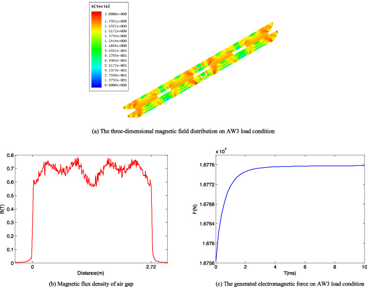
Under AW3 load condition, the excitation suspension current is 35 A. The finite element numerical analysis results on AW3 load condition are presented in Fig. 17. As shown in Fig. 17(a), the phenomenon of magnetic field saturation on the pole plate near the iron core is serious. It has a dreadful effect on generating the upward electromagnetic force. The curve of magnetic flux density of air gap is observed in Fig. 17(b), and the position of wave peak is corresponding to iron core. In addition, the magnetic flux density of air gap on AW3 load condition is the largest compared with AW0 and AW2 load condition. The electromagnetic force produced by the electromagnet is 16776 N.
In summary, The calculation results based on FEM consists of electromagnetic force and suspension current. The calculation results of MC1 train on AW0, AW2 and AW3 load condition are presented in Table 4.
Table 4
The calculation results based on FEM under different loads
| Gap | Equivalent weight of vehicle | The calculation of electro-magnetic force based on FEM | Suspension current | |
| AW0 | 10 mm | 1200 Kg | 12480 N | 28 A |
| AW2 | 10 mm | 1500 Kg | 15075 N | 32 A |
| AW3 | 10 mm | 1650 Kg | 16776 N | 35 A |
5.Experiment and test
In order to achieve the load performance data of magnetic levitation system of medium-low speed maglev train on different load conditions, a series of load-carrying tests in vehicles operating on Changsha Maglev Express Line was conducted. All the test experiments were carried out in the maintenance depot of maglev vehicle depot. The loading equal-quality sandbags were carried on the floor of the carriage to construct AW0, AW2 and AW3 load condition. It was conducive to make the load distribution relatively uniform.
After the magnetic levitation system received the floating instruction, the suspension current was switched on and the upward electromagnetic force was generated. At this time, the electromagnetic force produced by 20 suspension units lifted the vehicle to suspend above the rail against the gravity. Generally speaking, the magnetic levitation system plays a major role in bearing the weight of vehicle, which considered as the wheels of medium-low speed maglev train.
Fig. 18.
The photograph of load-carrying test in vehicles operating on Changsha Maglev Express Line.

Table 5
The experiment results under AW0 load condition
| Vehicle | Suspension unit | Gap (mm) | Suspension current (A) |
| MC1 | 1 | 10 | 30 |
| MC1 | 2 | 10.1 | 30.1 |
| MC1 | 3 | 9.9 | 30.2 |
| MC1 | 4 | 9.8 | 28.7 |
| MC1 | 5 | 9.9 | 30.3 |
| MC1 | 6 | 9.8 | 27.6 |
| MC1 | 7 | 9.7 | 26.7 |
| MC1 | 8 | 9.9 | 29.5 |
| MC1 | 9 | 9.9 | 30 |
| MC1 | 10 | 10.1 | 30.3 |
| MC1 | 11 | 10 | 30.2 |
| MC1 | 12 | 9.9 | 27.9 |
| MC1 | 13 | 9.7 | 25.1 |
| MC1 | 14 | 9.9 | 30.1 |
| MC1 | 15 | 9.7 | 28.7 |
| MC1 | 16 | 9.9 | 28.1 |
| MC1 | 17 | 9.9 | 27.3 |
| MC1 | 18 | 9.7 | 30.1 |
| MC1 | 19 | 9.9 | 29.9 |
| MC1 | 20 | 9.7 | 28 |
| Average value | 9.87 | 28.94 |
Table 6
The experiment results under AW2 load condition
| Vehicle | Suspension unit | Gap (mm) | Suspension current (A) |
| MC1 | 1 | 9.6 | 30.5 |
| MC1 | 2 | 9.7 | 33.6 |
| MC1 | 3 | 9.7 | 31.3 |
| MC1 | 4 | 9.7 | 35.1 |
| MC1 | 5 | 9.7 | 30.9 |
| MC1 | 6 | 9.7 | 32.7 |
| MC1 | 7 | 9.7 | 34.2 |
| MC1 | 8 | 9.8 | 35.8 |
| MC1 | 9 | 9.8 | 34.3 |
| MC1 | 10 | 9.8 | 34.9 |
| MC1 | 11 | 9.6 | 29.6 |
| MC1 | 12 | 9.9 | 36.2 |
| MC1 | 13 | 9.8 | 35.8 |
| MC1 | 14 | 9.6 | 29.6 |
| MC1 | 15 | 9.7 | 32.7 |
| MC1 | 16 | 9.9 | 30.1 |
| MC1 | 17 | 9.8 | 35.5 |
| MC1 | 18 | 9.7 | 31.5 |
| MC1 | 19 | 9.8 | 31.6 |
| MC1 | 20 | 9.6 | 32.5 |
| Average value | 9.73 | 32.92 |
Table 7
The experiment results under AW3 load condition
| Vehicle | Suspension unit | Gap (mm) | Suspension current (A) |
| MC1 | 1 | 9.6 | 35.5 |
| MC1 | 2 | 9.7 | 36.6 |
| MC1 | 3 | 9.7 | 34.3 |
| MC1 | 4 | 9.7 | 39.1 |
| MC1 | 5 | 9.7 | 30.9 |
| MC1 | 6 | 9.7 | 33.4 |
| MC1 | 7 | 9.7 | 36.6 |
| MC1 | 8 | 9.8 | 36.3 |
| MC1 | 9 | 9.8 | 35.7 |
| MC1 | 10 | 9.8 | 35.1 |
| MC1 | 11 | 9.6 | 37.6 |
| MC1 | 12 | 10.2 | 30.5 |
| MC1 | 13 | 9.8 | 39.5 |
| MC1 | 14 | 9.6 | 38.2 |
| MC1 | 15 | 9.7 | 33.7 |
| MC1 | 16 | 9.9 | 35.1 |
| MC1 | 17 | 10.1 | 39.5 |
| MC1 | 18 | 9.7 | 33.5 |
| MC1 | 19 | 10.3 | 40.6 |
| MC1 | 20 | 9.6 | 32.5 |
| Average value | 9.785 | 35.71 |
The main focus of the experiments was to acquire the load performance of medium-low speed maglev train. Data were collected and maintained by on-board computer. The data in this work consisted of the number of suspension unit, suspension gap and suspension current. The data of MC1 train on AW0, AW2 and AW3 load condition are presented in Tables 5–7.
Although the target suspension gap of every suspension unit was all set to 10 mm, the actual measured suspension gap was not exactly the same on the same load condition. The sensor installation error and the relative position relationship between the sensor and the F-type track lead to this slight difference. In addition, the actual measured suspension gap was not equal to the desired gap of 10 mm. However, these phenomena are ubiquitous in practical engineering and within a reasonable scope. The average suspension gaps on different load conditions were all 9.8 mm approximately.
On the contrary, the data revealed significant differences in suspension current, and the suspension current fluctuated greatly on the same load condition. It is because that the aerostatic load of air spring and the load of each suspension unit were not exactly the same, which result in different suspension currents. However, under different load conditions, the average suspension current obtained by experiments were very close to that obtained by finite element simulation. On AW0 load condition, the measured suspension current was 28.94 A while the numerical analysis result was 28 A; On AW2 load condition, the measured suspension current was 32.92 A while the numerical analysis result was 32 A; On AW3 load condition, the measured suspension current was 35.71 A while the numerical analysis result was 35 A.
For the current work, it is sufficient to point out that the experimental results verify the correctness of the results of finite element numerical analysis. The calculation of load performance of medium-low speed maglev train on AW0, AW2 and AW3 load condition is significantly and successfully.
6.Discussion
To illustrate my point, I have done a comparative analysis. Compared with the theoretical calculation results, the suspension currents by utilizing FEM are much larger on AW2 and AW3 load condition. The investigation carried out by us has acquired that the suspension current increases greatly with the increase of vehicle load. Under this circumstance, the magnetic saturation appears in the three-dimensional magnetic field distribution of electromagnet, which has a bad effect on producing the upward electromagnetic force. Therefore, the suspension current has no choice but to increase unceasingly to provide sufficient electromagnetic force. The theoretical calculation is only performed from the mathematical model, ignoring the possible electromagnetic force attenuation caused by magnetic field saturation. Therefore, the suspension current values calculated by theoretical method are less than those achieved by finite element numerical analysis results. However, the excessive current damages the life of the electromagnet and increases the failure rate. Therefore, it is necessary to improve the design of electromagnets. For example, increasing the thickness of the material in the saturated region of the magnetic field of the electromagnet, etc. This will become a study emphasis in our further research.
Table 8
The comparison between theoretical calculation results and finite element numerical analysis results
| Theoretical calculation results | Finite element numerical analysis results | |||
| Electromagnetic force | Suspension current | Electromagnetic force | Suspension current | |
| AW0 | 11760 N | 27.5 A | 12480 N | 28 A |
| AW2 | 14700 N | 30.8 A | 15075 N | 32 A |
| AW3 | 16170 N | 32.3 A | 16776 N | 35 A |
7.Conclusion
In this paper, the theoretical calculation and finite element numerical analysis are performed to calculate the load performance of the magnetic levitation system under different load conditions. With the increase of load, the difference of calculation results between the two methods becomes larger and larger. To illustrate and verify the rationality of the foregoing calculation results, we conduct a series of load-carrying tests in vehicles operating on Changsha maglev express. In addition, the difference of calculation results between the two methods are analyzed and discussed. The experimental results indicate that the calculation results based on FEM is basically matched with that of actual well conditions. Therefore, the numerical calculation of load performance in medium-low speed maglev train based on FEM is effectively and significantly.
Acknowledgements
This work was supported by “National Key R & D Program of China” under Grant 2016YFB1200601.
References
[1] | H. Lee, K.C. Kim and J. Lee, Review of maglev train technologies, IEEE Transactions on Magnetics 42: (7) ((2006) ), 1917–1925. |
[2] | J. Huang, X. Zhou, L. Shang , Influence analysis of track irregularity on running comfort of Maglev train, Transportation Systems and Technology 4: ((2018) ), 129–140. |
[3] | J. Xu, C. Chen, D. Gao , Nonlinear dynamic analysis on maglev train system with flexible guideway and double time-delay feedback control, Journal of Vibroengineering 19: (8) ((2017) ), 6346–6362. |
[4] | J. Xie, P. Zhao, Z. Jing , Research on the sensitivity of magnetic levitation (Maglev) devices, Journal of Magnetism and Magnetic Materials 468: ((2018) ), 100–104. |
[5] | S. Zeng, Y. Liu and J. Li, Metamodel for 2D magnet-rail relationship based on stepwise regression, International Journal of Applied Electromagnetics and Mechanics 56: ((2018) ), 75–89. |
[6] | P. Cui, K. Zhang and J. Li, Calculation of electromagnetic force and torque of suspension electromagnet based on Schwarz-Christoffel transform, Proceedings of the CSEE 24: ((2010) ), 129–134. |
[7] | F. Lin, S. Zuo, W. Deng , Modeling and analysis of electromagnetic force, vibration, and noise in permanent-magnet synchronous motor considering current harmonics, IEEE Transactions on Industrial Electronics 63: (12) ((2016) ), 7455–7466. |
[8] | F. Costa, C. Felipe, R. De , Characterization of levitation force for a superconducting magnetic levitation vehicle, Transportation Systems and Technology 1: ((2018) ), 124–133. |
[9] | S.K. Liu, B. An, S.-K. Liu and Z. Guo, Characteristic research of electromagnetic force for mixing suspension electromagnet used in low-speed maglev train, IET Electr Power Appl 9: (3) ((2015) ), 223–228. |
[10] | Y. Yao, G. Ni and Y. Fang, The computation of mechanical dynamic characteristic in EMS-Maglev system by electro-mechanical equations coupled finite element analysis, International Journal of Applied Electromagnetics and Mechanics 25: ((2007) ), 225–230. |
[11] | H.M. Ahn, Numerical investigation for transient electromagnetic force computation of power transformer during short-circuit condition, International Journal of Applied Electromagnetics and Mechanics 52: ((2016) ), 1141–1149. |
[12] | X. Sun, L. Chen, H. Jiang, Z. Yang, J. Chen and W. Zhang, High-performance control for a bearingless permanent-magnet synchronous motor using neural network inverse scheme plus internal model controllers, IEEE Trans. Ind. Electron 63: (6) ((2016) ), 3479–3488. |
[13] | K.P. Lijesh and H. Hirani, Design and development of Halbach electromagnet for active magnetic bearing, Progress in Electromagnetics Research 56: ((2015) ), 173–181. |
[14] | S. Song, S. Chen and Y. Lin, Characteristic and performance analysis of SRM with actual B-H curve of electrical steel, International Journal of Applied Electromagnetics and Mechanics 53: ((2017) ), 435–449. |
[15] | L. Jian, G. Xu, Y. Gong , Electromagnetic design and analysis of a novel magnetic-gear-integrated wind power generator using time-stepping finite element method, Progress in Electromagnetics Research 113: ((2011) ), 351–367. |
[16] | J. Xu, J. Li, G. Li and Z. Guo, Design and preliminary prototype test of a high temperature superconducting suspension electromagnet, IEEE Trans. Appl. Supercond 25: (2) ((2015) ), 16. |
[17] | H.M. Ahn, Y.H. Oh, J.K. Kim , Experimental verification and finite element analysis of short-circuit electromagnetic force for dry-type transformer, IEEE Transactions on Magnetics 48: (2) ((2012) ), 819–822. |
[18] | F. Napolitano, A. Borghetti, C.A. Nucci , Use of the full-wave finite element method for the numerical electromagnetic analysis of LEMP and its coupling to overhead lines, Electric Power Systems Research 94: ((2013) ), 24–29. |
[19] | H.M. Ahn, J.K. Lee and J.K. Kim, Finite-element analysis of short-circuit electromagnetic force in power transformer, IEEE Transactions on Industry Applications 47: (3) ((2011) ), 1267–1272. |


